Page 1661 of 3573
ENGINE COOLING 6B Ð 7
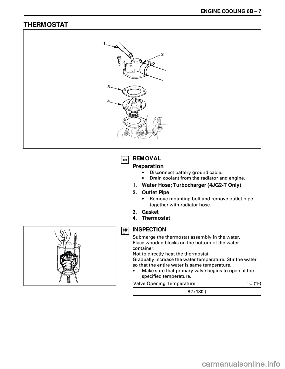
THERMOSTAT
REMOVAL
Preparation
·Disconnect battery ground cable.
·Drain coolant from the radiator and engine.
1. Water Hose; Turbocharger (4JG2-T Only)
2. Outlet Pipe
·Remove mounting bolt and remove outlet pipe
together with radiator hose.
3. Gasket
4. Thermostat
INSPECTION
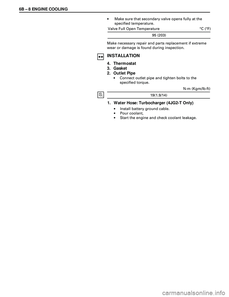
Submerge the thermostat assembly in the water.
Place wooden blocks on the bottom of the water
container.
Not to directly heat the thermostat.
Gradually increase the water temperature. Stir the water
so that the entire water is same temperature.
·Make sure that primary valve begins to open at the
specified temperature.
82 (180 )
°C (°F) Valve Opening Temperature
Page 1662 of 3573
6B Ð 8 ENGINE COOLING
·Make sure that secondary valve opens fully at the
specified temperature.
Make necessary repair and parts replacement if extreme
wear or damage is found during inspection.
INSTALLATION
4. Thermostat
3. Gasket
2. Outlet Pipe
·Connect outlet pipe and tighten bolts to the
specified torque.
19(1.9/14)
N·m (Kgm/lb·ft)
1. Water Hose: Turbocharger (4JG2-T Only)
·Install battery ground cable.
·Pour coolant,
·Start the engine and check coolant leakage.
95 (203)
°C (°F) Valve Full Open Temperature
Page 1670 of 3573
6C Ð 4 FUEL SYSTEM
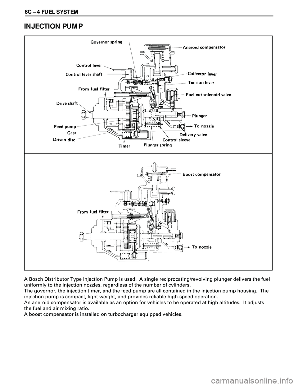
INJECTION PUMP
A Bosch Distributor Type Injection Pump is used. A single reciprocating/revolving plunger delivers the fuel
uniformly to the injection nozzles, regardless of the number of cylinders.
The governor, the injection timer, and the feed pump are all contained in the injection pump housing. The
injection pump is compact, light weight, and provides reliable high-speed operation.
An aneroid compensator is available as an option for vehicles to be operated at high altitudes. It adjusts
the fuel and air mixing ratio.
A boost compensator is installed on turbocharger equipped vehicles.
Page 1734 of 3573
ENGINE MECHANICAL 6A – 1
ENGINE
ENGINE MECHANICAL
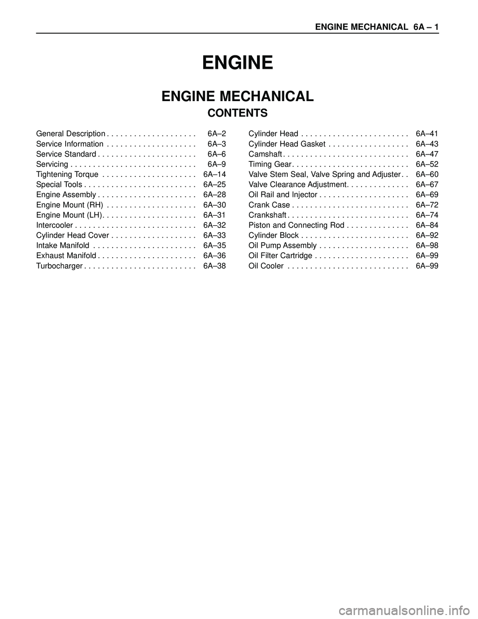
CONTENTS
General Description . . . . . . . . . . . . . . . . . . . . 6A–2
Service Information . . . . . . . . . . . . . . . . . . . . 6A–3
Service Standard . . . . . . . . . . . . . . . . . . . . . . 6A–6
Servicing . . . . . . . . . . . . . . . . . . . . . . . . . . . . 6A–9
Tightening Torque . . . . . . . . . . . . . . . . . . . . . 6A–14
Special Tools . . . . . . . . . . . . . . . . . . . . . . . . . 6A–25
Engine Assembly . . . . . . . . . . . . . . . . . . . . . . 6A–28
Engine Mount (RH) . . . . . . . . . . . . . . . . . . . . 6A–30
Engine Mount (LH). . . . . . . . . . . . . . . . . . . . . 6A–31
Intercooler . . . . . . . . . . . . . . . . . . . . . . . . . . . 6A–32
Cylinder Head Cover . . . . . . . . . . . . . . . . . . . 6A–33
Intake Manifold . . . . . . . . . . . . . . . . . . . . . . . 6A–35
Exhaust Manifold . . . . . . . . . . . . . . . . . . . . . . 6A–36
Turbocharger . . . . . . . . . . . . . . . . . . . . . . . . . 6A–38Cylinder Head . . . . . . . . . . . . . . . . . . . . . . . . 6A–41
Cylinder Head Gasket . . . . . . . . . . . . . . . . . . 6A–43
Camshaft . . . . . . . . . . . . . . . . . . . . . . . . . . . . 6A–47
Timing Gear . . . . . . . . . . . . . . . . . . . . . . . . . . 6A–52
Valve Stem Seal, Valve Spring and Adjuster . . 6A–60
Valve Clearance Adjustment. . . . . . . . . . . . . . 6A–67
Oil Rail and Injector . . . . . . . . . . . . . . . . . . . . 6A–69
Crank Case . . . . . . . . . . . . . . . . . . . . . . . . . . 6A–72
Crankshaft . . . . . . . . . . . . . . . . . . . . . . . . . . . 6A–74
Piston and Connecting Rod . . . . . . . . . . . . . . 6A–84
Cylinder Block . . . . . . . . . . . . . . . . . . . . . . . . 6A–92
Oil Pump Assembly . . . . . . . . . . . . . . . . . . . . 6A–98
Oil Filter Cartridge . . . . . . . . . . . . . . . . . . . . . 6A–99
Oil Cooler . . . . . . . . . . . . . . . . . . . . . . . . . . . 6A–99
Page 1736 of 3573
ENGINE MECHANICAL 6A – 3
SERVICE INFORMATION
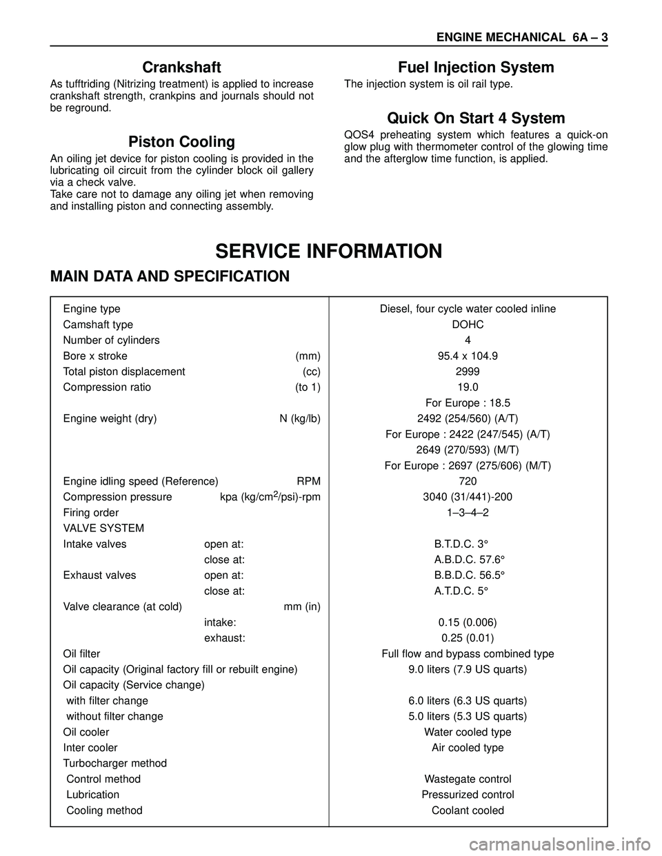
MAIN DATA AND SPECIFICATION
Engine type Diesel, four cycle water cooled inline
Camshaft type DOHC
Number of cylinders 4
Bore x stroke (mm) 95.4 x 104.9
Total piston displacement (cc) 2999
Compression ratio (to 1) 19.0
For Europe : 18.5
Engine weight (dry) N (kg/lb) 2492 (254/560) (A/T)
For Europe : 2422 (247/545) (A/T)
2649 (270/593) (M/T)
For Europe : 2697 (275/606) (M/T)
Engine idling speed (Reference) RPM 720
Compression pressure kpa (kg/cm
2/psi)-rpm 3040 (31/441)-200
Firing order 1–3–4–2
VALVE SYSTEM
Intake valves open at: B.T.D.C. 3°
close at: A.B.D.C. 57.6°
Exhaust valves open at: B.B.D.C. 56.5°
close at: A.T.D.C. 5°
Valve clearance (at cold) mm (in)
intake: 0.15 (0.006)
exhaust: 0.25 (0.01)
Oil filter Full flow and bypass combined type
Oil capacity (Original factory fill or rebuilt engine) 9.0 liters (7.9 US quarts)
Oil capacity (Service change)
with filter change 6.0 liters (6.3 US quarts)
without filter change 5.0 liters (5.3 US quarts)
Oil cooler Water cooled type
Inter cooler Air cooled type
Turbocharger method
Control method Wastegate control
Lubrication Pressurized control
Cooling method Coolant cooled
Crankshaft
As tufftriding (Nitrizing treatment) is applied to increase
crankshaft strength, crankpins and journals should not
be reground.
Piston Cooling
An oiling jet device for piston cooling is provided in the
lubricating oil circuit from the cylinder block oil gallery
via a check valve.
Take care not to damage any oiling jet when removing
and installing piston and connecting assembly.
Fuel Injection System
The injection system is oil rail type.
Quick On Start 4 System
QOS4 preheating system which features a quick-on
glow plug with thermometer control of the glowing time
and the afterglow time function, is applied.
Page 1758 of 3573
901RT034
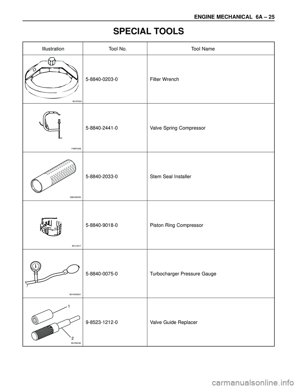
Illustration Tool No. Tool Name
ENGINE MECHANICAL 6A – 25
SPECIAL TOOLS
5-8840-0203-0 Filter Wrench
5-8840-2441-0 Valve Spring Compressor
5-8840-2033-0 Stem Seal Installer
5-8840-9018-0 Piston Ring Compressor
5-8840-0075-0 Turbocharger Pressure Gauge
9-8523-1212-0 Valve Guide Replacer
F06RV038
5884020330
901LX017
901RX00001
1
2
901RW182
Page 1765 of 3573
6A – 32 ENGINE MECHANICAL
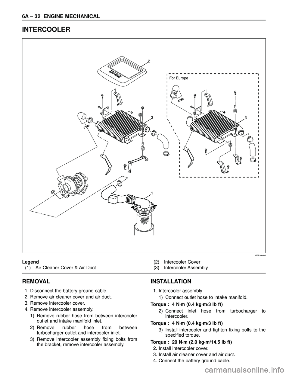
INTERCOOLER
REMOVAL
1. Disconnect the battery ground cable.
2. Remove air cleaner cover and air duct.
3. Remove intercooler cover.
4. Remove intercooler assembly.
1) Remove rubber hose from between intercooler
outlet and intake manifold inlet.
2) Remove rubber hose from between
turbocharger outlet and intercooler inlet.
3) Remove intercooler assembly fixing bolts from
the bracket, remove intercooler assembly.
INSTALLATION
1. Intercooler assembly
1) Connect outlet hose to intake manifold.
Torque : 4 N·m (0.4 kg·m/3 lb ft)
2) Connect inlet hose from turbocharger to
intercooler.
Torque : 4 N·m (0.4 kg·m/3 lb ft)
3) Install intercooler and tighten fixing bolts to the
specified torque.
Torque : 20 N·m (2.0 kg·m/14.5 lb ft)
2. Install intercooler cover.
3. Install air cleaner cover and air duct.
4. Connect the battery ground cable.
For Europe
2
33
1
135R200003
Legend
(1) Air Cleaner Cover & Air Duct(2) Intercooler Cover
(3) Intercooler Assembly
Page 1769 of 3573
6A – 36 ENGINE MECHANICAL
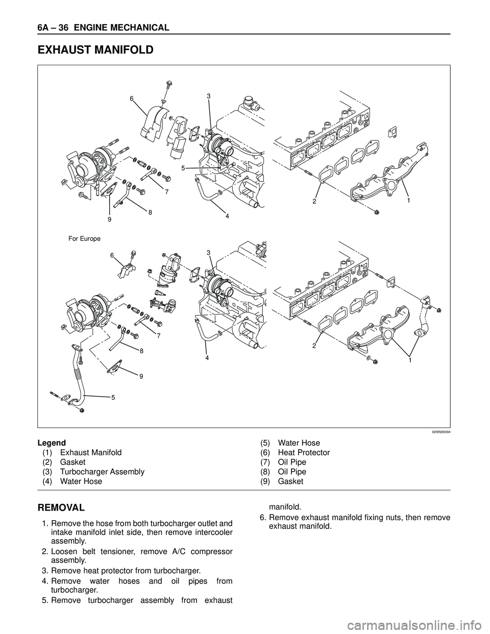
EXHAUST MANIFOLD
9
598 For Europe875 63
21
4
7
4
2
1
36
025R200004
Legend
(1) Exhaust Manifold
(2) Gasket
(3) Turbocharger Assembly
(4) Water Hose(5) Water Hose
(6) Heat Protector
(7) Oil Pipe
(8) Oil Pipe
(9) Gasket
REMOVAL
1. Remove the hose from both turbocharger outlet and
intake manifold inlet side, then remove intercooler
assembly.
2. Loosen belt tensioner, remove A/C compressor
assembly.
3. Remove heat protector from turbocharger.
4. Remove water hoses and oil pipes from
turbocharger.
5. Remove turbocharger assembly from exhaustmanifold.
6. Remove exhaust manifold fixing nuts, then remove
exhaust manifold.