Page 2146 of 3573
INDUCTION 6J – 5
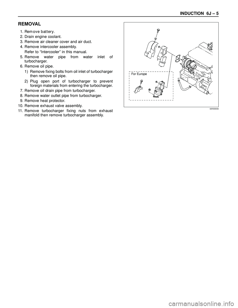
REMOVAL
1. Remove battery.
2. Drain engine coolant.
3. Remove air cleaner cover and air duct.
4. Remove intercooler assembly.
Refer to “Intercooler” in this manual.
5. Remove water pipe from water inlet of
turbocharger.
6. Remove oil pipe.
1) Remove fixing bolts from oil inlet of turbocharger
then remove oil pipe.
2) Plug open port of turbocharger to prevent
foreign materials from entering the turbocharger.
7. Remove oil drain pipe from turbocharger.
8. Remove water outlet pipe from turbocharger.
9. Remove heat protector.
10. Remove exhaust valve assembly.
11. Remove turbocharger fixing nuts from exhaust
manifold then remove turbocharger assembly.
For Europe
025R200006
Page 2148 of 3573
INDUCTION 6J – 7
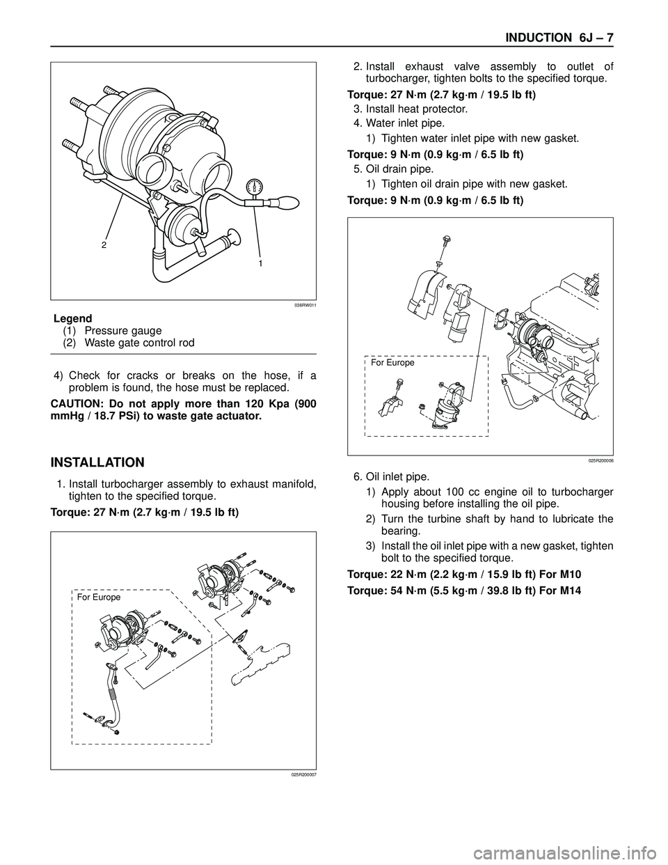
Legend
(1) Pressure gauge
(2) Waste gate control rod
4) Check for cracks or breaks on the hose, if a
problem is found, the hose must be replaced.
CAUTION: Do not apply more than 120 Kpa (900
mmHg / 18.7 PSi) to waste gate actuator.
INSTALLATION
1. Install turbocharger assembly to exhaust manifold,
tighten to the specified torque.
Torque: 27 N·m (2.7 kg·m / 19.5 lb ft)2. Install exhaust valve assembly to outlet of
turbocharger, tighten bolts to the specified torque.
Torque: 27 N·m (2.7 kg·m / 19.5 lb ft)
3. Install heat protector.
4. Water inlet pipe.
1) Tighten water inlet pipe with new gasket.
Torque: 9 N·m (0.9 kg·m / 6.5 lb ft)
5. Oil drain pipe.
1) Tighten oil drain pipe with new gasket.
Torque: 9 N·m (0.9 kg·m / 6.5 lb ft)
6. Oil inlet pipe.
1) Apply about 100 cc engine oil to turbocharger
housing before installing the oil pipe.
2) Turn the turbine shaft by hand to lubricate the
bearing.
3) Install the oil inlet pipe with a new gasket, tighten
bolt to the specified torque.
Torque: 22 N·m (2.2 kg·m / 15.9 lb ft) For M10
Torque: 54 N·m (5.5 kg·m / 39.8 lb ft) For M14
2
1
036RW011
For Europe
025R200007
For Europe
025R200006
Page 2150 of 3573
INDUCTION 6J – 9
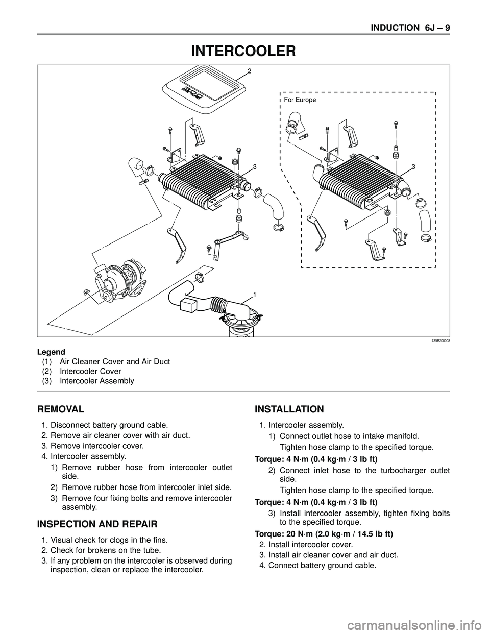
INTERCOOLER
REMOVAL
1. Disconnect battery ground cable.
2. Remove air cleaner cover with air duct.
3. Remove intercooler cover.
4. Intercooler assembly.
1) Remove rubber hose from intercooler outlet
side.
2) Remove rubber hose from intercooler inlet side.
3) Remove four fixing bolts and remove intercooler
assembly.
INSPECTION AND REPAIR
1. Visual check for clogs in the fins.
2. Check for brokens on the tube.
3. If any problem on the intercooler is observed during
inspection, clean or replace the intercooler.
INSTALLATION
1. Intercooler assembly.
1) Connect outlet hose to intake manifold.
Tighten hose clamp to the specified torque.
Torque: 4 N·m (0.4 kg·m / 3 lb ft)
2) Connect inlet hose to the turbocharger outlet
side.
Tighten hose clamp to the specified torque.
Torque: 4 N·m (0.4 kg·m / 3 lb ft)
3) Install intercooler assembly, tighten fixing bolts
to the specified torque.
Torque: 20 N·m (2.0 kg·m / 14.5 lb ft)
2. Install intercooler cover.
3. Install air cleaner cover and air duct.
4. Connect battery ground cable.
For Europe
2
33
1
Legend
(1) Air Cleaner Cover and Air Duct
(2) Intercooler Cover
(3) Intercooler Assembly
135R200003
Page 2153 of 3573
6J – 12 INDUCTION
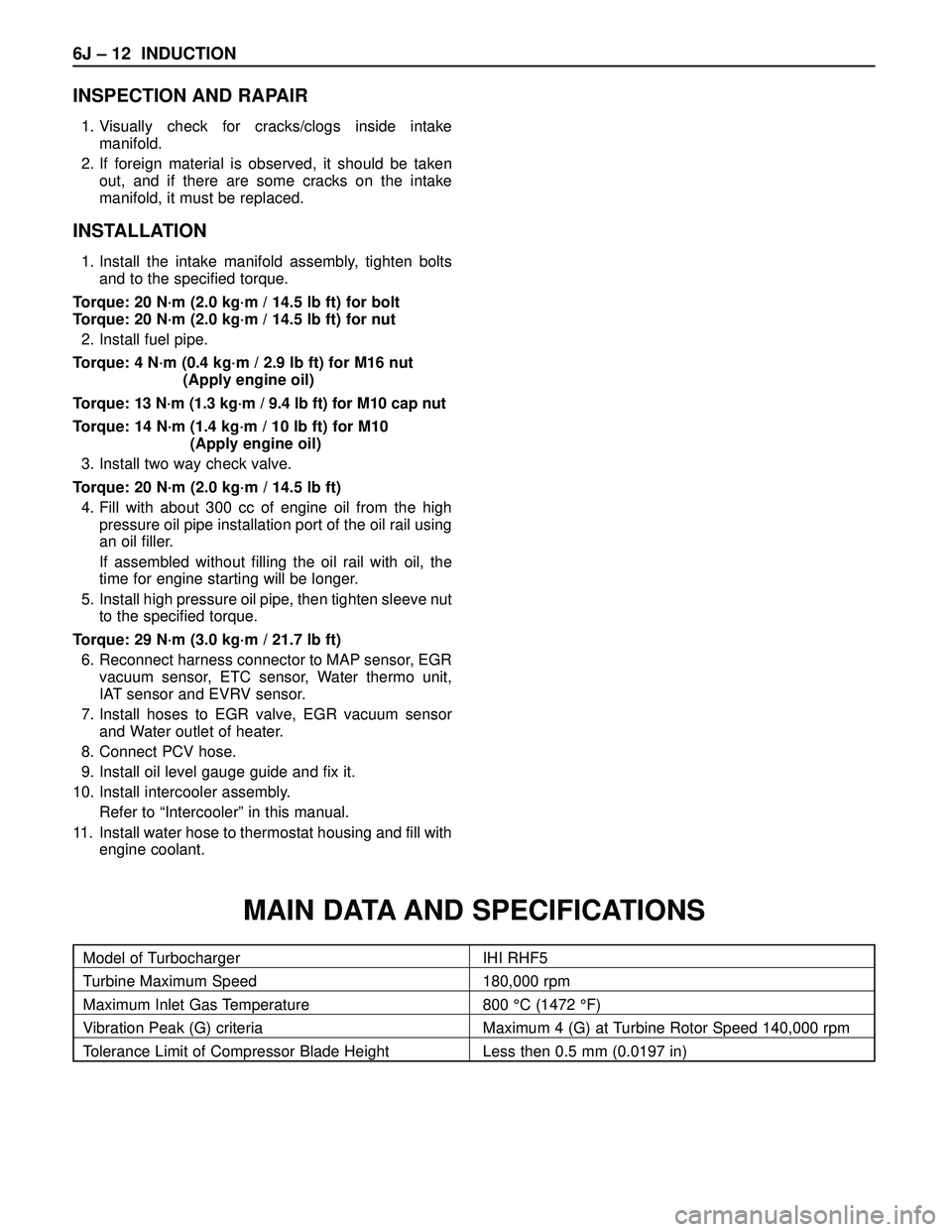
INSPECTION AND RAPAIR
1. Visually check for cracks/clogs inside intake
manifold.
2. If foreign material is observed, it should be taken
out, and if there are some cracks on the intake
manifold, it must be replaced.
INSTALLATION
1. Install the intake manifold assembly, tighten bolts
and to the specified torque.
Torque: 20 N·m (2.0 kg·m / 14.5 lb ft) for bolt
Torque: 20 N·m (2.0 kg·m / 14.5 lb ft) for nut
2. Install fuel pipe.
Torque: 4 N·m (0.4 kg·m / 2.9 lb ft) for M16 nut
(Apply engine oil)
Torque: 13 N·m (1.3 kg·m / 9.4 lb ft) for M10 cap nut
Torque: 14 N·m (1.4 kg·m / 10 lb ft) for M10
(Apply engine oil)
3. Install two way check valve.
Torque: 20 N·m (2.0 kg·m / 14.5 lb ft)
4. Fill with about 300 cc of engine oil from the high
pressure oil pipe installation port of the oil rail using
an oil filler.
If assembled without filling the oil rail with oil, the
time for engine starting will be longer.
5. Install high pressure oil pipe, then tighten sleeve nut
to the specified torque.
Torque: 29 N·m (3.0 kg·m / 21.7 lb ft)
6. Reconnect harness connector to MAP sensor, EGR
vacuum sensor, ETC sensor, Water thermo unit,
IAT sensor and EVRV sensor.
7. Install hoses to EGR valve, EGR vacuum sensor
and Water outlet of heater.
8. Connect PCV hose.
9. Install oil level gauge guide and fix it.
10. Install intercooler assembly.
Refer to “Intercooler” in this manual.
11. Install water hose to thermostat housing and fill with
engine coolant.
Model of Turbocharger IHI RHF5
Turbine Maximum Speed 180,000 rpm
Maximum Inlet Gas Temperature 800 °C (1472 °F)
Vibration Peak (G) criteria Maximum 4 (G) at Turbine Rotor Speed 140,000 rpm
Tolerance Limit of Compressor Blade Height Less then 0.5 mm (0.0197 in)
MAIN DATA AND SPECIFICATIONS
Page 2154 of 3573
INDUCTION 6J – 13
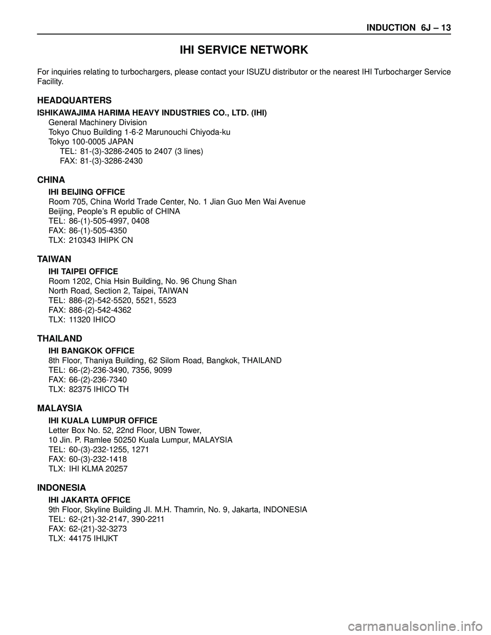
IHI SERVICE NETWORK
For inquiries relating to turbochargers, please contact your ISUZU distributor or the nearest IHI Turbocharger Service
Facility.
HEADQUARTERS
ISHIKAWAJIMA HARIMA HEAVY INDUSTRIES CO., LTD. (IHI)
General Machinery Division
Tokyo Chuo Building 1-6-2 Marunouchi Chiyoda-ku
Tokyo 100-0005 JAPAN
TEL: 81-(3)-3286-2405 to 2407 (3 lines)
FAX: 81-(3)-3286-2430
CHINA
IHI BEIJING OFFICE
Room 705, China World Trade Center, No. 1 Jian Guo Men Wai Avenue
Beijing, People’s R epublic of CHINA
TEL: 86-(1)-505-4997, 0408
FAX: 86-(1)-505-4350
TLX: 210343 IHIPK CN
TA I WA N
IHI TAIPEI OFFICE
Room 1202, Chia Hsin Building, No. 96 Chung Shan
North Road, Section 2, Taipei, TAIWAN
TEL: 886-(2)-542-5520, 5521, 5523
FAX: 886-(2)-542-4362
TLX: 11320 IHICO
THAILAND
IHI BANGKOK OFFICE
8th Floor, Thaniya Building, 62 Silom Road, Bangkok, THAILAND
TEL: 66-(2)-236-3490, 7356, 9099
FAX: 66-(2)-236-7340
TLX: 82375 IHICO TH
MALAYSIA
IHI KUALA LUMPUR OFFICE
Letter Box No. 52, 22nd Floor, UBN Tower,
10 Jin. P. Ramlee 50250 Kuala Lumpur, MALAYSIA
TEL: 60-(3)-232-1255, 1271
FAX: 60-(3)-232-1418
TLX: IHI KLMA 20257
INDONESIA
IHI JAKARTA OFFICE
9th Floor, Skyline Building JI. M.H. Thamrin, No. 9, Jakarta, INDONESIA
TEL: 62-(21)-32-2147, 390-2211
FAX: 62-(21)-32-3273
TLX: 44175 IHIJKT
Page 3567 of 3573
PAGE BACK PAGE NEXT
4JG2
4JX1 SECTION No. CONTRNTS
00 SERVICE INFORMATION
6A ENGINE MECHANICAL
6A2 4JG2-NA / 4JG2-TURBO ENGINE
6B ENGINE COOLING
6C FUEL SYSTEM
6D ENGINE ELECTRICAL
6E -
6F EXHAUST
6G -
SECTION No. CONTRNTS
6A ENGINE MECHANICAL
6B ENGINE COOLING
6C ENGINE FUEL
6D ENGINE ELECTRICAL
6E ENGINE DRIVEABILITY AND EMISSIONS
6F ENGINE EXHAUST
6G ENGINE LUBRICATION
6H ENGINE SPEED CONTROL
6J INDUCTION