8F±16BODY STRUCTURE
5. Remove cowl cover.
�Disconnect three screws.
6. Remove cowl cover seals.
7. Remove front window lower molding.8. Remove cowl cover stoppers.
Installation
To install, follow the removal steps in reverse order.
Engine Hood
Removal
1. Open the hood.
2. Support the hood.
3. Remove windowshield washer nozzle tube.
880RS001
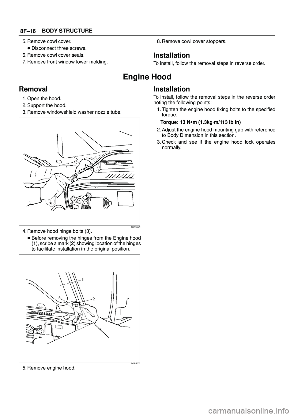
4. Remove hood hinge bolts (3).
�Before removing the hinges from the Engine hood
(1), scribe a mark (2) showing location of the hinges
to facilitate installation in the original position.
610RS003
5. Remove engine hood.
Installation
To install, follow the removal steps in the reverse order
noting the following points:
1. Tighten the engine hood fixing bolts to the specified
torque.
Torque: 13 Nwm (1.3kg´m/113 lb in)
2. Adjust the engine hood mounting gap with reference
to Body Dimension in this section.
3. Check and see if the engine hood lock operates
normally.
8H±22SECURITY AND LOCKS
Anti-theft System
General Description
The circuit consists of the starter switch, anti-theft &
keyless entry control unit, anti-theft horn, front door and
tailgate key switch (detect and tamper switch), door lock
(& power window) switch, door lock actuator for each
door, engine hood switch, clutch start switch (M/T),
ANTI-THEFT indicator light and mode switch (A/T).
The system operates as follows: After locking the starter
switch and removing the starter key (this sets the alarm),
if the door is unlocked in any way other than with the
proper key, the headlights start flashing, the horn sounds,
and the starter circuit is disabled. (However, the engine
hood and all the doors must be locked and closed.)
Once the system has been placed in the warning or alarm
condition, it can be released only when the starter switch
is shifted from ªOFFº to ªACCº by the starter key, or when
the lock of the front door or the tailgate is released (to
activate the detect switch) by the starter key.
Anti-theft & Keyless Entry Control
Unit Removal
1. Disconnect the battery ground cable.
2. Remove the front console assembly.
�Refer to the Instrument Panel Assembly in Body
Structure section.
3. Remove the lower cluster assembly.
�Refer to the Instrument Panel Assembly in Body
Structure section.
4. Disconnect the connector(2).
5. Remove four screws to remove the anti-theft &
keyless entry control unit with bracket(1).
825RW029
6. Remove two nuts from the anti-theft & keyless entry
control unit with bracket(3) to remove the anti-theft &
keyless entry controller(4).
825RW028
Anti-theft & Keyless Entry Control
Unit Installation
To install, follow the removal steps in the reverse order.
Anti-theft Indicator Removal
1. Disconnect the battery ground cable.
2. Remove the front console assembly(1).
Refer to the Instrument Panel Assembly in Body
Structure section.
3. Remove the lower cluster assembly(2).
Refer to the Instrument Panel Assembly in Body
Structure section.
4. Remove the instrument panel driver lower cover
assembly(3).
Refer to the Instrument Panel Assembly in Body
Structure section.
821RW024
SUPPLEMENTAL RESTRAINT SYSTEM 9J±40
3. Disconnect the yellow 2±pin connector located
behind the air bag assembly and remove air bag
assembly.Refer to ªSRS Connectorsº in this section
for removal and installation.
4. Disconnect horn lead connector.
827RT009
5. Remove the steering wheel attachment nut.
6. Apply a setting mark across the steering wheel and
shaft so parts can be reassembled in their original
position.
430RS004
7. Move the tires to the straight ahead position before
removing the steering wheel and remove wheel with
5±8521±0016±0.
430RT009
8. Feed wiring though the wheel and remove wheel.
9. Remove the steering lower cover and engine hood
opening lever.
10. Remove the driver knee bolster assembly.
11. Remove the steering column cover.
12. Remove air conditioning lower duct.
13. Disconnect the 12±pin wiring harness connectors
located at the base of steering column.
CAUTION: Never apply force to the steering wheel
in the direction of the shaft by using a hammer or
other impact tools in an attempt to remove the
steering wheel. The steering shaft is designed as an
energy absorbing unit.
14. Remove the combination switch assembly with SRS
coil.
SUPPLEMENTAL RESTRAINT SYSTEM9J±45
3. Disconnect the yellow 2±pin connector located
behind the air bag assembly and remove air bag
assembly.Refer to ªSRS Connectorsº in this section
for removal and installation.
827RT009
4. Disconnect horn lead connector.
5. Remove the steering wheel attachment nut.
6. Apply a setting mark across the steering wheel and
shaft so parts can be reassembled in their original
position.
430RS004
7. Move the tires to the straight ahead position before
removing the steering wheel and removing wheel with
5±8521±0016±0.
430RT009
8. Feed wiring though the wheel and remove wheel.
9. Remove the steering lower cover and engine hood
opening lever.
10. Remove the driver knee bolster assembly.
740RT015
11. Remove the steering column cover.
12. Remove air conditioning lower duct.
13. Disconnect the wiring harness connectors located at
the base of steering column.
CAUTION: Never apply force to the steering wheel
in direction of the shaft by using a hammer or other
impact tools in an attempt to remove the steering
wheel. The steering shaft is designed as an energy
absorbing unit.
14. Remove the combination switch assembly with SRS
coil.