Page 2019 of 3573
6E±126
4JX1±TC ENGINE DRIVEABILITY AND EMISSIONS
Diagnostic Trouble Code (DTC) P0380 (Flash DTC 66)
Glow Relay Circuit Open/Short
060RW132
Circuit Description
Glow relay circuit receives current through Glow 50A fuse
from the battery. Glow relay is circuited to Glow plug.
Action Taken When the DTC Sets
�The ECM will store conditions which were present
when the DTC was set as Freeze Frame and in the
Failure Records data.
Conditions for Clearing the MIL/DTC
�DTC P0380 can be cleared by using the Tech 2 ªClear
Infoº function or by disconnecting the ECM battery
feed.
Diagnostic Aids
An intermittent may be caused by a poor connection,
rubbed-through wire insulation or a wire broken inside the
insulation. Check for:
�Poor connection ± Inspect the ECM harness and
connectors for improper mating, broken locks,
improperly formed or damaged terminals, and poor
terminal-to-wire connection.
�Damaged harness ± Inspect the wiring harness for
damage.
Page 2020 of 3573
Ye sNo
1Was the ªOn-Board Diagnostic (OBD) System Checkº
performed?
ÐGo to Step 2
Go")
6E±127 4JX1±TC ENGINE DRIVEABILITY AND EMISSIONS
DTC P0380 ± Glow Relay Circuit Open/Short�
StepActionValue(s)Ye sNo
1Was the ªOn-Board Diagnostic (OBD) System Checkº
performed?
ÐGo to Step 2
Go to OBD
System
Check
2Attempt to start the engine.
Does the engine start?
ÐGo to Step 3Go to Chart 3
31. Review and record Failure Records information.
2. Clear DTC P0380.
3. Start the engine and idle for 1 minute.
4. Observe DTCs.
Is DTC P0380 set?
ÐGo to Step 4
Refer to
Diagnostic
Aid
4Check the glow fuse 50A.
Is the glow fuse 50A damage?
ÐGo to Step 5Go to Step 6
5Replace the glow fuse 50A.
Is the action complete?
ÐVerify repairGo to Step 6
61. Ignition ªOFF.º
2. Check for an open or a short to ground in the Glow
relay circuit between the Glow relay connector and
the ECM harness connector.
3. If a problem is found, repair as necessary.
Was a problem found?
ÐVerify repairGo to Step 7
7Check the connections at the Glow relay and replace
the terminals if necessary.
Did any terminals require replacement?
ÐVerify repairGo to Step 8
8Replace the Glow relay.
Is the action complete?
ÐVerify repairGo to Step 9
9Check the connections at the ECM and replace the
terminals if necessary.
Did any terminals require replacement?
ÐVerify repair Go to Step 10
10Replace the ECM (Refer to the Data Programming in
Case of ECM change).
Is the action complete?
ÐVerify repairÐ
Page 2021 of 3573
6E±128
4JX1±TC ENGINE DRIVEABILITY AND EMISSIONS
Diagnostic Trouble Code (DTC) P0381 (Flash DTC 67)
Glow Lamp Circuit Open/Short
060RW136
Circuit Description
Glow Lamp Circuit receives current through Meter 10A
fuse, Glow lamp being circuited to ECM.
Action Taken When the DTC Sets
�The ECM will store conditions which were present
when the DTC was set as Freeze Frame and in the
Failure Records data.
Conditions for Clearing the MIL/DTC
�DTC P0381 can be cleared by using the Tech 2 ªClear
Infoº function or by disconnecting the ECM battery
feed.
Diagnostic Aids
An intermittent may be caused by a poor connection,
rubbed-through wire insulation or a wire broken inside the
insulation. Check for:
�Poor connection ± Inspect the ECM harness and
connectors for improper mating, broken locks,
improperly formed or damaged terminals, and poor
terminal-to-wire connection.
�Damaged harness ± Inspect the wiring harness for
damage.
Page 2022 of 3573
6E±129 4JX1±TC ENGINE DRIVEABILITY AND EMISSIONS
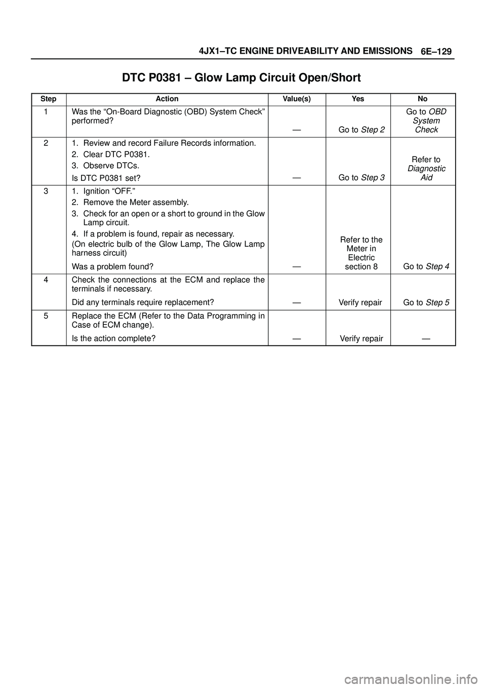
DTC P0381 ± Glow Lamp Circuit Open/Short�
StepActionValue(s)Ye sNo
1Was the ªOn-Board Diagnostic (OBD) System Checkº
performed?
ÐGo to Step 2
Go to OBD
System
Check
21. Review and record Failure Records information.
2. Clear DTC P0381.
3. Observe DTCs.
Is DTC P0381 set?
ÐGo to Step 3
Refer to
Diagnostic
Aid
31. Ignition ªOFF.º
2. Remove the Meter assembly.
3. Check for an open or a short to ground in the Glow
Lamp circuit.
4. If a problem is found, repair as necessary.
(On electric bulb of the Glow Lamp, The Glow Lamp
harness circuit)
Was a problem found?
Ð
Refer to the
Meter in
Electric
section 8
Go to Step 4
4Check the connections at the ECM and replace the
terminals if necessary.
Did any terminals require replacement?
ÐVerify repair Go to Step 5
5Replace the ECM (Refer to the Data Programming in
Case of ECM change).
Is the action complete?
ÐVerify repairÐ
Page 2023 of 3573
 P1403 (Flash DTC 32)
EGR EVRV Fault
060RW135
Circuit Description
EGR EVRV Circuit has a common power source in
paralle")
6E±130
4JX1±TC ENGINE DRIVEABILITY AND EMISSIONS
Diagnostic Trouble Code (DTC) P1403 (Flash DTC 32)
EGR EVRV Fault
060RW135
Circuit Description
EGR EVRV Circuit has a common power source in
parallel with EGR, VSV, RPCV, and Intake Throttle Motor.
This may cause multiple DTCs. On such occasion, refer
to ªMultiple ECM Information sensor DTCs Setº.
Diagnostic Aids
Check for the following conditions:
�Poor connection or damaged EVRV ± Inspect the
wiring harness for damage.
�Ensure EVRV is correctly mounted. See
On-Vehicle
Service.
Reviewing the Failure Records vehicle mileage since the
diagnostic test last failed may help determine how often
the condition that caused the DTC to be set occurs. This
may assist in diagnosing the condition.
Test Description
Number(s) below refer to the step number(s) on the
Diagnostic Chart
3. A malfunctioning MAP sensor can set an EGR DTC.
The MAP sensor could send a constant signal which
is not low enough to set a low MAP DTC. The
constant signal from the MAP sensor also may not
be high enough to set a high MAP DTC. This step
verifies that the MAP sensor is responding.
Page 2024 of 3573
Ye sNo
1Was the ªOn-Board Diagnostic (OBD) System Checkº
performed?
ÐGo to Step 2
Go to OBD
System")
6E±131 4JX1±TC ENGINE DRIVEABILITY AND EMISSIONS
DTC P1403 ± EGR EVRV Fault�
StepActionValue(s)Ye sNo
1Was the ªOn-Board Diagnostic (OBD) System Checkº
performed?
ÐGo to Step 2
Go to OBD
System
Check
2Check the EVRV circuit.
Was the EVRV circuit darmage?
Ð
Replace the
EVRV circuit
Go to Step 3
31. Start the engine.
2. Monitor the MAP signal with a scan tool while idling.
3. While idling, jab the accelerator pedal about halfway
down and immediately let the engine return to idle.
Did the MAP value on the scan tool show an immediate
large change?
ÐGo to Step 5Go to Step 4
4Replace the MAP sensor.
Is the action complete?
ÐVerify repairÐ
51. Inspect the exhaust system for modification of
original installed parts or leaks.
2. If a problem was found, repair exhaust system as
necessary.
Was a condition present that required repair?
ÐGo to Step 8Go to Step 6
61. Remove the EGR valve.
2. Visually and physically inspect the pintle, valve
passages and the adapter for excessive deposits or
any kind of a restriction.
3. If a problem is found, clean or replace EGR system
components as necessary.
Was a condition present that required repair?
ÐGo to Step 8Go to Step 7
71. Inspect the EGR passages for a blockage caused
by excessive deposits or other damage.
2. If a problem is found, correct the condition as
necessary.
Was a condition present that required repair?
ÐGo to Step 8
Refer to
Diagnostic
Aids
81. Review and record the scan tool Failure Records
data.
2. Clear DTC and monitor the scan tool System Info
Screen while operating the vehicle as specified in
ªDiagnostic Aids.º
3. Using a scan tool, monitor ªDTCº info for DTC
P1403 until the DTC P1403 test runs.
4. Note the test result.
Does the scan tool indicate DTC P1403 failed this
ignition?
Ð
Go to the last
step
completed in
this
diagnostic
chart
Repair
complete
Page 2025 of 3573
 P1404 (Flash DTC 31)
EGR VSV Circuit
060RW135
Circuit Description
The Engine control module (ECM) monitors the EGR
val")
6E±132
4JX1±TC ENGINE DRIVEABILITY AND EMISSIONS
Diagnostic Trouble Code (DTC) P1404 (Flash DTC 31)
EGR VSV Circuit
060RW135
Circuit Description
The Engine control module (ECM) monitors the EGR
valve input to ensure that the valve responds properly to
commands from the ECM, and to detect a fault if VSV is
stuck open. When the VSV is fixing at closed and opening
the ECM will set DTC P1404.
Diagnostic Aids
Check for the following conditions:
�Poor connection or damaged VSV±inspect the wiring
harness for damage.
DTC P1404 ± EGR VSV Circuit�
StepActionValue(s)Ye sNo
1Was the ªOn-Board Diagnostic (OBD) System Checkº
performed?
ÐGo to Step 2
Go to OBD
System
Check
21. Ignition ªONº, engine ªOFFº, review and record
scan tool Failure Records data.
2. Operate the vehicle within Failure Records
conditions as noted.
3. Using a scan tool, monitor ªSpecific DTCº info for
DTC P1404 until the DTC P1404 test runs. Note the
result.
Does the scan tool indicates DTC P1404 failed this
ignition?
ÐGo to Step 3
Refer to
Diagnostic
Aids
Page 2026 of 3573
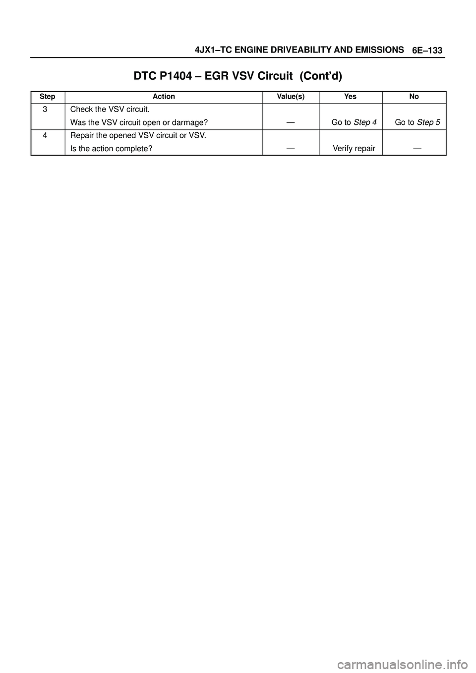
6E±133 4JX1±TC ENGINE DRIVEABILITY AND EMISSIONS
DTC P1404 ± EGR VSV Circuit������ ���
StepNo Ye s Value(s) Action
3Check the VSV circuit.
Was the VSV circuit open or darmage?
ÐGo to Step 4Go to Step 5
4Repair the opened VSV circuit or VSV.
Is the action complete?
ÐVerify repairÐ
 P0380 (Flash DTC 66)
Glow Relay Circuit Open/Short
060RW132
Circuit Description
Glow relay circuit receives current th")
 P0381 (Flash DTC 67)
Glow Lamp Circuit Open/Short
060RW136
Circuit Description
Glow Lamp Circuit receives current thro")