Page 2872 of 3573

WIRING SYSTEM 8DÐ279
Diagnosis
The cruise control unit uses the cruise main indicator light and diagnoses the failure, when the control unit
detects abnormality on the table below.
PART POSIBLE CAUSE DETECTION PERIOD DTC
Motor system short circuit Energizing motor 1Ð1
Clutch system short circuit Energizing clutch 1Ð2
Actuator Clutch system open circuit Energizing clutch 1Ð2
Mechanical defect Cruise controlling 1Ð3
Close side of motor system open circuit Cruise controlling 1Ð1
CruiseOpen side of motor system continuously energizing While starter sw on 1Ð4
control unit
Clutch output abnormality While starter sw on 1Ð4
VehicleSignal of vehicle speed disconnection Cruise controlling 2Ð1
speed sensor
Signal of vehicle speed abnormality Cruise controlling 2Ð1
SwitchTurning on switch at all times While starter sw on 3Ð1
Turning on switch at the same time. While starter sw on 3Ð1
DTC: Diagnostic Trouble Code
DTC Display Condition
1. While starter switch on and vehicle speed is 0 km/h, the DTC output begins in top priority by cancel switch
turn on and off being repeated three times for 2 sec. while cruise main switch pushing on, and stops the
DTC output whether vehicle speed is more than 10 km/h or the resume switch is turned on.
2. The cruise control unit outputs the DTC(s) in order from small figure of the code.
3. The header of display of DTC(s) is assumed 4 sec., and it is 2 sec. between different kind of codes.
4. The DTC(s) are erased with the starter switch turned off.
DTC Display Format
1. When no DTCs are detected. (The unit : sec.)
2. When two or more DTCs are detected. (The unit ; sec.)
0.25 0.25
Code 1–1 Code 2–2 410.5
11 1 1 1 1 12
Page 2877 of 3573
8DÐ284 WIRING SYSTEM
Anti-lock Brake System (ABS)
General Description
The circuit consists of EHCU (Electronic Hydraulic
Control Unit), wheel speed sensor, GÐsensor,
stoplight switch or brake switch (w/cruise control),
backup light switch, transmission switchÐ1, 2,
indicator light and data link connector.
EHCU controls brake fluid pressure applied to front
and rear wheels to prevent wheels from locking by
using speed sensor and GÐsensor signals.
Based on wheel speed signals from speed sensor,
EHCU activates solenoid valves incorporated into
the control unit to increase, maintain or decrease
brake fluid pressure.
Refer to AntiÐlock Brake System in Brakes section.
Page 2878 of 3573
WIRING SYSTEM 8DÐ285
Circuit Diagram (RHD)-1
2.0
Y/G2.0
W/G 3.0
W/G
0.5
LG FL-6 40A
ABS
F-9 20A
ABS
INDICATOR
LIGHT(METER)
BRAKE
SW STOP
LIGHT
SW
ELECTRONIC
HYDRAULIC
CONTROL UNIT4WD CONTROL
UNIT(19)
14
C-413
C-4
3.0
B/Y3.0
B/Y
0.85
L/W0.5
L/W0.5
L/W
2.0
BC-4 10A
ELEC.IGN.STARTER SW
(IG1)STARTER SW
(IG1)
C-10 10A
METER,GAUGE
I-9
I-10156I-9
2H-26H-1619
H-2718 16
5.0
W
0.85
G/W C-14 15A
STOP,A/T CONT. BATT.(+) BATT.(+)
STOP LIGHT
10
C-430.85
G/W (W/CRUISE CONTROL) 0.85
G/W
0.85
G/Y
0.85
G/Y 0.85
G/Y
0.85
G/Y
B-131B-13
4
B-14H-131B-14
2
G-
SENSOR26
C-4 0.5
L/W
0.5
Y/B
0.5
Y/BB-252B-25
1H-151
8
C-4
6C-39
FENDER-RHH-131C-4
15
16
C-4 0.5
L/Y
0.5
L/Y
0.5
Y
0.5
Y
A
2.0
B(DIESEL)
5C-39
FENDER-RHC-4
15
2.0
BC-85
ENG.ROOM-FRTC-4 GROUND GROUND GROUND BATTERY BATTERY G-SENSOR POWER
SUPPLYSILA BRAKE LIGHT
SWITCH
12
4WDABS
D08RW601
Page 2885 of 3573
8DÐ292 WIRING SYSTEM
Circuit Diagram (LHD)-1
2.0
Y/G2.0
W/G 3.0
W/G
0.5
LG FL-6 40A
ABS
F-9 20A
ABS
INDICATOR
LIGHT(METER)
BRAKE
SWITCH STOP
LIGHT
SWITCH
ELECTRONIC
HYDRAULIC
CONTROL
UNIT4WD CONTROL
UNIT(19)
14
C-413
C-4
3.0
B/Y3.0
B/Y
0.85
L/W0.5
L/W0.5
L/W
2.0
BC-4 10A
ELEC.IGN.STARTER SW
(IG1)STARTER SW
(IG1)
C-10 10A
METER,GAUGE
I-9
I-1015 10I-9
18H-25H-1622
H-2518 16
5.0
W
0.85
G/W C-14 15A
STOP,A/T CONT. BATT.(+) BATT.(+)
STOP LIGHT
10
C-420.85
G/W (W/CRUISE CONTROL) 0.85
G/W
0.85
G/Y
0.85
G/Y 0.85
G/Y
0.85
G/Y
B-131B-13
4
B-14H-131B-14
2
G-
SENSOR26
C-4 0.5
L/W
0.5
Y/B
0.5
Y/BB-252B-25
1H-154
8
C-4
6C-39
FENDER-RHH-125C-4
15
16
C-4 0.5
L/Y
0.5
L/Y
0.5
Y
0.5
Y
A
2.0
BC-85
ENG. ROOM-FRTC-4 GROUND GROUND BATTERY BATTERY G-SENSOR POWER
SUPPLYSILA BRAKE LIGHT
SWITCH
12
4WDABS
2.0
B
5C-39
FENDER-RHC-4
15GROUND
(4JG2)
D08RW793
Page 2892 of 3573
WIRING SYSTEM 8DÐ299
Circuit Diagram (RHD)
0.5
L/W3.0
B/Y
0.85
L/WC-4 10A
ELEC. IGN.STARTER SW
(IG1)BATT.(+)
STOPLIGHT
SHIFT LOCK
SOLENOIDPARKING POSITION
DETECTING SW 1
B-32
0.85
G/W
0.85
G/W
0.85
G/Y
0.85
G/Y0.85
G/W
0.85
G/Y
42
B-32
B-32
B-32
6
0.5
B
2.0
B BODY-LHB-2
2.0
B
BODY-CTRB-26
2.0
B
BODY-RHB-18 AC GENERATOR
(L)5.0
W
C-14 15A
STOP, A/T CONT
5
B-3213H-15
0.85
W/G
STOPLIGHT
SW1
B-14
7H-32B-14
24 1
(W/O CRUISE
CONTROL)BRAKE
SW
B-13B-13
(W/ CRUISE
CONTROL)
SHIFT LOCK CONTROLLER
D08RW659
Page 2894 of 3573
WIRING SYSTEM 8DÐ301
Circuit Diagram (LHD)
0.5
L/W3.0
B/Y
0.5
L/WC-4 10A
ELEC. IGN.STARTER SW
(IG1)BATT.(+)
STOPLIGHT
SHIFT LOCK
SOLENOIDPARKING POSITION
DETECTING SW 1
B-32
0.85
G/W
0.85
G/W
0.85
G/Y
0.85
G/Y0.85
G/W
0.85
G/Y
42
B-32
B-32
B-32
6
0.5
B
2.0
B
BODY-CTR
B-26
AC GENERATOR
(L)5.0
W
C-14 15A
STOP, A/T CONT
5
B-3211H-15
0.85
W/G
STOPLIGHT
SW1
B-14
7H-32B-14
24 1
(W/O CRUISE
CONTROL)BRAKE
SW
B-13B-13
(W/ CRUISE
CONTROL)
SHIFT LOCK CONTROLLER
D08RW956
Page 3004 of 3573
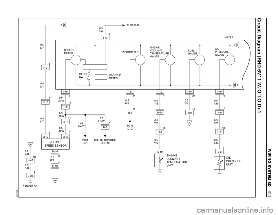
WIRING SYSTEM 8D – 411
Circuit Diagram (RHD 6V*1 W/O T.O.D)-1
�%�����3�8������
3
C-3910H-42
0.5
B/R0.5
B/R 0.5
B/R
B
DC
A
FENDER-RH
H-104M-10
2A
I 0.5
L/Y0.5
L/Y0.5
L/Y
1
M-109H-103H-9
0.5
LG/W0.5
LG/W
0.5
LG/W0.5
LG/W 0.5
LG/W0.5
R/W
SPEEDO-
METER
RESET
SWTACHOMETERENGINE
COOLANT
TEMPERATURE
GAUGEFUEL
GAUGEOIL
PRESSURE
GAUGE FUSE C-15
3
M-10125H-9
11H-10
VEHICLE
SPEED SENSOR
I-10
0.5
Y/B0.5
Y/B0.5
Y/B
1
E-191 4H-24
11H-6I-10
2
H-8
PCM
(D7)CRUISE CONTROL
UNIT(9)0.5
B/R
15
H-9
PCM
(C10)9I-9
0.5
Y/R
14H-2520I-10
ENGINE
COOLANT
TEMPERATURE
UNIT
0.5
Y/G0.5
Y/V0.5
Y/B
1E-217 19H-9
10H-6I-10
OIL
PRESSURE
UNIT
8
I-10METER
ODO/TRIP
METER
Page 3006 of 3573
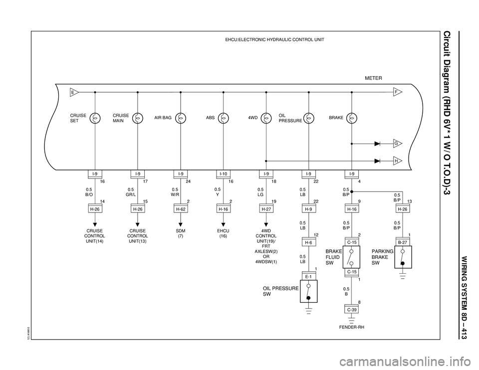
WIRING SYSTEM 8D – 413
�%�����3�8������
Circuit Diagram (RHD 6V*1 W/O T.O.D)-3
GHF
E
16
14 CRUISE
SETCRUISE
MAINAIR BAG ABS 4WD BRAKEEHCU:ELECTRONIC HYDRAULIC CONTROL UNIT
OIL
PRESSURE
CRUISE
CONTROL
UNIT(14)0.5
B/OI-9
H-2617
15
CRUISE
CONTROL
UNIT(13) 0.5
GR/LI-9
H-2624
2
SDM
(7) 0.5
W/RI-9
H-6216
2
EHCU
(16)
OIL PRESSURE
SWBRAKE
FLUID
SWPARKING
BRAKE
SW
0.5
YI-10
H-1618
19
4WD
CONTROL
UNIT(19)/
FRT
AXLESW(2)
OR
4WDSW(1)0.5
LGI-9
H-2722
22
12
1 0.5
LB
0.5
LB0.5
B/P
0.5
B0.5
B/P0.5
B/P
0.5
LBI-9
H-9
H-6
E-14
1
8 9
213
1
FENDER-RH0.5
B/PI-9
H-16
C-15
C-39 C-15H-26
B-27
METER

General Description
The circuit consists of EHCU (Electronic Hydraulic
Control Unit), wheel speed sensor, GÐsensor,
stoplight switch or brake switch")
-1
2.0
Y/G2.0
W/G 3.0
W/G
0.5
LG FL-6 40A
ABS
F-9 20A
ABS
INDICATOR
LIGHT(METER)
BRAKE
SW STOP
LIGHT
SW
ELECTRONIC
HYDRAULIC
CONTROL UNIT4WD CONTROL
UNIT(19)")
-1
2.0
Y/G2.0
W/G 3.0
W/G
0.5
LG FL-6 40A
ABS
F-9 20A
ABS
INDICATOR
LIGHT(METER)
BRAKE
SWITCH STOP
LIGHT
SWITCH
ELECTRONIC
HYDRAULIC
CONTROL
UNIT4WD CONTROL")

0.5
L/W3.0
B/Y
0.85
L/WC-4 10A
ELEC. IGN.STARTER SW
(IG1)BATT.(+)
STOPLIGHT
SHIFT LOCK
SOLENOIDPARKING POSITION
DETECTING SW 1
B-32
0.85
G/W
0.85
G/W
0.85
G")

0.5
L/W3.0
B/Y
0.5
L/WC-4 10A
ELEC. IGN.STARTER SW
(IG1)BATT.(+)
STOPLIGHT
SHIFT LOCK
SOLENOIDPARKING POSITION
DETECTING SW 1
B-32
0.85
G/W
0.85
G/W
0.85
G/")