Page 1510 of 3573

00 Ð 10 SERVICE INFORMATION
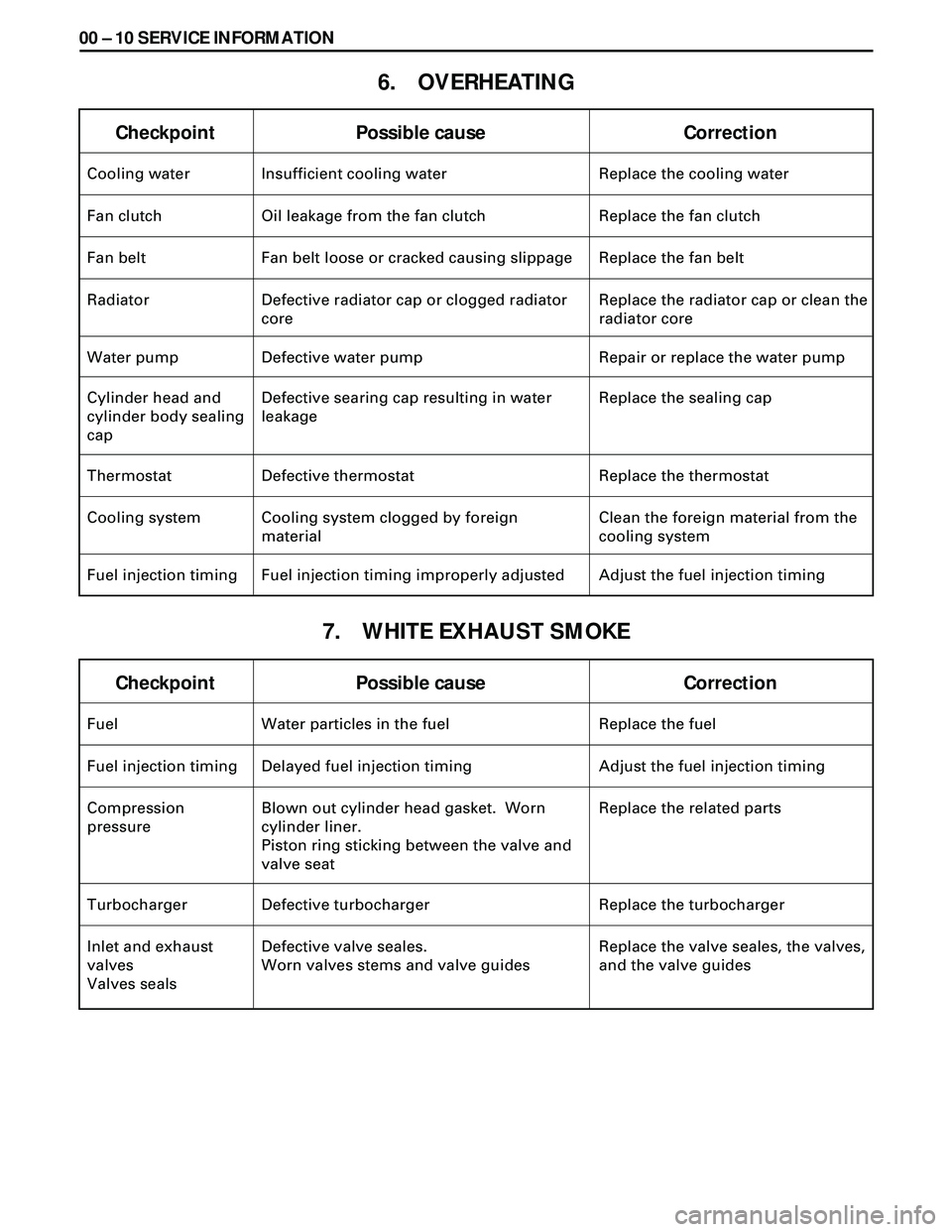
6. OVERHEATING
7. WHITE EXHAUST SMOKE
Checkpoint Possible cause Correction
Fuel Water particles in the fuel Replace the fuel
Fuel injection timing Delayed fuel injection timing Adjust the fuel injection timing
Compression
pressureBlown out cylinder head gasket. Worn
cylinder liner.
Piston ring sticking between the valve and
valve seatReplace the related parts
Turbocharger Defective turbocharger Replace the turbocharger
Inlet and exhaust
valves
Valves sealsDefective valve seales.
Worn valves stems and valve guidesReplace the valve seales, the valves,
and the valve guides
Checkpoint Possible cause Correction
Cooling water Insufficient cooling water Replace the cooling water
Fan clutch Oil leakage from the fan clutch Replace the fan clutch
Fan belt Fan belt loose or cracked causing slippage Replace the fan belt
Radiator Defective radiator cap or clogged radiator
coreReplace the radiator cap or clean the
radiator core
Water pump Defective water pump Repair or replace the water pump
Cylinder head and
cylinder body sealing
capDefective searing cap resulting in water
leakageReplace the sealing cap
Thermostat Defective thermostat Replace the thermostat
Cooling system Cooling system clogged by foreign
materialClean the foreign material from the
cooling system
Fuel injection timing Fuel injection timing improperly adjusted Adjust the fuel injection timing
Page 1512 of 3573

00 Ð 12 SERVICE INFORMATION
10. ABNORMAL ENGINE NOISE
Checkpoint Possible cause Correction
Fuel Fuel unsuitable Replace the fuel
1. ENGINE KNOCKING
2. GAS LEAKAGE NOISE
Exhaust pipes Loosely connected exhaust pipes. Broken
exhaust pipesTighten the exhaust pipe
connections
Replace the exhaust pipes Check to see that the engine has been thoroughly warmed up before begining the troubleshooting
procedure.
Fuel injection timing Fuel injection timing improperly adjusted Adjust the fuel injection timing
Injection nozzle Improper injection nozzle starting pressure
and spray conditionAdjust or replace the injection
nozzle
Compression
pressureBlown out head gasket
Broken piston ringReplace the head gasket or the
piston ring
Injection nozzles
and/or glow plugsLoose injection nozzles and/or glow plugs Replace the washers
Tighten the injection nozzles and/or
the glow plugs
Exhaust manifold Loosely connected exhaust manifold and/or
glow plugsTighten the exhaust manifold
connections
Cylinder head gasket Damaged cylinder head gasket Replace the cylinder head gasket
3. CONTINUOUS NOISE
Fan belt Loose fan belt Readjust the fan belt tension
Cooling fan Loose coling fan Retighten the cooling fan
Water pump bearing Worn or damaged water pump bearing Replace the water pump bearing
Alternator or vacuum
pumpDefective alternator or vacuum pump Repair or replace the alternator or
the vacuum pump
Valve clearance Clearance improperly adjust Adjust the valve clearance
Page 1514 of 3573
00 Ð 14 SERVICE INFORMATION
Condition Possible cause Correction
Engine overheating Low coolant level Replenish
Thermo unit faulty
Faulty thermostat
Faulty coolant unit
Clogged radiator
Faulty radiator cap
Low engine oil level or use of improper
engine oil
Damaged cylinder head gasket
Clogged exhaust system
Loose fan belt
Excessive fuel injected
Improper injection timing
Injection timing improper
Faulty thermostat
Faulty thermostatReplace
Replace
Repair or replace
Clean or replace
Replace
Replenish or change oil
Replenish
Replace
Clean exhaust system or replace
faulty parts
Adjust
Adjust
Adjust
Replace
Replace
Thermo unit faultyReplace Engine overcooling
Too long engine
warm-up time
Adjust
ENGINE COOLING TROUBLE
Page 1617 of 3573
4JG2-NA/4JG2-TURBO ENGINE 6A2 Ð 15
TIMING GEAR
REMOVAL
Preparation:
·Disconnect battery ground cable.
·Drain coolant.
1. P/S Pump Drive Belt
·Loosen P/S pump mounting bolt and adjust bolt,
and remove the drive belt.
2. AC Generator Drive Belt
·Loosen AC Generator mounting bolt (under side)
and adjust plate lock bolt, and remove the drive
belt.
3. Cooling Fan Assembly
·Remove clamp nut, and remove cooling fan asm,
distant pipe, and fan pulley.
4. Crankshaft Damper Pulley
5. Upper Noise Shield Cover
6. Lower Noise Shield Cover
7. Noise Cover Spacer.
8. Timing Gear Case Cover
9. Oil Pipe
10. Idler Gear ÒBÓ and Shaft
1) Measure the camshaft timing gear backlash and the
crenkshaft timing gear backlash before removing the
idler gear.
Page 1651 of 3573

4JG2-NA/4JG2-TURBO ENGINE 6A2 Ð 49
3. Cooling Fan Assembly
·Remove cooling fan asm fixing nuts, cooling fan
asm, fan pulley and center.
4. Radiator Assembly
·Remove bracket and radiator asm.
5. Air Cleaner Cover & Air Duct
6. Intercooler Assembly (4JG2 -T only)
·(Refer to Intercooler removal steps in this section)
7. P/S Pump Drive Belts
·Loosen P/S pump fixing bolts and adjusting bolt
and remove two drive belts.
8. P/S Pump Assembly
·Remove two fixing bolts (front side), a fixing nut
(rear side) and support P/S pump asm with oil
hoses by tying to body side.
9. Engine Ground Cable
·Disconnect ground cable from A/C compressor
bracket.
10. AC Generator Harness
·Disconnect B terminal and harness connector
from AC generator.
11. A/C Compressor Assembly
·Remove A/C compressor fixing bolt (rear under
side of compressor) by using a long extension bar
at under side of wheel arch.
·Disconnect magnetic clutch harness connector.
·Remove fixing bolts (upper and front lower side
of compressor) and set A/C compressor asm with
pipe lines on battery carrier.
12. Vacuum Hose: Vacuum Pump
·Disconnect vacuum hose from vacuum pump.
13. Starter Harness
·Disconnect B terminal and put cable harness close
to chassis side.
·Disconnect S terminal connector.
14. Engine Harness.
·Disconnect engine harness close to engine side.
15. Accelerater Cable
·Loosen locking nut at bracket and disconnect
accelerater cable from injection pump control
lever.
16. Fuel Hoses
·Disconnect fuel hoses from injection pump side
and take care not to spill fuel and enter dust.
17. Engine Ground Cable
·Disconnect ground cable from left rear side of
timing gear case.
Page 1680 of 3573
6C Ð 14 FUEL SYSTEM
INJECTION PUMP ASSEMBLY
Removal Steps
1. Air cleaner cover & air duct
2. Intercooler assembly
3. Radiator assembly
4. Cooling fan assembly
5. P/S pump drive belt
6. AC generator drive belt7. Timing gear
8. Fuel filter assembly
9. Injection pump harness
10. Fuel hose and CSD hose
11. Injection pump Control cable
12. Injection pipe
13. Injection pump assembly
Installation Steps
To install, follow the removal steps in
the reverse order.
Page 1681 of 3573

FUEL SYSTEM 6C Ð 15
REMOVAL
Preparation:
·Disconnect battery ground cable.
·Drain coolant.
1. Air Cleaner Cover & Air Duct
2. Intercooler Assembly (4JG2-T ONLY)
· Refer to Intercooler Assembly removal.
3. Radiator Assembly
·Disconnect upper and lower hoses on the engine
side.
4. Cooling Fan Assembly
·Remove cooling fan asm and remove fan pulley
and spacer.
5. P/S Pump Drive Belt
·Loosen P/S pump lock bolt and adjust bolt remove
two drive belts.
6. AC Generator Drive Belt
·Loosen AC generator mounting bolt (under side)
and adjust, bolt and remove drive belt.
7. Timing Gear
·Refer to Timing Gear Removal
·Remove the loosened nut and fixing bolt and
remove the timing gear.
8.Fuel Filter Assembly
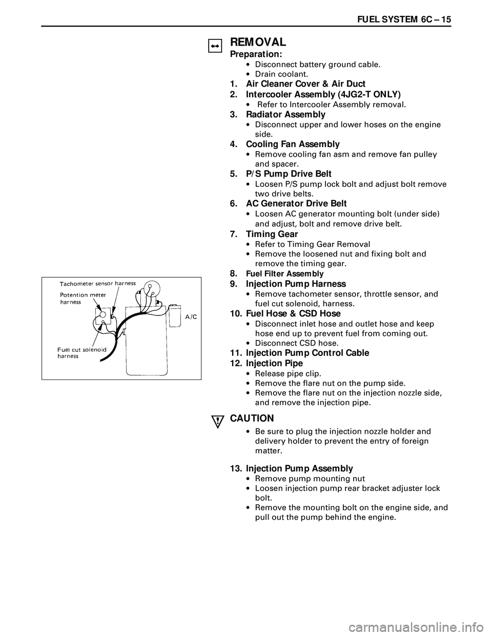
9. Injection Pump Harness
·Remove tachometer sensor, throttle sensor, and
fuel cut solenoid, harness.
10. Fuel Hose & CSD Hose
·Disconnect inlet hose and outlet hose and keep
hose end up to prevent fuel from coming out.
·Disconnect CSD hose.
11. Injection Pump Control Cable
12. Injection Pipe
·Release pipe clip.
·Remove the flare nut on the pump side.
·Remove the flare nut on the injection nozzle side,
and remove the injection pipe.
CAUTION
·Be sure to plug the injection nozzle holder and
delivery holder to prevent the entry of foreign
matter.
13. Injection Pump Assembly
·Remove pump mounting nut
·Loosen injection pump rear bracket adjuster lock
bolt.
·Remove the mounting bolt on the engine side, and
pull out the pump behind the engine.
Page 1682 of 3573

6C Ð 16 FUEL SYSTEM
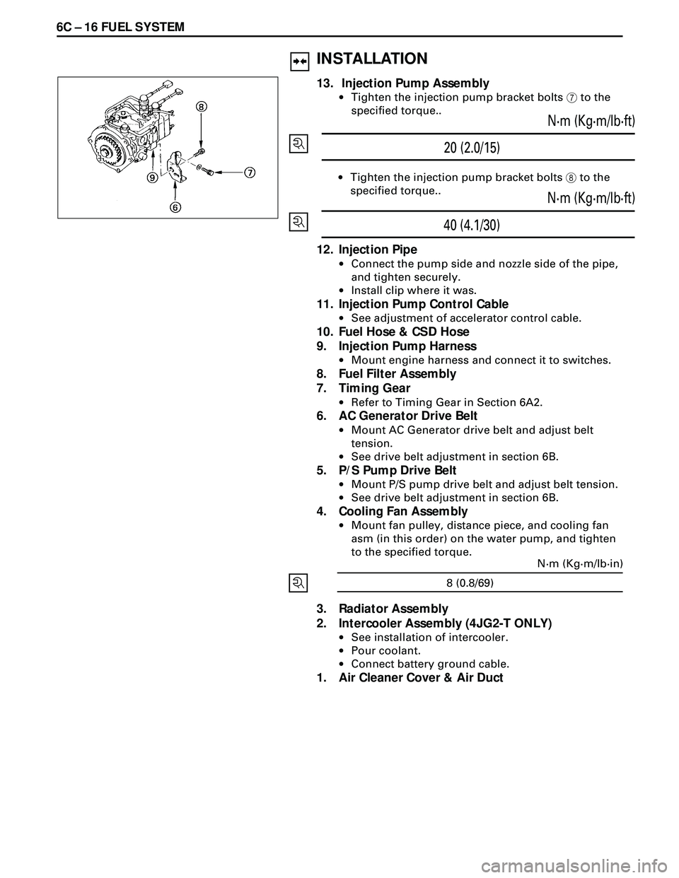
20 (2.0/15)N·m (Kg·m/lb·ft)
·Tighten the injection pump bracket bolts 8 to the
specified torque..
40 (4.1/30)N·m (Kg·m/lb·ft)
12. Injection Pipe
·Connect the pump side and nozzle side of the pipe,
and tighten securely.
·Install clip where it was.
11. Injection Pump Control Cable
·See adjustment of accelerator control cable.
10. Fuel Hose & CSD Hose
9. Injection Pump Harness
·Mount engine harness and connect it to switches.
8. Fuel Filter Assembly
7. Timing Gear
·Refer to Timing Gear in Section 6A2.
6. AC Generator Drive Belt
·Mount AC Generator drive belt and adjust belt
tension.
·See drive belt adjustment in section 6B.
5. P/S Pump Drive Belt
·Mount P/S pump drive belt and adjust belt tension.
·See drive belt adjustment in section 6B.
4. Cooling Fan Assembly
·Mount fan pulley, distance piece, and cooling fan
asm (in this order) on the water pump, and tighten
to the specified torque.
3. Radiator Assembly
2. Intercooler Assembly (4JG2-T ONLY)
·See installation of intercooler.
·Pour coolant.
·Connect battery ground cable.
1. Air Cleaner Cover & Air Duct
INSTALLATION
13. Injection Pump Assembly
·Tighten the injection pump bracket bolts 7 to the
specified torque..
8 (0.8/69)N·m (Kg·m/lb·in)