Page 1492 of 3573
6G±13 ENGINE LUBRICATION
Oil Filter
Removal
1. Disconnect battery ground cable.
2. Drain engine oil.
3. Remove oil filter using 5-8840-0203-0 filter wrench.
Installation
1. Clean filter fitting surface and apply small amount of
engine oil to sealing surface.
2. Install oil filter cartridge by hand until it comes in
contact with sealing surface then rotate additional 2/3
turn to tighten using 5-8840-0203-0 filter wrench.
050RW001
Legend
(1) Oil Pump
(2) Oil Filter
(3) Oil Gallery
(4) From Filter
(5) To Filter
3. Fill engine oil until full level on dipstick.
4. Reconnect battery ground cable.
Page 1494 of 3573
6G±15 ENGINE LUBRICATION
Special Tool
ILLUSTRATIONTOOL NO.
TOOL NAME
5±8840±2287±0
(J±39202)
Installer; Oil pump oil
seal
5±8840±2153±0
(J±37228)
Seal cutter
5±8840±2005±0
(J±29107)
Universal pitman arm
puller
5±8840±0203±0
(J±36390)
Wrench; Oil filter
Page 1511 of 3573

SERVICE INFORMATION 00 Ð 11
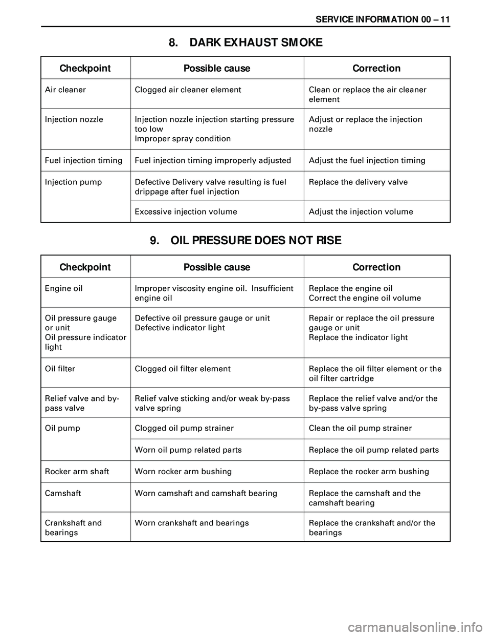
8. DARK EXHAUST SMOKE
Checkpoint Possible cause Correction
Air cleaner Clogged air cleaner element Clean or replace the air cleaner
element
Injection nozzle Injection nozzle injection starting pressure
too low
Improper spray conditionAdjust or replace the injection
nozzle
Fuel injection timing Fuel injection timing improperly adjusted Adjust the fuel injection timing
Injection pump Defective Delivery valve resulting is fuel
drippage after fuel injectionReplace the delivery valve
Excessive injection volume Adjust the injection volume
9. OIL PRESSURE DOES NOT RISE
Checkpoint Possible cause Correction
Engine oil Improper viscosity engine oil. Insufficient
engine oilReplace the engine oil
Correct the engine oil volume
Oil pressure gauge
or unit
Oil pressure indicator
lightDefective oil pressure gauge or unit
Defective indicator lightRepair or replace the oil pressure
gauge or unit
Replace the indicator light
Oil filter Clogged oil filter element Replace the oil filter element or the
oil filter cartridge
Relief valve and by-
pass valveRelief valve sticking and/or weak by-pass
valve springReplace the relief valve and/or the
by-pass valve spring
Oil pump Clogged oil pump strainer Clean the oil pump strainer
Worn oil pump related parts Replace the oil pump related parts
Rocker arm shaft Worn rocker arm bushing Replace the rocker arm bushing
Camshaft Worn camshaft and camshaft bearing Replace the camshaft and the
camshaft bearing
Crankshaft and
bearingsWorn crankshaft and bearings Replace the crankshaft and/or the
bearings
Page 1520 of 3573

00 Ð 20 SERVICE INFORMATION
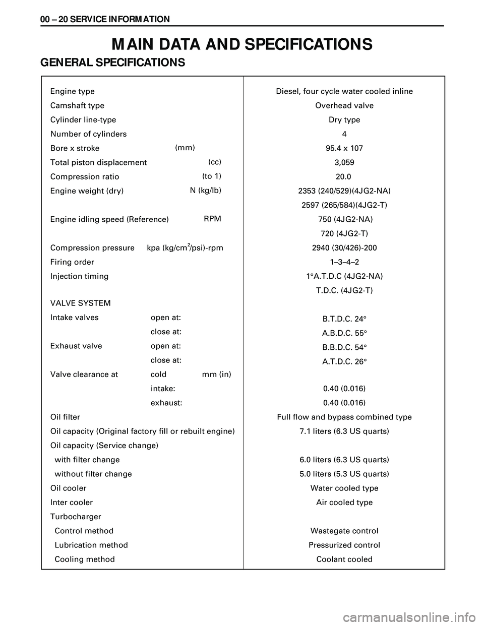
MAIN DATA AND SPECIFICATIONS
GENERAL SPECIFICATIONS
Engine type
Camshaft type
Cylinder line-type
Number of cylinders
Bore x stroke
Total piston displacement
Compression ratio
Engine weight (dry)
Engine idling speed (Reference)
Compression pressure
Firing order
Injection timing
VALVE SYSTEM
Intake valves
Exhaust valve
Valve clearance at
Oil filter
Oil capacity (Original factory fill or rebuilt engine)
Oil capacity (Service change)
with filter change
without filter change
Oil cooler
Inter cooler
Turbocharger
Control method
Lubrication method
Cooling method
(mm)
(cc)
(to 1)
N (kg/lb)
RPM
open at:
close at:
open at:
close at:
cold
intake:
exhaust:mm (in)Diesel, four cycle water cooled inline
Overhead valve
Dry type
4
95.4 x 10⁷
3,059
20.0
2353 (240/529)(4JG2-NA)
2597 (265/584)(4JG2-T)
750 (4JG2-NA)
720 (4JG2-T)
2940 (30/426)-200
1–3–4–2
1¡A.T.D.C (4JG2-NA)
T.D.C. (4JG2-T)
B.T.D.C. 24¡
A.B.D.C. 55¡
B.B.D.C. 54¡
A.T.D.C. 26¡
0.40 (0.016)
0.40 (0.016)
Full flow and bypass combined type
7.1 liters (6.3 US quarts)
6.0 liters (6.3 US quarts)
5.0 liters (5.3 US quarts)
Water cooled type
Air cooled type
Wastegate control
Pressurized control
Coolant cooled kpa (kg/cm /psi)-rpm
2
Page 1527 of 3573

SERVICE INFORMATION 00 Ð 27
SERVICING
Servicing refers to general maintenance procedures to be performed by qualified service personnel.
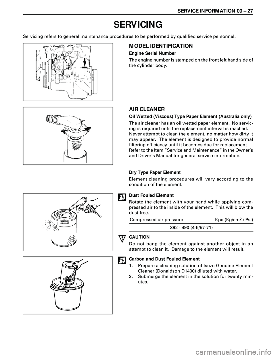
MODEL IDENTIFICATION
Engine Serial Number
The engine number is stamped on the front left hand side of
the cylinder body.
AIR CLEANER
Oil Wetted (Viscous) Type Paper Element (Australia only)
The air cleaner has an oil wetted paper element. No servic-
ing is required until the replacement interval is reached.
Never attempt to clean the element, no matter how dirty it
may appear. The element is designed to provide normal
filtering efficiency until it becomes due for replacement.
Refer to the Item ÒService and MaintenanceÓ in the OwnerÕs
and DriverÕs Manual for general service information.
Dry Type Paper Element
Element cleaning procedures will vary according to the
condition of the element.
Dust Fouled Elemant
Rotate the element with your hand while applying com-
pressed air to the inside of the element. This will blow the
dust free.
392 - 490 (4-5/57-71)
Compressed air pressure
Kpa (Kg/cm2 / Psi)
CAUTION
Do not bang the element against another object in an
attempt to clean it. Damage to the element will result.
Carbon and Dust Fouled Element
1. Prepare a cleaning solution of Isuzu Genuine Element
Cleaner (Donaldson D1400) diluted with water.
2. Submerge the element in the solution for twenty min-
utes.
Page 1528 of 3573

00 Ð 28 SERVICE INFORMATION
3. Remove the element from the solution and rinse it well
with running water.
Water pressure must not exceed 274 Kpa (2.8 kg/cm
2/40
Psi)
4. Dry the element in a well ventilated area.
An electric fan will hasten drying.
NOTE:
Do not use compressed air or an open flame to dry the
element quickly. Damage to the element will result.
It will usually take two or three days for the element to dry
completely. Therefore, it is a good idea to have a spare on
hand to use in the interim.
LUBRICATING SYSTEM
Main Oil Filter (Cartridge Type Paper Element)
Replacement Procedure
1. Loosen the drain plug to drain the engine oil.
2. Wait a few minutes and then retighten the drain plug.
3. Loosen the used oil filter by turning it counterclockwise
with the filter wrench.
4. Clean the oil cooler fitting face.
This will allow the new oil filter to seat properly.
5. Apply a light coat of engine oil to the O-ring.
6. Turn in the new oil filter until the filter O-ring is fitted
against the sealing face.
7. Use the filter wrench to turn in the filter an additional 1
and 1/4 turns.
Filter Wrench: 5-8840-0200-0
8. Check the engine oil level and replenish to the specified
level if required.
0.7 (0.62/0.74)
lit(Imp qt / US qt) Replenishment Engine Oil
9. Start the engine and check for oil leakage from the main
oil filter.
Page 1529 of 3573

SERVICE INFORMATION 00 Ð 29
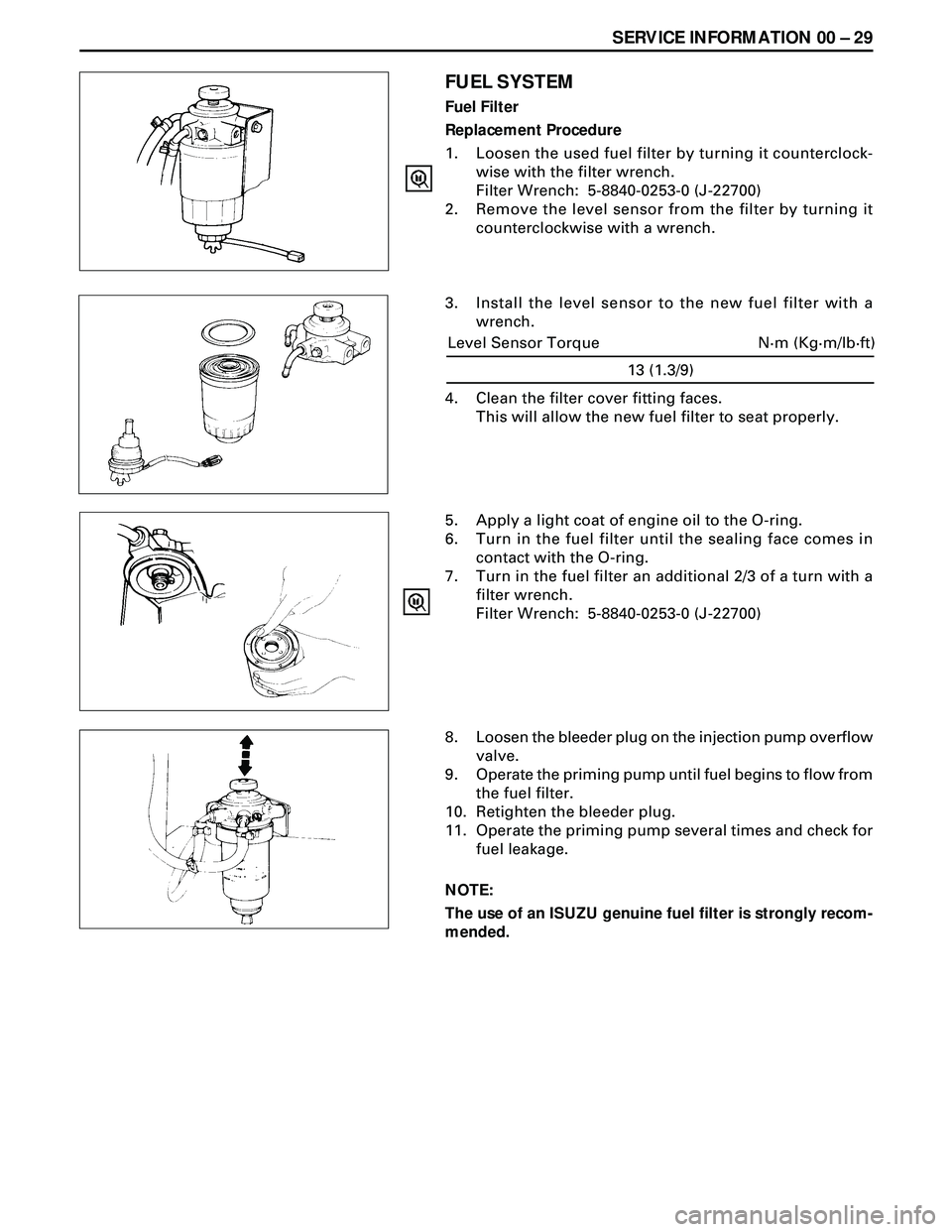
FUEL SYSTEM
Fuel Filter
Replacement Procedure
1. Loosen the used fuel filter by turning it counterclock-
wise with the filter wrench.
Filter Wrench: 5-8840-0253-0 (J-22700)
2. Remove the level sensor from the filter by turning it
counterclockwise with a wrench.
3. Install the level sensor to the new fuel filter with a
wrench.
5. Apply a light coat of engine oil to the O-ring.
6. Turn in the fuel filter until the sealing face comes in
contact with the O-ring.
7. Turn in the fuel filter an additional 2/3 of a turn with a
filter wrench.
Filter Wrench: 5-8840-0253-0 (J-22700)
8. Loosen the bleeder plug on the injection pump overflow
valve.
9. Operate the priming pump until fuel begins to flow from
the fuel filter.
10. Retighten the bleeder plug.
11. Operate the priming pump several times and check for
fuel leakage.
NOTE:
The use of an ISUZU genuine fuel filter is strongly recom-
mended.
13 (1.3/9)
N·m (Kg·m/lb·ft) Level Sensor Torque
4. Clean the filter cover fitting faces.
This will allow the new fuel filter to seat properly.
Page 1547 of 3573
SERVICE INFORMATION 00 Ð 47
SPECIAL TOOLS
ILLUSTRATIONTOOL NAME
5-8840-0200-0
9-8523-1423-0 (J-29760)
5-8840-2033-0
5-8840-9018-0
9-8523-1212-0
5-8840-2313-0
5-8840-2304-0
TOOL NO.
Oil Filter Wrench
Valve Spring Compressor
Valve Stem Oil Seal Installer
Piston Ring Compressor
Valve Guide Replacer
Cylinder Liner Installer
Cylinder Liner Remover Ankle
Cylinder Liner Remover 9-8523-1169-0
5-8840-2675-0
5-8840-2153-0
5-8531-7002-0Compression Gauge
Seal Cutter
Gauge Adapter
�L�H���D�N���� ����
�������� ���� �������� ����