Page 109 of 3573
1A Ð 14 HEATING AND VENTILATION
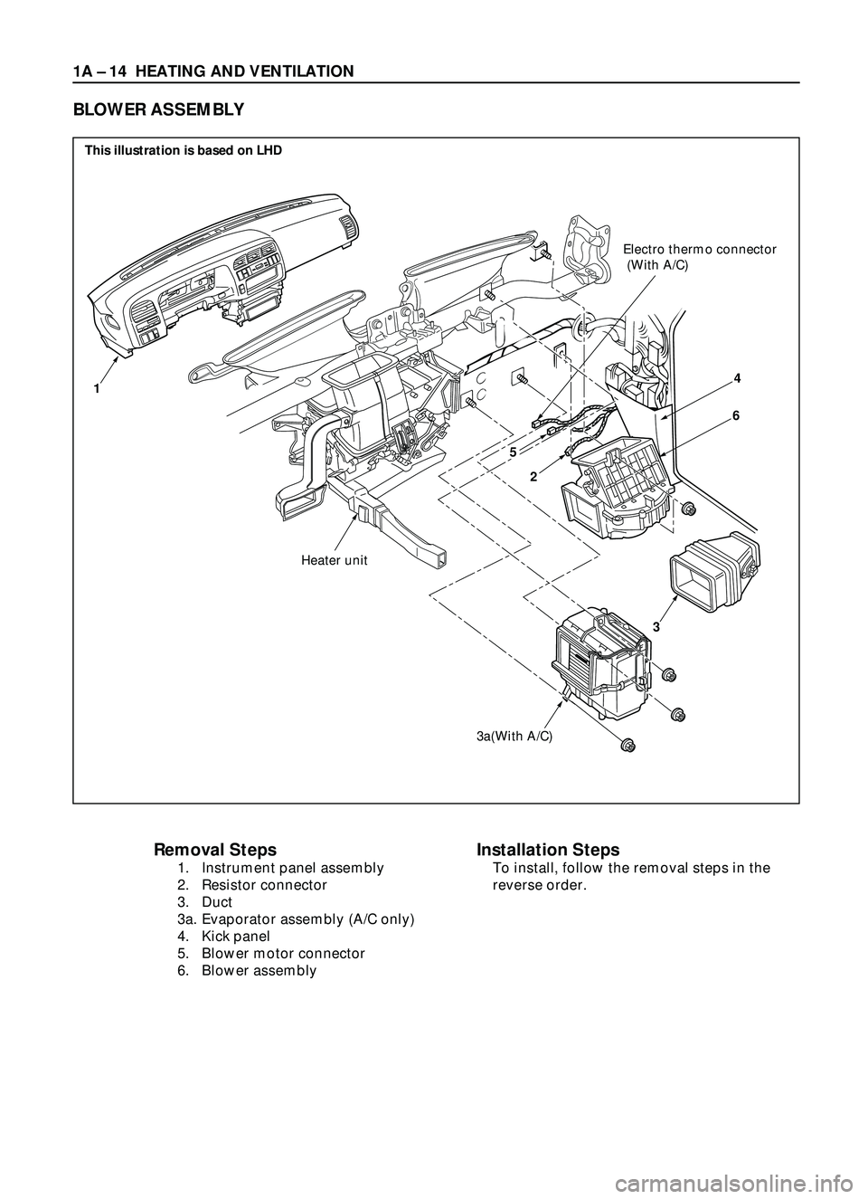
Removal Steps
1. Instrument panel assembly
2. Resistor connector
3. Duct
3a. Evaporator assembly (A/C only)
4. Kick panel
5. Blower motor connector
6. Blower assembly
Installation Steps
To install, follow the removal steps in the
reverse order.
BLOWER ASSEMBLY
2
3a(With A/C)
3
Heater unit
Electro thermo connector
(With A/C)
14
6
5
This illustration is based on LHD
Page 115 of 3573
1A Ð 20 HEATING AND VENTILATION
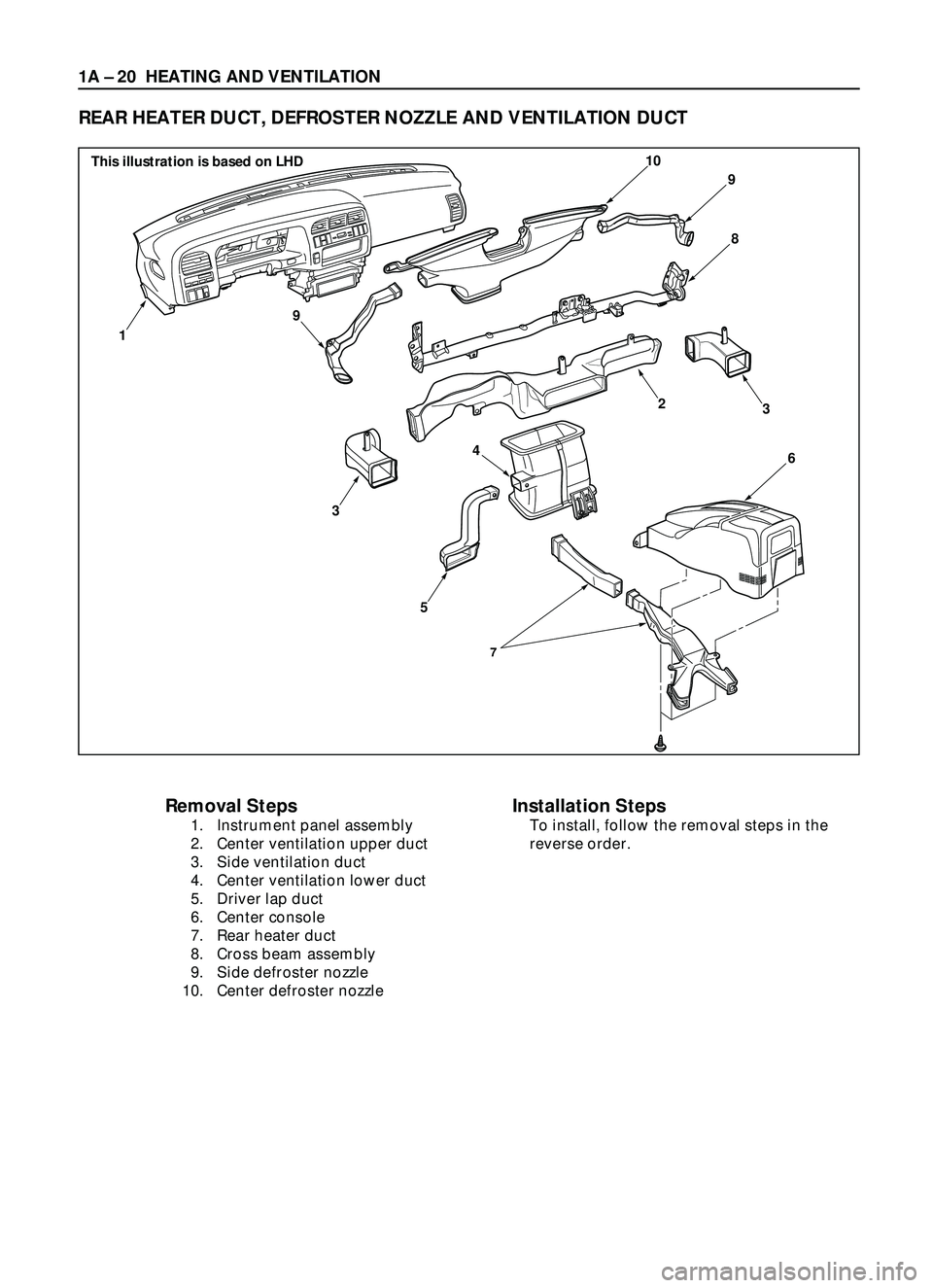
REAR HEATER DUCT, DEFROSTER NOZZLE AND VENTILATION DUCT
Removal Steps
1. Instrument panel assembly
2. Center ventilation upper duct
3. Side ventilation duct
4. Center ventilation lower duct
5. Driver lap duct
6. Center console
7. Rear heater duct
8. Cross beam assembly
9. Side defroster nozzle
10. Center defroster nozzle
Installation Steps
To install, follow the removal steps in the
reverse order.
7
9
9
10
8
6
3
5
1
3
4
2
This illustration is based on LHD
Page 116 of 3573
HEATING AND VENTILATION 1A Ð 21
INSTALLATION
To install, follow the removal steps in the reverse order,
noting the following point:
1. Connect each duct and nozzle securely leaving no
clearance between them and making no improper
matching.
REMOVAL
Preparation:
Disconnect the battery ground cable
1. Instrument panel assembly
·Refer to Section 10 ÒBODYÓ for INSTRUMENT
PANEL ASSEMBLY removal procedure.
2. Center ventilation upper duct
3. Side ventilation duct
4. Center ventilation lower duct
5. Driver lap duct
6. Center console
7. Rear heater duct
·Refer to Section 10 ÒBODYÓ for CONSOLES
removal procedure.
8. Cross beam assembly
·Refer to Section 10 ÒBODYÓ for CROSS BEAM
ASSEMBLY removal procedure.
9. Side defroster nozzle
10. Center defroster nozzle
Page 120 of 3573
HEATING AND VENTILATION 1A Ð 25
REMOVAL
Preparation:
Disconnect the battery ground cable
1. Front console assembly
2. Lower cluster assembly
3. Glove box
4. Instrument panel passenger lower cover
5. Instrument panel driver lower cover
6. Meter cluster assembly
Refer to Section 10 ÒBODYÓ for INSTRUMENT PANEL
ASSEMBLY removal procedure.
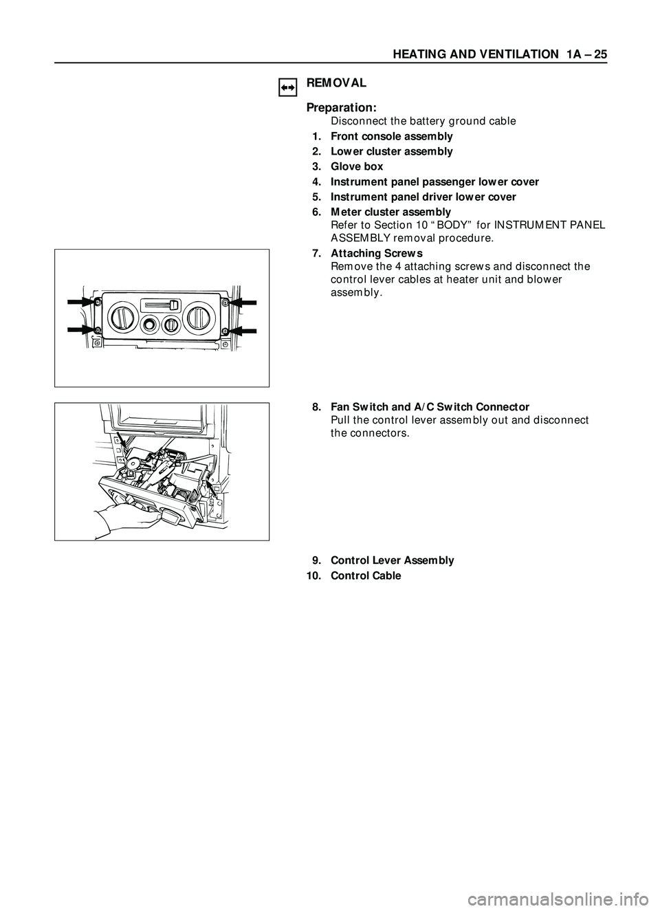
7. Attaching Screws
Remove the 4 attaching screws and disconnect the
control lever cables at heater unit and blower
assembly.
8. Fan Switch and A/C Switch Connector
Pull the control lever assembly out and disconnect
the connectors.
9. Control Lever Assembly
10. Control Cable
Page 121 of 3573
1A Ð 26 HEATING AND VENTILATION
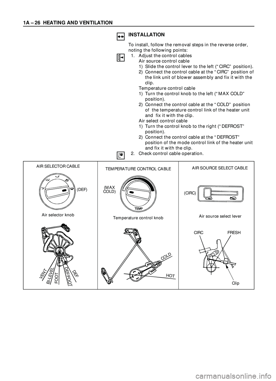
INSTALLATION
To install, follow the removal steps in the reverse order,
noting the following points:
1. Adjust the control cables
Air source control cable
1) Slide the control lever to the left (ÒCIRCÓ position).
2) Connect the control cable at the ÒCIRCÓ position of
the link unit of blower assembly and fix it with the
clip.
Temperature control cable
1) Turn the control knob to the left (ÒMAX COLDÓ
position).
2) Connect the control cable at the ÒCOLDÓ position
of the temperature control link of the heater unit
and fix it with the clip.
Air select control cable
1) Turn the control knob to the right (ÒDEFROSTÓ
position).
2) Connect the control cable at the ÒDEFROSTÓ
position of the mode control link of the heater unit
and fix it with the clip.
2. Check control cable operation.
AIR SELECTOR CABLE
Air selector knob
VENT
BI-LEVELFOOT
DEF/FOOTDEF
(DEF)
TEMPERATURE CONTROL CABLE
Temperature control knob
COLD
HOT
(MAX
COLD)
AIR SOURCE SELECT CABLE
Air source select lever (CIRC)
CIRC FRESH
Clip
Page 123 of 3573
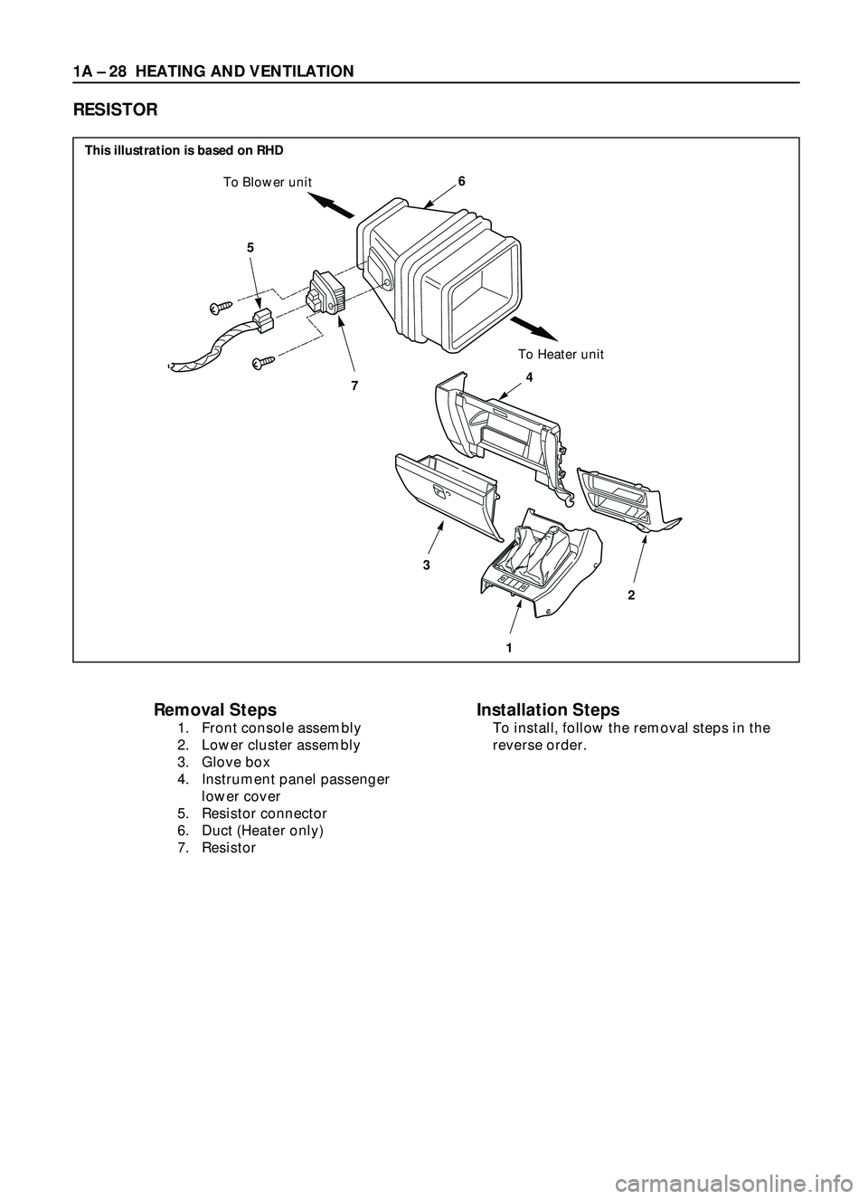
1A Ð 28 HEATING AND VENTILATION
5
7
6To Blower unit
To Heater unit
34
12
Removal Steps
1. Front console assembly
2. Lower cluster assembly
3. Glove box
4. Instrument panel passenger
lower cover
5. Resistor connector
6. Duct (Heater only)
7. Resistor
Installation Steps
To install, follow the removal steps in the
reverse order.
RESISTOR
This illustration is based on RHD
Page 124 of 3573
HEATING AND VENTILATION 1A Ð 29
REMOVAL
Preparation:
Disconnect the battery ground cable
1. Front console assembly
2. Lower cluster assembly
3. Glove box
4. Instrument panel passenger lower cover
Refer to Section 10 ÒBODYÓ for INSTRUMENT PANEL
ASSEMBLY removal procedure.
5. Resistor connector
6. Duct (Heater only)
7. Resistor
INSTALLATION
To install, follow the removal steps in the reverse order.
Page 125 of 3573
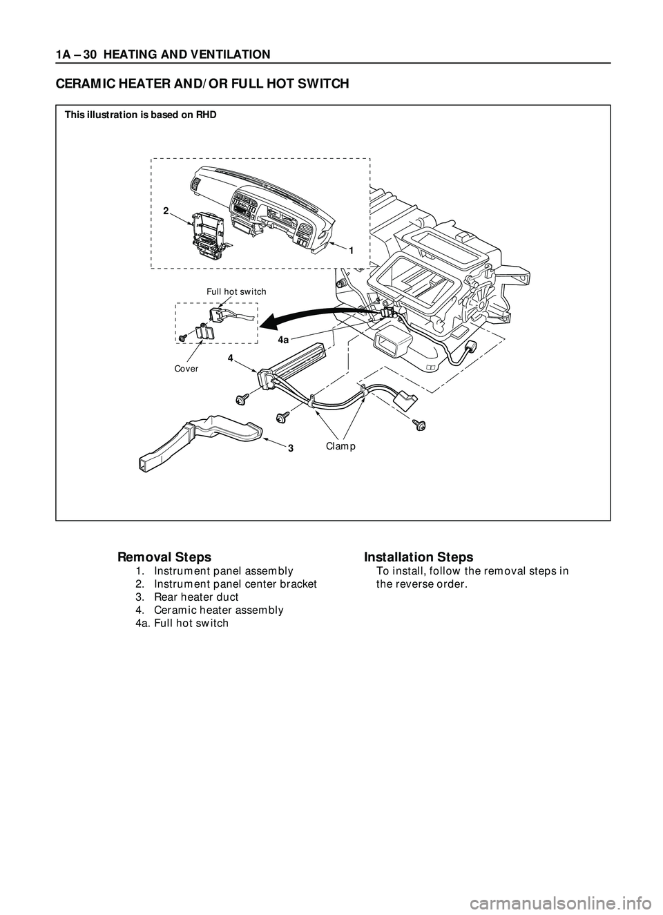
1A Ð 30 HEATING AND VENTILATION
4
4a
3
Full hot switch
Cover
Clamp
22
0
25
30AUTOA
/
CO
F
FAUTOLOHI
1
�y
Removal Steps
1. Instrument panel assembly
2. Instrument panel center bracket
3. Rear heater duct
4. Ceramic heater assembly
4a. Full hot switch
CERAMIC HEATER AND/OR FULL HOT SWITCH
Installation Steps
To install, follow the removal steps in
the reverse order.
This illustration is based on RHD