Page 3323 of 3573
SEATS8G±11
15. Remove the back board assembly(4).
�Remove the board fixing screws.
�Pull the back board downward and remove the
board from the seat back frame(5).
750RW008
16. Remove the reclining device(7).
�Remove the device lower side fixing bolt in order to
separate the seat back from the seat cushion.
�Disconnect the seat heater connector.
�Remove the trim cover(6) hog rings from the
backside of the seat back assembly.
�Turn up the seat back trim cover to remove the
reclining device upper side fixing bolt.
�Disconnect the connecting shaft and the reclining
device connectors.
750RW009
17. Remove the seat back assembly.
18. Remove the guide holder(8).
�Remove the trim cover fixing hog rings(9) from the
backside of the seat back assembly.
�Hold the tip end of the guide holder and pull the
holder out from the seat back assembly.
750RW010
19. Remove the trim cover.
�Remove the trim cover hog rings from the backside
of the seat back.
�With close attention paid to the hog rings and the
wire which connect the trim cover and pad & frame
assembly, remove the trim cover while turning it up.
20. Remove the seat heater.
21. Remove the pad assembly.
22. Remove the frame assembly.
23. Remove the outer lower cover.
24. Remove the inner lower cover.
25. Remove the adjuster assembly.
�Disconnect the connectors and remove the fixing
bolts.
Page 3324 of 3573
8G±12SEATS
�Remove the power seat harness from the adjuster
assembly.
26. Remove the seat cushion assembly.
27. Remove the trim cover.
�Remove the trim cover hog rings from the backside
of the seat cushion assembly.
�With close attention paid to the hog rings and the
wire which connect the trim cover and the pad &
frame assembly, remove the trim cover while
turning it up.28. Remove the seat heater.
29. Remove the frame assembly.
30. Remove the pad assembly.
Reassembly
To reassemble, follow the disassembly steps in the
reverse order, noting the following point.
1. Tighten the fixing bolts to the specified torque.
�Refer to the Torque Specifications in this section.
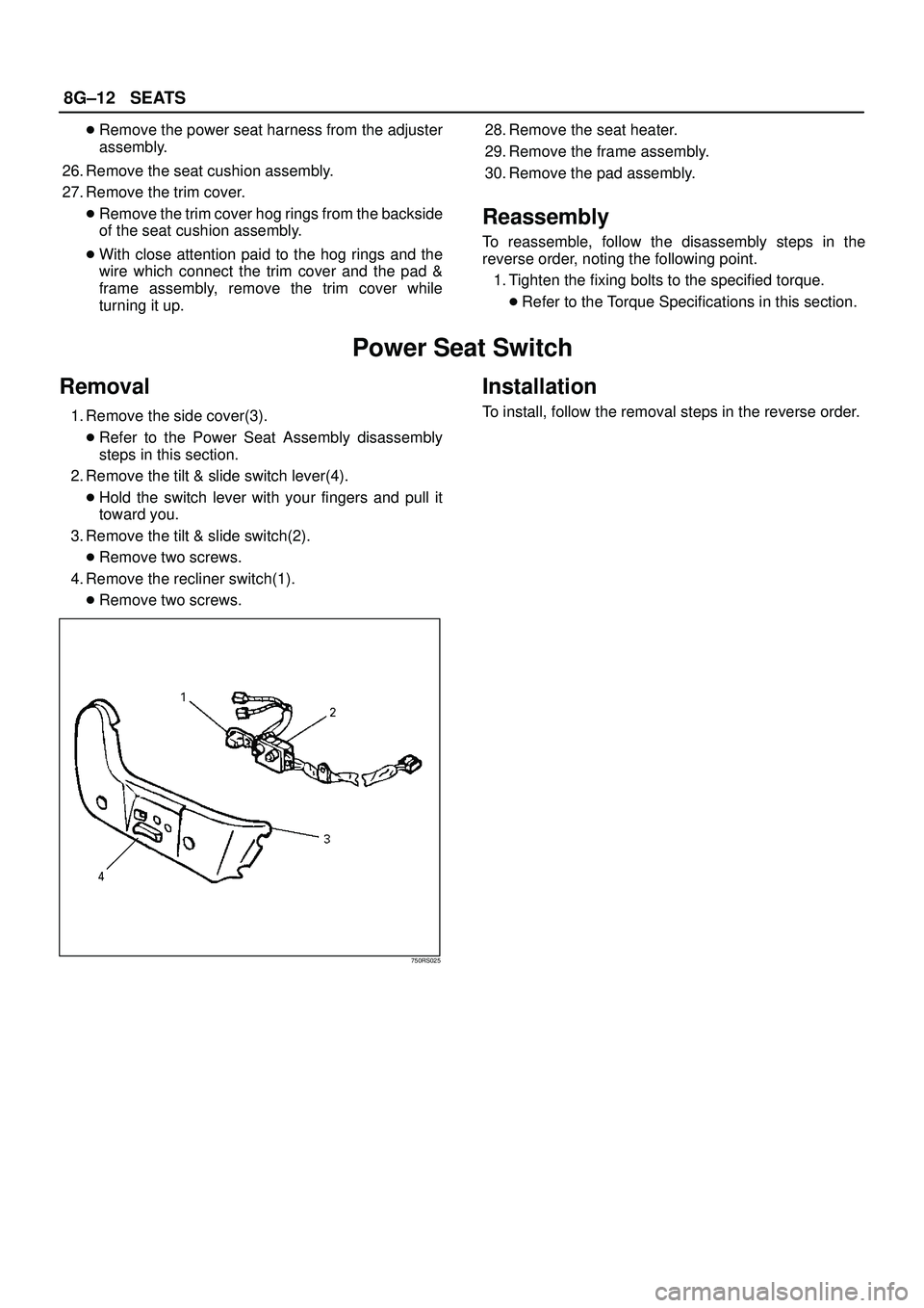
Power Seat Switch
Removal
1. Remove the side cover(3).
�Refer to the Power Seat Assembly disassembly
steps in this section.
2. Remove the tilt & slide switch lever(4).
�Hold the switch lever with your fingers and pull it
toward you.
3. Remove the tilt & slide switch(2).
�Remove two screws.
4. Remove the recliner switch(1).
�Remove two screws.
750RS025
Installation
To install, follow the removal steps in the reverse order.
Page 3326 of 3573
8G±14SEATS
Seat Heater System
General Description
The circuit consists of the starter switch, seat heater
switch and the heat unit.
The seat heater is provided in driver's and front
passenger seats (as option).
When the seat heater switch is ON, the seat heat built in
the seat back and cushion is switched on to warm the
seats.
To prevent the seats from being overheated, the circuit is
fitted with a thermostat.
Seat Heater Switch Removal and
Installation
Refer to the Seat Heater Switch removal and installation
steps in Lighting System section.
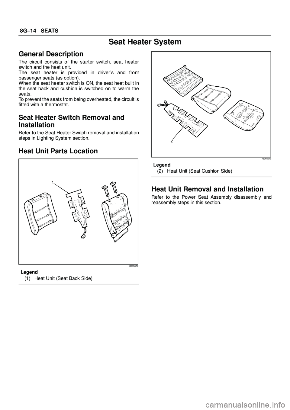
Heat Unit Parts Location
750RS018
Legend
(1) Heat Unit (Seat Back Side)
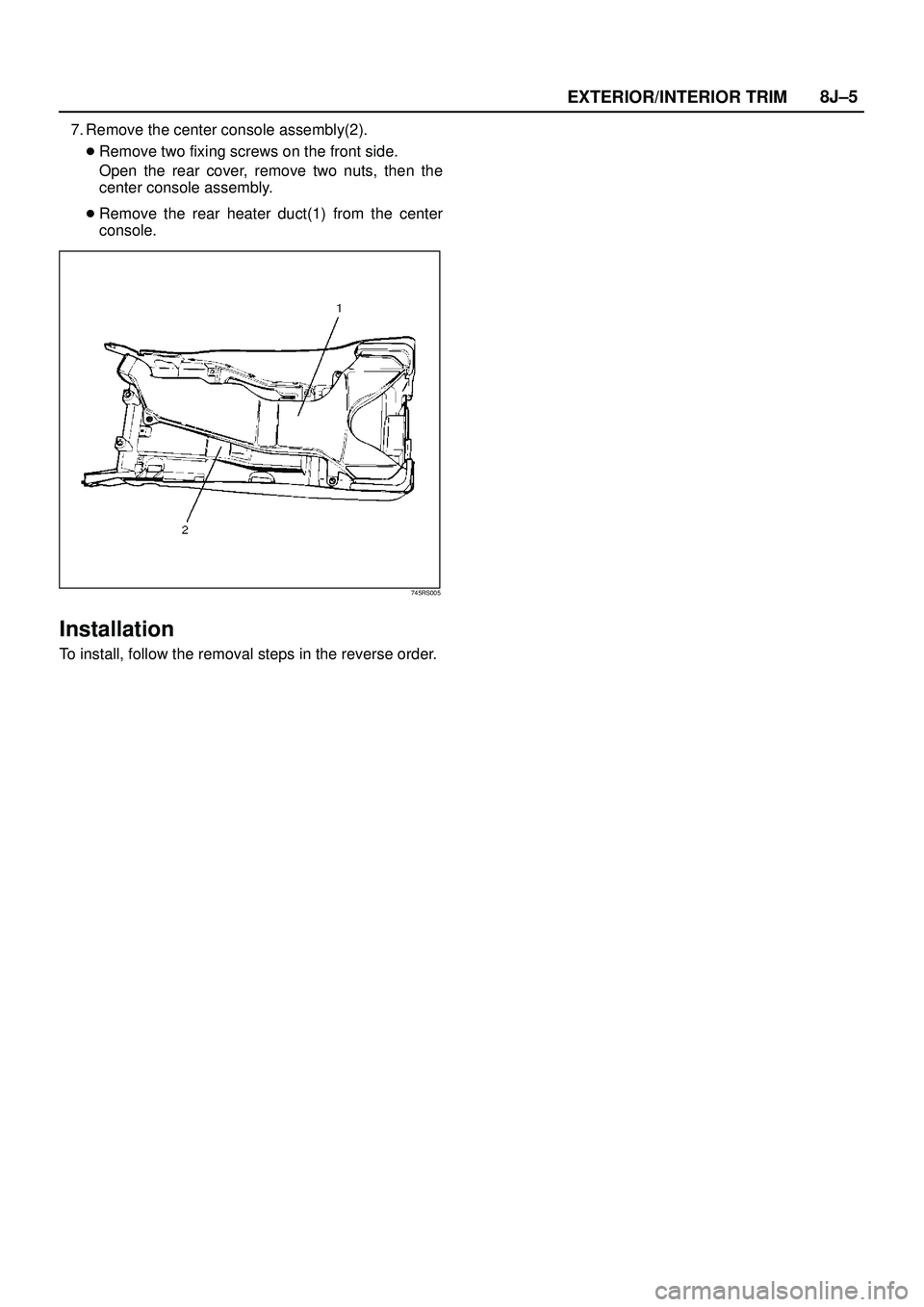
750RS019
Legend
(2) Heat Unit (Seat Cushion Side)
Heat Unit Removal and Installation
Refer to the Power Seat Assembly disassembly and
reassembly steps in this section.
Page 3384 of 3573
EXTERIOR/INTERIOR TRIM8J±5
7. Remove the center console assembly(2).
�Remove two fixing screws on the front side.
Open the rear cover, remove two nuts, then the
center console assembly.
�Remove the rear heater duct(1) from the center
console.
745RS005
Installation
To install, follow the removal steps in the reverse order.
Page 3417 of 3573
8J±38EXTERIOR/INTERIOR TRIM
Power Door Mirror System
General Description
The circuit consists of the starter switch, door mirror
control switch, folding switch, defogger switch and door
mirrors on both sides.
The door mirror switch consists of the control switch,
folding switch and defogger switch.
When the control switch is operated with the starter
switch at either ªACCº or ªONº position, the motors
incorporated in the door mirrors on both sides rotates to
allow the horizontal and vertical adjustment of mirror
angles.
The folding switch can be used to fold the mirror and
return it to its original position.
When turning on the door mirror defogger switch with the
starter switch at ªONº position, built-in heater in the mirror
is activated to perform the defogger function.
Door Mirror Switch Assembly (Con-
trol Switch, Folding Switch and De-
fogger Switch) Removal
1. Disconnect the battery ground cable.
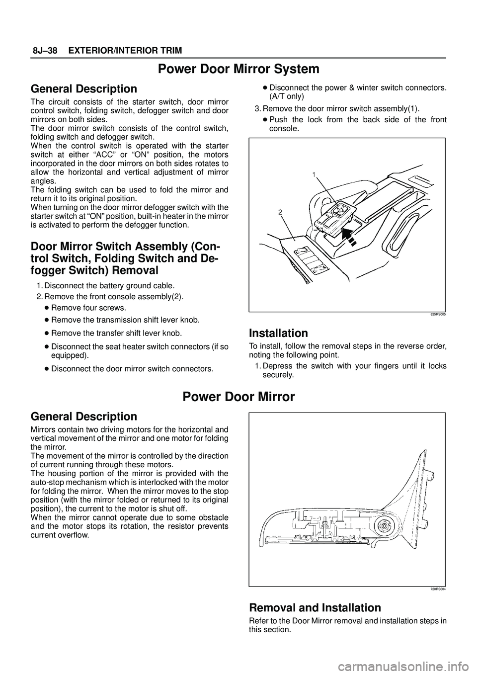
2. Remove the front console assembly(2).
�Remove four screws.
�Remove the transmission shift lever knob.
�Remove the transfer shift lever knob.
�Disconnect the seat heater switch connectors (if so
equipped).
�Disconnect the door mirror switch connectors.�Disconnect the power & winter switch connectors.
(A/T only)
3. Remove the door mirror switch assembly(1).
�Push the lock from the back side of the front
console.
825RS005
Installation
To install, follow the removal steps in the reverse order,
noting the following point.
1. Depress the switch with your fingers until it locks
securely.
Power Door Mirror
General Description
Mirrors contain two driving motors for the horizontal and
vertical movement of the mirror and one motor for folding
the mirror.
The movement of the mirror is controlled by the direction
of current running through these motors.
The housing portion of the mirror is provided with the
auto-stop mechanism which is interlocked with the motor
for folding the mirror. When the mirror moves to the stop
position (with the mirror folded or returned to its original
position), the current to the motor is shut off.
When the mirror cannot operate due to some obstacle
and the motor stops its rotation, the resistor prevents
current overflow.
720RS004
Removal and Installation
Refer to the Door Mirror removal and installation steps in
this section.