Page 1470 of 3573
6E±353 ENGINE DRIVEABILITY AND EMISSIONS
ILLUSTRATIONTOOL NO.
TOOL NAME
5-8840-0285-0
(J 39200)
High Impedance
Multimeter (Digital
Voltmeter ± DVM)
(1) PCMCIA Card
(2) RS232 Loop Back
Connector
(3) SAE 16/19 Adapter
(4) DLC Cable
(5) TECH±2
5-8840-0607-0
(J 34142-B)
Unpowered Test Light
5-8840-0385-0
(J 35616-A/BT-8637)
Connector Test
Adapter Kit
5-8840-0383-0
(J 26792/BT-7220-1)
Spark Tester
5-8840-0279-0
(J 23738-A)
Vacuum Pump with
Gauge common tool
ILLUSTRATIONTOOL NO.
TOOL NAME
BT-8515
Exhaust Back Pressure
Tester or common tool
5-8840-2640-0
(J 39194-B)
Heated Oxygen Sensor
Wrench
5-8840-0632-0
(J 35689-A)
Terminal Remover
5-8840-0388-0
(J 28742-A)
Weather Pack II
Terminal Remover
5-8840-2635-0
(J 39021-90)
Injector Switch Box
5-8840-2636-0
(J 39021-65)
Injector Test Light
Page 1475 of 3573

6F±4ENGINE EXHAUST
Front Exhaust Pipe
Front Exhaust Pipe and Associated Parts
150RW063
Legend
(1) Front Exhaust Pipe RH Fixing Nuts
(2) Front Exhaust Pipe RH Fixing Bolts and Nuts
(3) O
2 Sensor Terminal Connector (for IGM)
(4) Front Exhaust Pipe LH Fixing Nuts(5) Front Exhaust Pipe LH Fixing Bolts and Nuts
(6) Front Exhaust Pipe LH
(7) Front Exhaust Pipe RH
(8) Three way Exhaust Pipe Fixing Bolts and Nuts
Removal
1. Disconnect battery ground cable.
2. Raise the vehicle and support with suitable safety
stands.
3. Disconnect O
2 sensor harness connector (3).
4. Remove front exhaust pipe fixing nuts and three way
Exhaust Pipe Fixing Bolts and Nuts (2)(5)(8).
5. Remove front exhaust pipe fixing three stud nuts from
exhaust manifold (1)(4).
6. Remove front exhaust pipe (6)(7).
Installation
1. Install front exhaust pipe (6)(7) and tighten three stud
nuts (1)(4) and nuts (2)(5)(8) to the specified torque.
Torque
Stud Nuts : 67 N´m (6.8 Kg´m/49 lb ft)
Nuts : 43 N´m (4.3 Kg´m/32 lb ft)
2. Reconnect O
2 sensor harness connector (3).
Page 1500 of 3573
6J±2
INDUCTION
Air Cleaner Element
Removal
1. Remove positive ventilation hose from connector(1).
2. Remove intake air temperature sensor(2).
3. Remove air flow sensor(3).
4. Remove air cleaner duct cover(4).
5. Remove air cleaner element(5).
130RW003
Inspection
Check the air cleaner element for damage or dust
clogging. Replace if it is damaged, or clean if it is clogged.
Cleaning Method
Tap the air cleaner element gently so as not to damage
the paper element, or clean the element by blowing with
compressed air of about 490 kPa (71 psi) from the clean
side if it is extremely dirty.
130RW002
Installation
1. Install air cleaner element(5).
2. Attach the air cleaner duct cover (4) to the body
completely, then clamp it with the clip.
3. Install mass air flow sensor(3).
4. Install air temperature sensor(2).
5. Connect positive crankcase ventilation hose to
connector(1).
For General Export Model
130RW003
For Isuzu General Motors (IGM) Model
130RW006
Page 1505 of 3573

SERVICE INFORMATION 00 Ð 5
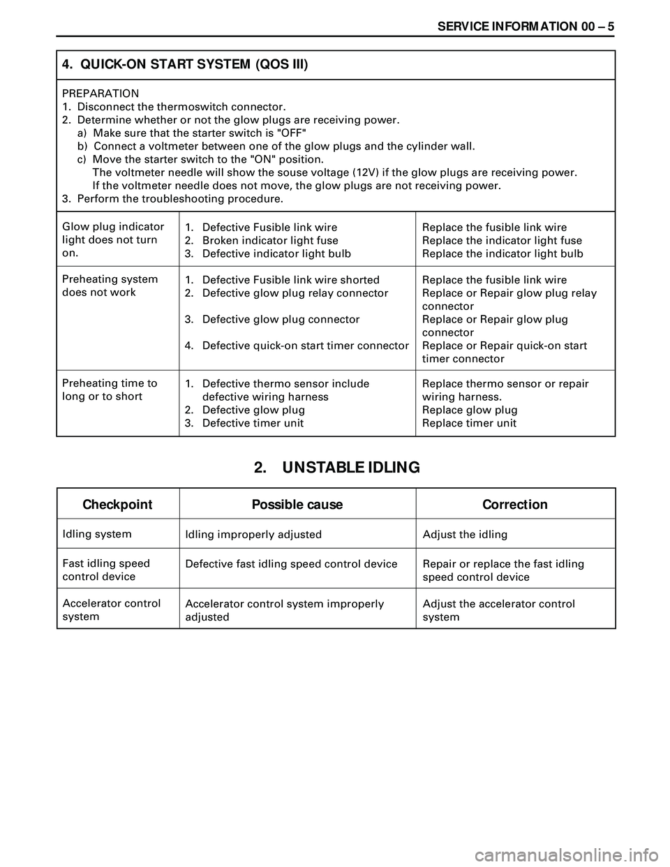
Idling improperly adjusted Adjust the idling Idling system
Checkpoint Possible cause Correction
Defective fast idling speed control device Repair or replace the fast idling
speed control device Fast idling speed
control device
Accelerator control system improperly
adjustedAdjust the accelerator control
system Accelerator control
system
2. UNSTABLE IDLING
4. QUICK-ON START SYSTEM (QOS III)
PREPARATION
1. Disconnect the thermoswitch connector.
2. Determine whether or not the glow plugs are receiving power.
a) Make sure that the starter switch is "OFF"
b) Connect a voltmeter between one of the glow plugs and the cylinder wall.
c) Move the starter switch to the "ON" position.
The voltmeter needle will show the souse voltage (12V) if the glow plugs are receiving power.
If the voltmeter needle does not move, the glow plugs are not receiving power.
3. Perform the troubleshooting procedure.
1.
2.
3.Replace the fusible link wire
Replace the indicator light fuse
Replace the indicator light bulb Glow plug indicator
light does not turn
on.Defective Fusible link wire
Broken indicator light fuse
Defective indicator light bulb
1.
2.
3.
4.Replace the fusible link wire
Replace or Repair glow plug relay
connector
Replace or Repair glow plug
connector
Replace or Repair quick-on start
timer connector Preheating system
does not workDefective Fusible link wire shorted
Defective glow plug relay connector
Defective glow plug connector
Defective quick-on start timer connector
1.
2.
3.Replace thermo sensor or repair
wiring harness.
Replace glow plug
Replace timer unit Preheating time to
long or to shortDefective thermo sensor include
defective wiring harness
Defective glow plug
Defective timer unit
Page 1529 of 3573

SERVICE INFORMATION 00 Ð 29
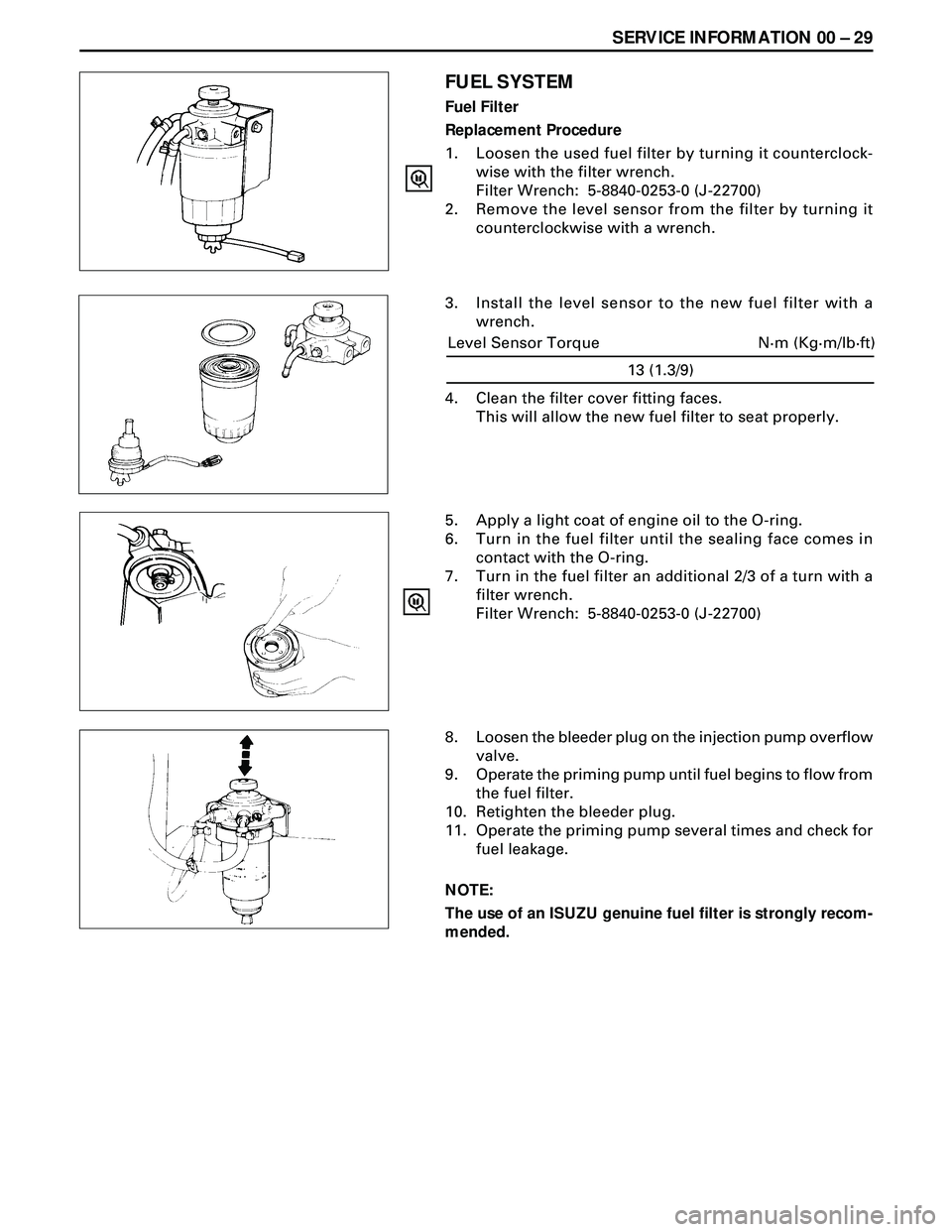
FUEL SYSTEM
Fuel Filter
Replacement Procedure
1. Loosen the used fuel filter by turning it counterclock-
wise with the filter wrench.
Filter Wrench: 5-8840-0253-0 (J-22700)
2. Remove the level sensor from the filter by turning it
counterclockwise with a wrench.
3. Install the level sensor to the new fuel filter with a
wrench.
5. Apply a light coat of engine oil to the O-ring.
6. Turn in the fuel filter until the sealing face comes in
contact with the O-ring.
7. Turn in the fuel filter an additional 2/3 of a turn with a
filter wrench.
Filter Wrench: 5-8840-0253-0 (J-22700)
8. Loosen the bleeder plug on the injection pump overflow
valve.
9. Operate the priming pump until fuel begins to flow from
the fuel filter.
10. Retighten the bleeder plug.
11. Operate the priming pump several times and check for
fuel leakage.
NOTE:
The use of an ISUZU genuine fuel filter is strongly recom-
mended.
13 (1.3/9)
N·m (Kg·m/lb·ft) Level Sensor Torque
4. Clean the filter cover fitting faces.
This will allow the new fuel filter to seat properly.
Page 1537 of 3573

SERVICE INFORMATION 00 Ð 37
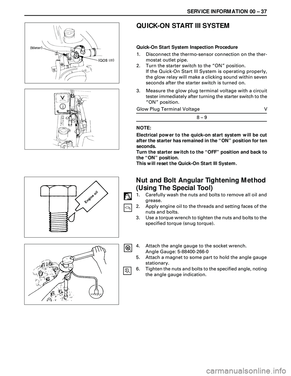
3. Measure the glow plug terminal voltage with a circuit
tester immediately after turning the starter switch to the
ÒONÓ position.
8 – 9
V Glow Plug Terminal Voltage
QUICK-ON START III SYSTEM
Quick-On Start System Inspection Procedure
1. Disconnect the thermo-sensor connection on the ther-
mostat outlet pipe.
2. Turn the starter switch to the ÒONÓ position.
If the Quick-On Start III System is operating properly,
the glow relay will make a clicking sound within seven
seconds after the starter switch is turned on.
NOTE:
Electrical power to the quick-on start system will be cut
after the starter has remained in the ÒONÓ position for ten
seconds.
Turn the starter switch to the ÒOFFÓ position and back to
the ÒONÓ position.
This will reset the Quick-On Start III System.
Nut and Bolt Angular Tightening Method
(Using The Special Tool)
1. Carefully wash the nuts and bolts to remove all oil and
grease.
2. Apply engine oil to the threads and setting faces of the
nuts and bolts.
3. Use a torque wrench to tighten the nuts and bolts to the
specified torque (snug torque).
4. Attach the angle gauge to the socket wrench.
Angle Gauge: 5-88400-266-0
5. Attach a magnet to some part to hold the angle gauge
stationary.
6. Tighten the nuts and bolts to the specified angle, noting
the angle gauge indication.
Page 1681 of 3573

FUEL SYSTEM 6C Ð 15
REMOVAL
Preparation:
·Disconnect battery ground cable.
·Drain coolant.
1. Air Cleaner Cover & Air Duct
2. Intercooler Assembly (4JG2-T ONLY)
· Refer to Intercooler Assembly removal.
3. Radiator Assembly
·Disconnect upper and lower hoses on the engine
side.
4. Cooling Fan Assembly
·Remove cooling fan asm and remove fan pulley
and spacer.
5. P/S Pump Drive Belt
·Loosen P/S pump lock bolt and adjust bolt remove
two drive belts.
6. AC Generator Drive Belt
·Loosen AC generator mounting bolt (under side)
and adjust, bolt and remove drive belt.
7. Timing Gear
·Refer to Timing Gear Removal
·Remove the loosened nut and fixing bolt and
remove the timing gear.
8.Fuel Filter Assembly
9. Injection Pump Harness
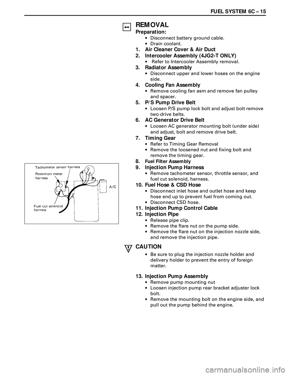
·Remove tachometer sensor, throttle sensor, and
fuel cut solenoid, harness.
10. Fuel Hose & CSD Hose
·Disconnect inlet hose and outlet hose and keep
hose end up to prevent fuel from coming out.
·Disconnect CSD hose.
11. Injection Pump Control Cable
12. Injection Pipe
·Release pipe clip.
·Remove the flare nut on the pump side.
·Remove the flare nut on the injection nozzle side,
and remove the injection pipe.
CAUTION
·Be sure to plug the injection nozzle holder and
delivery holder to prevent the entry of foreign
matter.
13. Injection Pump Assembly
·Remove pump mounting nut
·Loosen injection pump rear bracket adjuster lock
bolt.
·Remove the mounting bolt on the engine side, and
pull out the pump behind the engine.
Page 1719 of 3573
QOS III PREHEATING SYSTEM 6D6 Ð 1
PAGE
General Description ........................................................................................................ 6D6- 1
System Diagram .............................................................................................................. 6D6- 2
GENERAL DESCRIPTION
QOS III preheating system features a quick-on glow
plug with thermometer control of the glowing time
and the afterglow time function.
The system consists of a controller, indicator lamp,
thermosensor, vehicle speedsensor, dropping
resistor, relay (2 pcs), and temperature self-control
type glow plug (4 pcs).With the employment of the thermosensor, the
glow time changes according to the engine coolant
temperature, thus allowing optimum starting
conditions to be obtained.
The afterglow time function is controlled by
thermosensor, vehicle speed sensor, and the
engine runstall sensor (charge relay).
SECTION 6D6
QOSIII PREHEATING SYSTEM
CONTENTS