Page 2265 of 3573

7A1±20
TRANSMISSION CONTROL SYSTEM (4L30±E)
821RW263
810RT022
PIN 1 ± (Not used)
PIN 2 ± J1850 Bus + L line on 2±wire systems, or
single wire (Class 2)
PIN 3 ± (Not used)
PIN 4 ± Chassis ground pin
PIN 5 ± Signal ground pin
PIN 6 ± PCM diagnostic enable
PIN 7 ± (Not used)
PIN 8 ± (Not used)
PIN 9 ± Primary UART
PIN 10 ± (Not used)
PIN 11 ± (Not used)
PIN 12 ± ABS diagnostic or CCM diagnostic enable
PIN 13 ± SIR diagnostic enable
PIN 14 ± (Not used)
PIN 15 ± (Not used)
PIN 16 ± Battery power from vehicle unswitched (4
AMP MAX.)
Malfunction Indicator Lamp (MIL)
The Malfunction Indicator Lamp (MIL) looks the same as
the MIL you are already familiar with (ªCHECK ENGINEº
lamp). However, OBD II requires that it illuminate under a
strict set of guidelines. Basically, the MIL is turned on
when the PCM detects a DTC that will impact the vehicle's
emissions.
The MIL is under the control of the Diagnostic Executive.
The MIL will be turned on if a component or system which
has an impact on vehicle emissions indicates a
malfunction or fails to pass an emissions±related
diagnostic test. It will stay on until the system or
component passes the same test, for three consecutive
trips, with no emissions±related faults.
Types Of Diagnostic Trouble Codes (DTCs)
The Diagnostic Executive classifies Diagnostic Trouble
Codes (DTCs) into certain categories. Each type has
different requirements to set the code, and the Diagnostic
Executive will only illuminate the Malfunction Indicator
Lamp (MIL) for emissions±related DTCs. DTCs fall into
four categories: A, B, C, and D; only types A and B are
emission±related The following descriptions define these
categories:
TYPE A
Will store the DTC and turn on the MIL (ªCheck Engineº
lamp) on the first trip in which an emission±related
diagnostic test has run and reported a ªtest failedº to the
Diagnostic Executive.
TYPE B
Will store the DTC and turn on the MIL on the second
consecutive trip in which an emission±related diagnostic
test has run and reported a ªtest failedº to the Diagnostic
Executive. After one failure, the type B DTC is ªarmed,º
or prepared to store a history code and turn on the MIL if
a second failure occurs. One passed test will disarm a
type B DTC. Some special conditions apply to misfire and
fuel trim DTCs. For a type B DTC to store and turn on the
MIL, two ignition cycles are required.
TYPE C
Will store the DTC and turn on a ªSERVICEº lamp
(ªCheck Transº lamp) on the first trip that a
non±emission±related diagnostic test has run and
reported a ªtest failedº to the Diagnostic Executive. This
type of DTC will be used in future applications.
TYPE D
Will store a DTC but will not turn on the MIL on the first
trip that a non±emission±related diagnostic test has run
and reported a ªtest failedº to the Diagnostic Executive.
These codes can be very helpful for vehicle service when
the driver may comment about a condition, but the MIL did
not turn on.
Clear DTC
NOTE: If you clear the DTC (Diagnostic Trouble Codes)
you will not be able to read any codes recorded during the
last occurrence.
Page 2326 of 3573
7B±8MANUAL TRANSMISSION
15. Remove four fuel pipe bracket from the transmission
case (6VE1).
141RW024
Page 2332 of 3573
7B±14MANUAL TRANSMISSION
7. Install the engine rear mount to the transmission case
and tighten the fixing bolts specified torque (6VE1).
Torque: 41 N´m (4.2kg´m/30 Ib ft)
8. Install the third crossmember to the frame and tighten
the fixing bolts specified torque.
Torque: 50 N´m (5.1kg´m/37 Ib ft)
9. Tighten the engine rear mount nuts specified torque.
Torque: 50 N´m (5.1kg´m/37 Ib ft)
10. Remove the transmission jack.
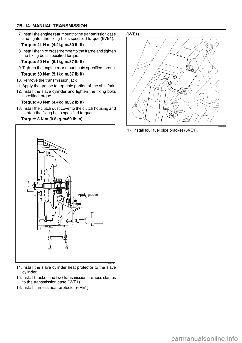
11. Apply the grease to top hole portion of the shift fork.
12. Install the slave cylinder and tighten the fixing bolts
specified torque.
Torque: 43 N´m (4.4kg´m/32 Ib ft)
13. Install the clutch dust cover to the clutch housing and
tighten the fixing bolts specified torque.
Torque: 8 N´m (0.8kg´m/69 Ib in)
220RS007
14. Install the slave cylinder heat protector to the slave
cylinder.
15. Install bracket and two transmission harness clamps
to the transmission case (6VE1).
16. Install harness heat protector (6VE1).(6VE1)
225RW006
17. Install four fuel pipe bracket (6VE1).
Page 2568 of 3573
LIGHTING SYSTEM8A–29
Light NameRated PowerNumber of
BulbsLens ColorRemarks
Headlight60w/55w2WhiteHalogen
FrontTurn signal light21w2Whitecombination
lightClearance light5w2Amber
FRT fog light55w2WhiteHalogen
Taillight/Stoplight5w/21w2Red
RearBumperTurn signal light21w2Ambercombination
lightTaillight/Stoplight5w/21w2RedBodyTurn signal light21w2Amber
Backup light21w2White
RR fog light21w2Red
Side turn signal light5w2Amber
License plate lightBumper5w2White
Body5W1White
High mount stoplight——RedLED
Map light5w2White
Dome light10w1White
Luggage room light8w1White
Courtesy light3.8w2White
A/C SW60mA1
RR defogger SW0.84w1
Mirror defogger SW0.84w1
FRT fog light SW0.7w1
RR fog light SW0.7w1
Cruise (Set)1.4w1Meter
Cruise (Main)1.4w1Meter
Check trans3w1Meter
Anti-theft3w1Warning box
Turn signal1.4w2Meter
Golw1.4w1Meter
Water sedimenter1.4w1Meter
Indicator/High beam1.4w1MeterWarning
lightABS1.4w1Meter
Check engine1.4w1Meter
Low fuel1.4w1Meter
4WD1.4w1Meter
Oil Pressure1.4w1Meter
Brake system1.4w1Meter
Charge1.4w1Meter
Seat belt2w1Meter
A/T shift position0.91w7Meter
A/T oil temp3w1Meter
Page 2604 of 3573
WIRING SYSTEM 8DÐ11
Abbreviation Meaning of Abbreviation
A
ABS
ASM
AC
A/C
ACC
A/T
C/B
CSD
DIS
EBCM
ECGI
ECM
ECU
EFE
EGR
4A/T
4WD
FL
FRT
H/L
IC
IGAmpere (S)
Anti-lock brake system
Assembly
Alternating current
Air conditioner
Accessories
Automatic transmission
Circuit breaker
Cold start device
Direct ignition system
Electronic brake control module
Electronic control gasoline injection
Engine control module
Electronic control unit
Early fuel evaporation
Exhaust gas recirculation
4-speed automatic transmission
Four-wheel drive
Fusible link
Front
Headlight
Integrated circuit
IgnitionAbbreviation Meaning of Abbreviation
kW
LH
LWB
M/T
OD
OPT
PCM
QOS
RH
RR
SDM
SRS
ST
STD
SW
SWB
3A/T
V
VSV
W
WOT
W/
W/OKilowatt
Left hand
Long wheel base
Manual transmission
Over drive
Option
Powertrain control module
Quick on start
Right hand
Rear
Sensing and diagnostic module
Supplemental restraint system
Start
Standard
Switch
Short wheel base
3-speed automatic transmission
Volt
Vacuum switching valve
Watt (S)
Wide open throttle
With
Without
Abbreviations
Page 2618 of 3573
WIRING SYSTEM 8DÐ25
Relay & Fuse Box
FL-1
FL-2 FL-6 FL-5 FL-4 FL-3
F-12 F-11 F-10 F-9 F-8 F-7 F-6 F-5 F-4 F-3 F-2 F-1 RELAY AND FUSE BOX
RHD
FUSIBLE LINK FUSE
MODEL
No.
FL-1
FL-2
FL-3
FL-4
FL-5
FL-6
F-1
F-2
F-3
F-4
F-5
F-6
F-7
F-8
F-9
F-10
F-11
F-12LHD
80A MAIN
50A KEY SW
30A ECM (GASOLINE)
30A CONDENSER FAN
50A GLOW (4JG2)
40A ABS
10A O
2 SENSOR (GASOLINE)
15A HORN HAZARD
15A H/LAMP-LH
15A H/LAMP-RH
15A ANTI-THEFT
20A FOG
20A ABS
15A FUEL PUMP (GASOLINE)
15A TAIL80A MAIN
50A KEY SW
30A ECM (GASOLINE)
30A CONDENSER FAN
50A GLOW (4JG2)
40A ABS
10A O2 SENSOR (GASOLINE)
15A HORN HAZARD
10A H/LAMP-LH (HI)
10A H/LAMP-RH (HI)
10A H/LAMP-LH (LOW)
10A H/LAMP-RH (LOW)
20A FOG
20A ABS
15A FUEL PUMP (GASOLINE)
10A TAIL-LH
10A TAIL-RH —
—
——
810RS027
Page 2619 of 3573
8DÐ26 WIRING SYSTEM
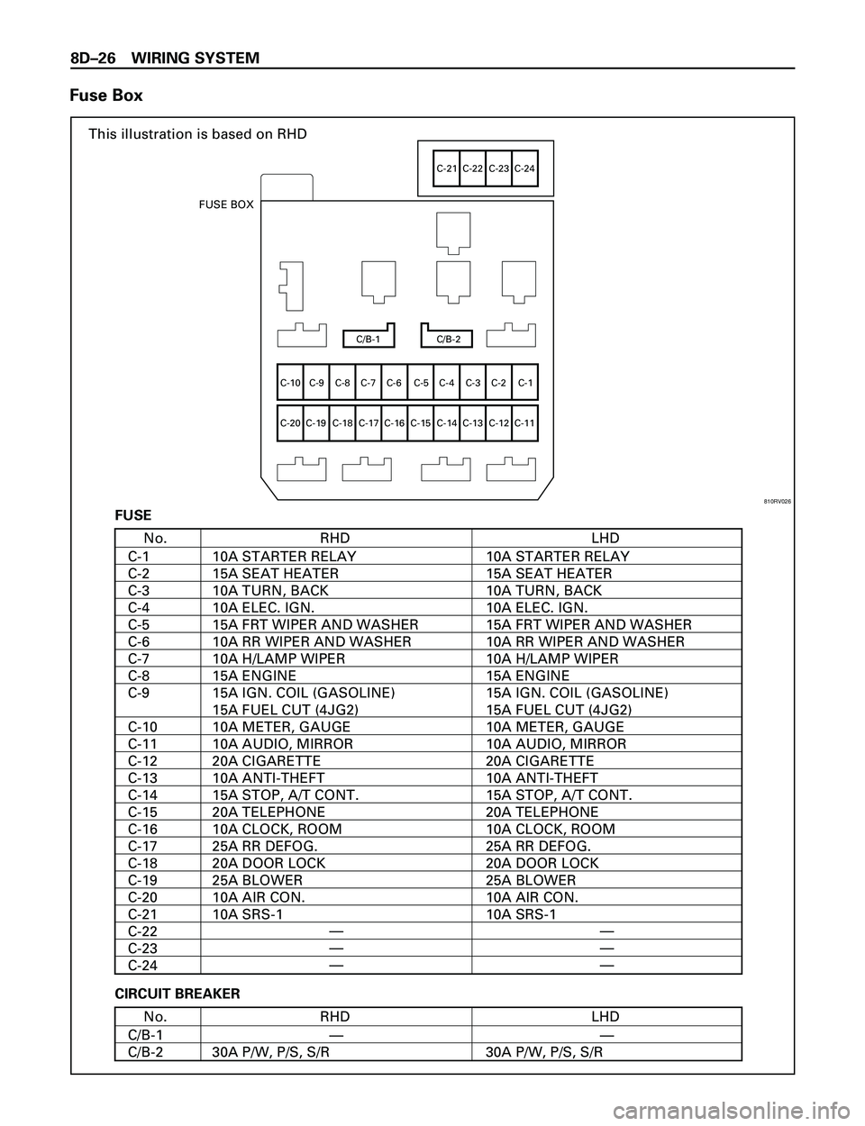
Fuse Box
This illustration is based on RHD
C/B-1 C/B-2
C-10
C-20C-9 C-8 C-7 C-6 C-5 C-4 C-3 C-2 C-1
C-19 C-18 C-17 C-16 C-15 C-14 C-13 C-12 C-11
C-21 C-22 C-23 C-24
FUSE BOX
RHDNo.
C-1
C-2
C-3
C-4
C-5
C-6
C-7
C-8
C-9
C-10
C-11
C-12
C-13
C-14
C-15
C-16
C-17
C-18
C-19
C-20
C-21
C-22
C-23
C-24LHD
10A STARTER RELAY
15A SEAT HEATER
10A TURN, BACK
10A ELEC. IGN.
15A FRT WIPER AND WASHER
10A RR WIPER AND WASHER
10A H/LAMP WIPER
15A ENGINE
15A IGN. COIL (GASOLINE)
15A FUEL CUT (4JG2)
10A METER, GAUGE
10A AUDIO, MIRROR
20A CIGARETTE
10A ANTI-THEFT
15A STOP, A/T CONT.
20A TELEPHONE
10A CLOCK, ROOM
25A RR DEFOG.
20A DOOR LOCK
25A BLOWER
10A AIR CON.
10A SRS-110A STARTER RELAY
15A SEAT HEATER
10A TURN, BACK
10A ELEC. IGN.
15A FRT WIPER AND WASHER
10A RR WIPER AND WASHER
10A H/LAMP WIPER
15A ENGINE
15A IGN. COIL (GASOLINE)
15A FUEL CUT (4JG2)
10A METER, GAUGE
10A AUDIO, MIRROR
20A CIGARETTE
10A ANTI-THEFT
15A STOP, A/T CONT.
20A TELEPHONE
10A CLOCK, ROOM
25A RR DEFOG.
20A DOOR LOCK
25A BLOWER
10A AIR CON.
10A SRS-1 FUSE
RHDNo.
C/B-1
C/B-2LHD
30A P/W, P/S, S/R 30A P/W, P/S, S/R—— CIRCUIT BREAKER
—
—
——
—
—
810RV026
Page 2620 of 3573
WIRING SYSTEM 8DÐ27
Relay Location-1 (Relay and Fuse Box)
RHDNo.
X-1
X-2
X-3
X-4
X-5
X-6
X-7
X-8
X-9
X-10
X-11
X-12
X-13
X-16
X-17
X-18
X-19
X-20
X-21
X-22
X-23LHD
RELAY ; LIGHTING
RELAY ; A/C THERMO
RELAY ; COMPRESSOR (GASOLINE)
RELAY ; HORN
RELAY ; TAIL
RELAY ; FUEL PUMP (GASOLINE)
RELAY ; ECM MAIN (GASOLINE)
RELAY ; ANTI-THEFT
RELAY ; STARTER (GASOLINE)
RELAY ; CHARGE (DIESEL)
RELAY ; SHIFT ON THE FLY
RELAY ; CONDENSER FAN
(GASOLINE)
RELAY ; RR FOG LIGHT
RELAY ; FRT FOG LIGHTRELAY ; LIGHTING
RELAY ; DIMMER
RELAY ; A/C THERMO
RELAY ; COMPRESSOR (GASOLINE)
RELAY ; HORN
RELAY ; TAIL
RELAY ; FUEL PUMP (GASOLINE)
RELAY ; ECM MAIN (GASOLINE)
RELAY ; ANTI-THEFT
RELAY ; STARTER (GASOLINE)
RELAY ; CHARGE (DIESEL)
RELAY ; SHIFT ON THE FLY
RELAY ; CONDENSER FAN
RELAY ; FRT FOG LIGHT
—
—
—
—
—
—
—
——
—
—
—
—
—
—
—
X-1
X-2
X-3
X-4X-5
X-6
X-7
X-8X-9
X-10 X-12X-11X-13X-16
X-17X-18
X-19X-20
X-21
X-22
X-23 RELAY AND FUSE BOX
810RS029


