Page 2998 of 3573

WIRING SYSTEM 8DÐ405
TERMINAL
CONNECTIONCHECK
OPERATIONCIRCUIT
NO. ITEM CONDITION
1 FRT door switchÐLH, RH ContinuityOpen door Continuity
Close door No continuity
2 RR door switchÐLH, RH ContinuityOpen door Continuity
Close door No continuity
3Ñ Ñ Ð Ð
4 Door lock key switchÐLH, RH Continuity Lock with key Continuity
5 FRT door lock switchÐLH, RH Continuity Lock Continuity
6 Tailgate switch ContinuityOpen tailgate Continuity
Close tailgate No continuity
8 AntiÐtheft horn Voltage Ð Approx. 12V
10 Battery Voltage Ð Approx. 12V
11 Door switch ContinuityUnlock with locking knob Continuity
Lock with locking knob No continuity
12 Engine hood switch ContinuityOpen engine hood Continuity
Close engine hood No continuity
13 Detect switch ContinuityUnlock with key Continuity
Lock with key No continuity
14 Door lock key switch Continuity Unlock Continuity
15 FRT door lock switchÐLH, RH Continuity Unlock Continuity
16 Tamper switch Continuity Ð No continuity
17 Ground Continuity Ð Continuity
18 Starter switch Voltage Starter switch ÒACCÓ Approx. 12V
19 Indicator light Voltage Ð Approx. 12V
20 Dome light Voltage Dome light ÒDOORÓ position Approx. 12V
21 Anti-theft relay Voltage Ð Approx. 12V
22 Starter relay VoltageMode switch ÒPÓ or ÒNÓ Approx. 12V
Clutch pedal depressed Approx. 12V
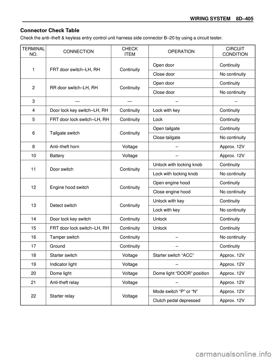
Connector Check Table
Check the antiÐtheft & keyless entry control unit harness side connector BÐ20 by using a circuit tester.
Page 3064 of 3573
WIRING SYSTEM 8D – 471
Heater and Air Conditioning
General Description
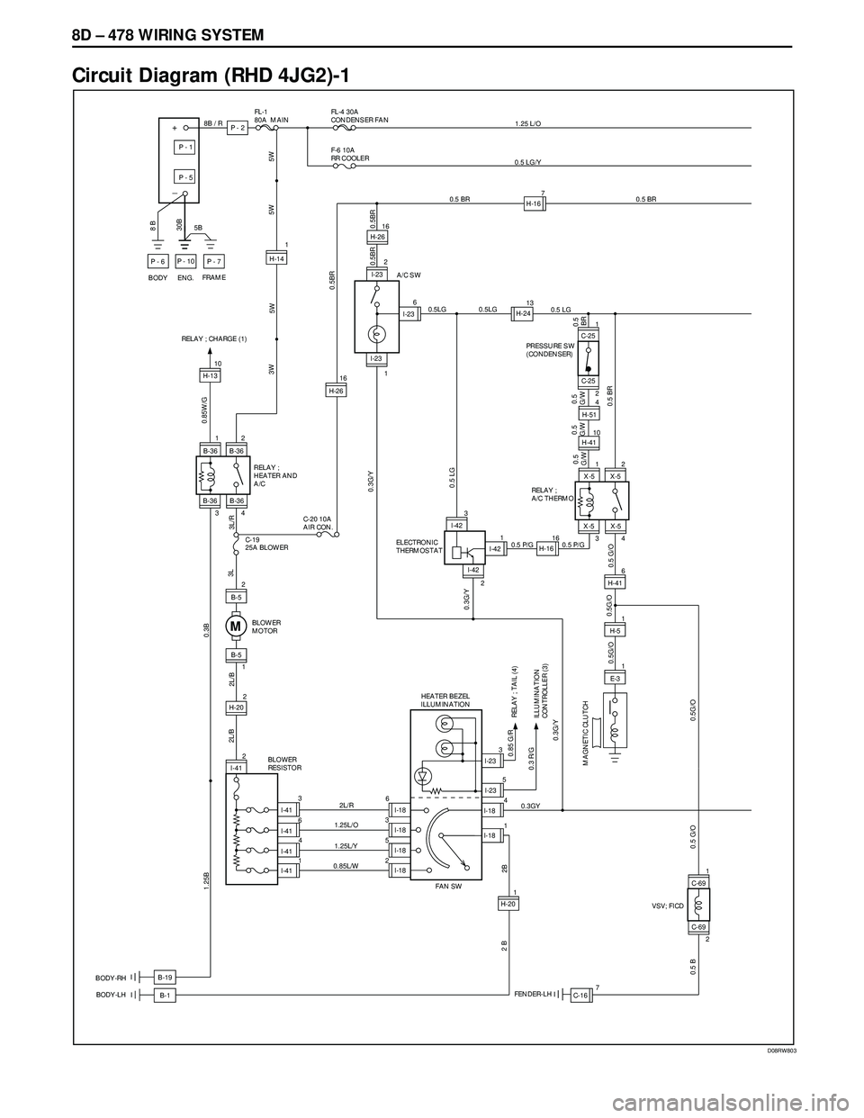
The circuit consists of pressure switch, A/C switch,
electronic thermostat, blower motor, fan switch,
magnetic clutch of A/C compressor, blower resistor
and relay.
The operation of A/C system is controlled by turning
A/C switch on and off. Electronic thermostat and PCM
can stop operation of A/C temporarily by disconnect-
ing magnetic clutch under the predetermined condi-
tions to adjust room temperature, preventing abnor-
mal rise of engine coolant and reduce engine load
while A/C is in operation.
Refer to Heating, Ventilation and Air Conditioning in
HVAC section.
Page 3066 of 3573
WIRING SYSTEM 8D – 473
Circuit Diagram (RHD 6VD1)-2
D08RW771
0.5 LG
X - 5 X - 5
X - 5 X - 5
14 RELAY ;
A/C THERMO320.5 P/G
0.3 G/Y
1.25 BX - 7 X - 7
X - 7 X - 7
43 21
H - 416H - 415
H - 49
E - 31
0.5BR/Y 0.5BR/Y
0.5G/B 0.5G/B 0.5BR/Y
0.5 BR
PCM (E15)
PCM (B14)0.5 G/O
0.5
G/W 0.5
G/W0.5
G/W
RELAY;
A/C COMPRESSOR MAGNETIC CLUTCH
0.5 LG
0.5 BR
C - 25 C - 25PRESSURE SW
(CONDENSER)
2H-4112
C - 39 FENDER-RH
1 1
H-51
6H-15
1
1
H-31
2
H-50 7
C-39
0.5 LG/Y 0.5 BR0.5 BR 0.5 BR
0.5 BR 0.5 LG
0.5B
0.5B 3 B 0.5LG/B0.5LG/B 0.5LG/B
R - 3
BODY-RR
X - 6 X - 6
X - 6
H-50
RR COOLER
CONNECTOR X - 6
RELAY ; RR COOLER
12
X-19X-19
53 34
C-253
TRIPLE SW
4
H-51
0.5 W/G3
H-42
0.5 W/G2
0.5 W/G4
X-191
X-19
C-75
1.25L
1
H - 163
0.3G/Y
M
2C-75
1.25B
(IF EQUIPPED)
RELAY; CONDENSER FAN CONDENSER FAN
1.25 L/O
C-25
H-417 4
H-512
Page 3069 of 3573
8D – 476 WIRING SYSTEM
D08RW699
Circuit Diagram (LHD 6VD1)-2
0.5BR/Y
5
0.5BR/Y
H - 415
H-15
1
1
H-31
2
H-50 7
C-39
X - 5 X - 5
X - 5 X - 5
34 RELAY ;
A/C THERMO12
H-416 0.5 P/G
0.5 BR 0.5 G/O
0.5 BR
0.5 LG/Y 0.5 BR
0.5 BR
0.5 BR
X - 7 X - 7
X - 7 X - 7
43 21
H - 417
H - 69
E - 31
0.5BR/Y
0.5G/B
0.5B
0.5B 3 B 0.5LG/B0.5LG/B 0.5LG/B
R - 3
BODY-RR
PCM (B14)
PCM (E15)
X - 6 X - 6
X - 6
H-50
RR COOLER
CONNECTOR X - 6
RELAY ; RR COOLER
12
RELAY;
A/C COMPRESSOR MAGNETIC CLUTCH
0.5G/W
0.5G/W
0.5G/W
H-51
0.5 BR
C - 25 C - 25DUAL PRESSURE SW
or
TRIPLE SW
2H-4112 1H-514
X-19X-19
53 34
C-253
TRIPLE SW
4
H-51
0.5 W/R3
H-42
0.5 W/R2
0.5 W/R4
X-191
X-19
C-75
1.25L
1
H - 1217
0.3G/Y
M
2C-75
1.25B
(IF EQUIPPED)
RELAY; CONDENSER FAN CONDENSER FAN
1.25 L/O
C-25
C-39 FENDER-RH2
0.3 G/Y
0.5 LG 0.5 LG2
Page 3071 of 3573

8D – 478 WIRING SYSTEM
Circuit Diagram (RHD 4JG2)-1
D08RW803
C-69
FENDER-LHB-1 BODY-RH
BODY-LH
FRAME
ENG.5B
BODY
8B / R
8 B
+
_
P - 6
30B
P - 1
P - 5
P - 10
P - 7
P - 2
FL-1
80A MAINFL-4 30A
CONDENSER FAN
F-6 10A
RR COOLER
1
2 I-232
I-23
I-236
1A/C SW
BLOWER
MOTOR
0.5G/O
I-42 I-42
I-421 3
216
0.5
G/W 0.5 LG
C-25
C-25
0.5LG
H-141
5W
B-190.5 BR
0.5BR 0.5BR
X-5 X-5
X-5 X-5
34 RELAY ;
A/C THERMO1
2
0.5 P/G 0.5 P/G
H-41100.5
G/W0.5
G/W
0.5 BR0.5
BR
PRESSURE SW
(CONDENSER) H-2413
0.5 LG
H-16 0.5LG
0.3GY
H-416
H-51
E-31
0.5 G/O
2L/R
I-41
I-18
I-18
I-18
I-18 1.25L/O
1.25L/Y
0.85L/W 3
36
5
2 4
1 6
FAN SW HEATER BEZEL
ILLUMINATION
I-23 I-23
I-18
I-18 3
5
4
10.3 R/G0.85 G/R
ILLUMINATION
CONTROLLER (3)RELAY ; TAIL (4)
H-201 2
BLOWER
RESISTOR
I-41
I-41
I-41
I-41
2L/B
2 B
1.25B
M
B-52
1B-5
B-361
B-36
B-36 B-362
34
3L/R 3LC-19
25A BLOWERRELAY ;
HEATER AND
A/C
0.3B
ELECTRONIC
THERMOSTAT
MAGNETIC CLUTCH
0.5G/O
5W 3W
0.5 BR 1.25 L/O
0.5 LG/Y
2B
C-20 10A
AIR CON.
0.5BR
7H-16
0.3G/Y
0.3G/Y0.3G/Y5W
0.85W/G
RELAY ; CHARGE (1)
H-1310
2
H-202L/B
VSV; FICD
C-69
2 1
0.5G/O 0.5 G/O
C-167
0.5 B
H-2616
H-2616
H-514
Page 3075 of 3573
8D – 482 WIRING SYSTEM
Circuit Diagram (LHD 4JG2)-2
D08RW826
5H-15
1
1
H-31
2
H-50 7
C-39
X - 5 X - 5
X - 5 X - 5
34 RELAY ;
A/C THERMO12
H-416 0.5 P/G
0.5 BR 0.5 G/O 0.5 G/O
0.5 G/O
0.5 G/O
0.5 LG/Y 0.5 BR
H - 51
E - 3
C-16 1
0.5B
0.5B 3 B 0.5LG/B0.5LG/B 0.5LG/B
R - 3
BODY-RR
X - 6 X - 6
X - 6
H-50
RR COOLER
CONNECTOR X - 6
RELAY ; RR COOLER
12
MAGNET CLUTCH
0.5G/W
0.5G/W
0.5G/W
H-51
0.5 BR
C - 25 C - 25DUAL PRESSURE SW
or
TRIPLE SW
2H-4110 1H-514
X-19X-19
53 3
7
0.5B
C-69
C-69
VSV;FICD
1
24
C-25
3
TRIPLE SW
4
H-51
0.5 W/R3
H-42
0.5 W/R2
0.5 W/R4
X-191
X-19
C-75
1.25L
1
H - 1217
0.3G/Y
M
2C-75
1.25B
(IF EQUIPPED)
RELAY; CONDENSER FAN CONDENSER FAN
1.25 L/O
C-25
C-39 FENDER-RH2
0.3 G/Y
0.5 LG 0.5 LG2
Page 3133 of 3573
8D – 540 WIRING SYSTEM
Circuit Diagram (RHD 6VE1)-2
D08RW611
FRT AXLE
SWT.O.D. CONTROL UNIT3
C-16
FENDER-LHM-220.5
L/Y
0.5
G0.5
G/W0.5
G/R0.5
G/Y
0.5
LB
0.5
G/R0.5
G
0.5
G0.5
G 0.5
G/W0.5
G/R0.5
G/R0.5
G/Y0.5
LB 0.5
L/Y
0.5
L/Y 0.5
BR/R
0.5
P
0.5
Y
0.5
Y
0.5
B0.5
B
0.5
B
0.85
B0.5
L/Y
2M-225H-10
122B-68
5H-1210H-102
M-231M-233H-10B-67
5H-72
FRT SPEED
SENSOR
(TRANSFER)RR SPEED
SENSOR
(TRANSFER)CLUTCH
SOLENOID
(TRANSFER)
M-241M-24
2
A-33H-49B-67
7
6
A-314H-49B-68
12
10
A-313H-492
H-497
H-49
B-67
10
5
A-3 9
A-31
A-3 12
H-49B-68
11
8
A-3H-49B-67
4
4
VSV;
FRT AXLE(C)VSV;
FRT AXLE(D)
Page 3361 of 3573

8H±22SECURITY AND LOCKS
Anti-theft System
General Description
The circuit consists of the starter switch, anti-theft &
keyless entry control unit, anti-theft horn, front door and
tailgate key switch (detect and tamper switch), door lock
(& power window) switch, door lock actuator for each
door, engine hood switch, clutch start switch (M/T),
ANTI-THEFT indicator light and mode switch (A/T).
The system operates as follows: After locking the starter
switch and removing the starter key (this sets the alarm),
if the door is unlocked in any way other than with the
proper key, the headlights start flashing, the horn sounds,
and the starter circuit is disabled. (However, the engine
hood and all the doors must be locked and closed.)
Once the system has been placed in the warning or alarm
condition, it can be released only when the starter switch
is shifted from ªOFFº to ªACCº by the starter key, or when
the lock of the front door or the tailgate is released (to
activate the detect switch) by the starter key.
Anti-theft & Keyless Entry Control
Unit Removal
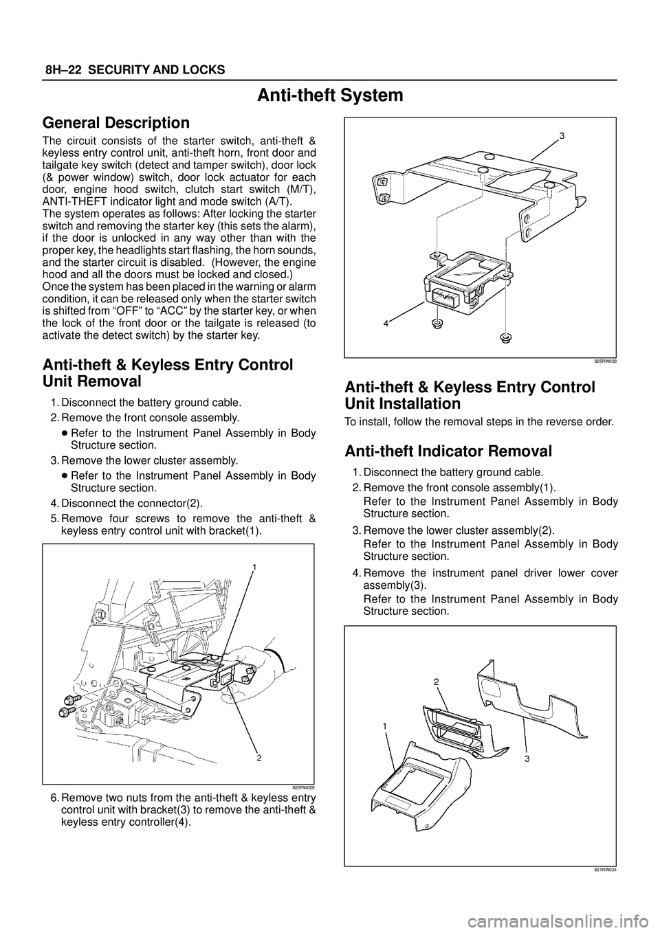
1. Disconnect the battery ground cable.
2. Remove the front console assembly.
�Refer to the Instrument Panel Assembly in Body
Structure section.
3. Remove the lower cluster assembly.
�Refer to the Instrument Panel Assembly in Body
Structure section.
4. Disconnect the connector(2).
5. Remove four screws to remove the anti-theft &
keyless entry control unit with bracket(1).
825RW029
6. Remove two nuts from the anti-theft & keyless entry
control unit with bracket(3) to remove the anti-theft &
keyless entry controller(4).
825RW028
Anti-theft & Keyless Entry Control
Unit Installation
To install, follow the removal steps in the reverse order.
Anti-theft Indicator Removal
1. Disconnect the battery ground cable.
2. Remove the front console assembly(1).
Refer to the Instrument Panel Assembly in Body
Structure section.
3. Remove the lower cluster assembly(2).
Refer to the Instrument Panel Assembly in Body
Structure section.
4. Remove the instrument panel driver lower cover
assembly(3).
Refer to the Instrument Panel Assembly in Body
Structure section.
821RW024