Page 2539 of 3573
7C±30CLUTCH
Special Tools
ILLUSTRATIONTOOL NO.
TOOL NAME
5-85253-001-0
(J-24547)
Driven plate aligner
5-8840-2000-0 and
5-8840-0019-0
(J-5822 and J-23907)
Pilot bearing remover
and Sliding hammer
5-8840-0125-0
(J-26516-A)
Crankshaft pilot bearing
installer
5-8840-0007-0
(J-8092)
Driver handle
Page 2651 of 3573
8DÐ58 WIRING SYSTEM
Circuit Diagram (6V
*1) Ð 4
D
H
G
3.0
W
3.0
L/R 3.0
L/B
0.5
O/G
AUDIO
CIGARETTE
LIGHTERBLOWER
MOTORMAGNETIC
CLUTCHPOWER
WINDOW
RELAY
(2)STOPLIGHT AUDIO
(14)
DOME LIGHTRR DEFOGGER
FRT DOOR LOCK &
POWER WINDOW SW C-11 10A
AUDIO
(ACC)
MIRROR
0.5
BRC-20 10A
AIR CON
0.85
G/WC-14 15A
STOP
A/T CONT
1.25
R/WC-15 20A
AUDIO (B)
3.0
L/OC-17 25A
RR
DEFOG
FUSE BOX
1.25
O/BC-12 20A
CIGAR
3.0
LC-19 25A
BLOWER
3.0
B/L 3.0
W5.0
W 5.0
W
5.0
W
C/B-2 30A
P/W,P/S,
S/R
0.5
R/WC-16 10A
CLOCK (B)
ROOM
1.25
LG/WC-18 20A
DOOR
LOCK
HEATER &
A/C RELAY
B-36
2
B-364
D08RWB16
Page 2659 of 3573
8DÐ66 WIRING SYSTEM
Circuit Diagram (Diesel) Ð 5
D
K
J
3.0
W
3.0
L/R 3.0
L/B
0.5
O/G
AUDIO CIGARETTE
LIGHTERBLOWER
MOTORMAGNETIC
CLUTCHPOWER
WINDOW
RELAY
(2)STOPLIGHT AUDIO
(14)
DOME LIGHT FRT DOOR LOCK &
POWER WINDOW SW RR DEFOGGER C-11 10A
AUDIO
(ACC)
MIRROR
0.5
BRC-20 10A
AIR CON
0.85
G/WC-14 15A
STOP
A/T CONT
1.25
R/WC-15 20A
AUDIO (B)
3.0
L/OC-17 25A
RR
DEFOG
FUSE BOX
1.25
O/BC-12 20A
CIGAR
3.0
LC-19 25A
BLOWER
3.0
B/L 3.0
W5.0
W 5.0
W
5.0
W
C/B-2 30A
P/W,P/S,
S/R
0.5
R/WC-16 10A
CLOCK (B)
ROOM
1.25
LG/WC-18 20A
DOOR
LOCK
HEATER &
A/C RELAY
B-36
2
B-364
D08RWB21
Page 2865 of 3573

8DÐ272 WIRING SYSTEM
General Description
The circuit consists of cruise control unit, cruise
main switch, combination switch, clutch switch
(M/T), mode switch (A/T), brake switch, actuator and
indicator lights.
Cruise control system keeps the vehicle running at a
fixed speed until a signal canceling this fixed speed
is received.
When the cruise main switch is turned on with the
vehicle in the running mode, the battery voltage is
applied to the control unit.
When a signal from the combination switch is input
to the control unit while vehicle is in this state, the
actuator is activated to operate the system. Also,
while the system is operating, the cruise indicator
light in the meter panel lights up.
Set Function
When the cruise main switch turned on and the set
switch is depressed with the vehicle speed within
the set limit and cancel operation is refused, the
vehicle speed when the set switch is released is
stored in the control unit as the set speed. But in
case of the vehicle speed is over maximum limit
speed of cruise control, maximum limit speed in the
control unit is stored as the set speed.
Resume Function
Unless the vehicle speed falls below the minimum
speed limit after canceling the set speed by the
cancel switch, pushing the resume switch causes
the vehicle to resume the speed before cancellation.
Acceleration Function
During cruise control driving, pushing the
acceleration switch (on time is more than 0.6 sec.)
causes an increase in cruise speed and vehicle
accelerates at a controlled rate untill acceleration
switch released.
Vehicle speed at the acceleration switch released
plus 1.0 km/h is stored in the control unit as the set
speed.
Tap up Function
During cruise control driving, pushing the coast
switch (on time is more than 0.6 sec.) causes a
decrease in cruise speed and the vehicle decelerate
at a controlled rate until coast switch released.
Vehicle speed at the coast switch released minus
approx. 1.0 km/h is stored in the control unit as the
set speed.
Tap down Function
During cruise control driving, the set speed can be
lowered approx. 1.0 km/h each time by operating
the coast switch quickly within 0.6 sec.
Cancel Function
During cruise control driving, the cruise control is
released if the control unit receives a signal from the
cancel switch, mode switch, clutch switch or brake
switch. The set speed is still stored.
Down Cancel Function
The cruise control is canceled when the vehicle
speed becomes the set speed minus 20 km/h during
the cruise control working and the set speed is
erased.
Over Drive (OD) Cancel Function
OD cancel function is required when the vehicle
speed becomes the set speed minus 3 km/h during
the cruise control working.
OD cancel function is enabled when the acceleration
function and/or resume function are working except
the vehicle speed is in more than 120 km/h.
Cruise Control
Page 2866 of 3573
WIRING SYSTEM 8DÐ273
Circuit Diagram (RHD)-1
5
I-6
11
12
H-26
0.5
L/W0.5
L/W0.5
L/W0.5
R/B
0.85
R/B
0.75
R/B
0.5
L/B
0.5
L/B
0.5
L/B
0.5
L/B(A/T)
0.5
L/B 0.5
LG0.5
BR/Y0.5
GR/G
0.5
B
2.0
B 3.0
B/Y
0.85
L/W
0.5
L/W
0.5
P/B0.3
R/G 0.85
L/W0.5
L/W
0.85
G/R
0.5
P/B C-4 15A
ELEC.IGN.C-3 10A
TURN,BACK
CRUISE
MAIN
SWCLUTCH
SW
(M/T)MODE
SW COMBINATION
SW
CRUISE CONTROL UNIT
STARTER SW
(IG1)
BODY-LH 20
H-25
4
I-6
1
B-9
TAIL RELAY
(4)
ILLUMINATION
CONTROLLER(3)
PCM
(F2)
2
I-6
1
B-16 6
I-6
B-529
B-5212
10
B-52
11
B-52
13
B-52
4
B-93
B-910
B-912
B-9
B-1
2
B-16
16
B-9 B-9
M-25H-53H-7
12B-93 3 7H-88M-256H-1117
SET
RESUME
CANCEL
D08RW661
Page 2869 of 3573
8DÐ276 WIRING SYSTEM
Circuit Diagram (LHD)-1
5
I-6
11
6
H-48
0.5
L/W0.5
L/W0.5
L/W0.85
R/B
0.85
R/B
0.75
R/B
0.5
L/B
0.5
L/B
0.5
L/B
0.5
L/B(A/T)
0.5
L/B 0.5
LG0.5
BR/Y0.5
GR/G
0.5
B
2.0
B 3.0
B/Y
0.5
L/W
0.5
L/W
0.5
P/B0.3
R/G 0.85
L/W 0.85
L/W
0.85
G/R
0.5
P/B C-4 10A
ELEC.IGN.C-3 10A
TURN,BACK
CRUISE
MAIN
SWCLUTCH
SW
(M/T)MODE
SW COMBINATION
SW
CRUISE CONTROL UNIT
STARTER SW
(IG1)
BODY-RH 5
H-25
4
I-6
1
B-9
TAIL RELAY
(4)
ILLUMINATION
CONTROLLER(3)
PCM
(F2)
2
I-6
1
B-16 6
I-6
B-529
B-5212
10
B-52
11
B-52
13
B-52
4
B-93
B-910
B-912
B-9
B-2
2
B-16
16
B-9 B-9
M-25H-53H-8
12B-92 3 7H-88M-256H-114
SET
RESUME
CANCEL
D08RW957
Page 2872 of 3573

WIRING SYSTEM 8DÐ279
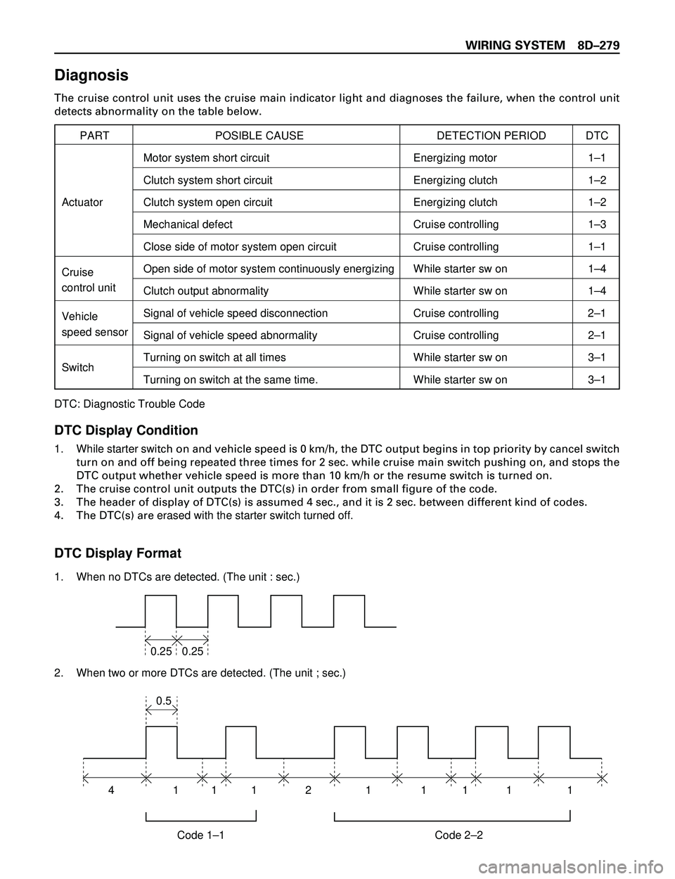
Diagnosis
The cruise control unit uses the cruise main indicator light and diagnoses the failure, when the control unit
detects abnormality on the table below.
PART POSIBLE CAUSE DETECTION PERIOD DTC
Motor system short circuit Energizing motor 1Ð1
Clutch system short circuit Energizing clutch 1Ð2
Actuator Clutch system open circuit Energizing clutch 1Ð2
Mechanical defect Cruise controlling 1Ð3
Close side of motor system open circuit Cruise controlling 1Ð1
CruiseOpen side of motor system continuously energizing While starter sw on 1Ð4
control unit
Clutch output abnormality While starter sw on 1Ð4
VehicleSignal of vehicle speed disconnection Cruise controlling 2Ð1
speed sensor
Signal of vehicle speed abnormality Cruise controlling 2Ð1
SwitchTurning on switch at all times While starter sw on 3Ð1
Turning on switch at the same time. While starter sw on 3Ð1
DTC: Diagnostic Trouble Code
DTC Display Condition
1. While starter switch on and vehicle speed is 0 km/h, the DTC output begins in top priority by cancel switch
turn on and off being repeated three times for 2 sec. while cruise main switch pushing on, and stops the
DTC output whether vehicle speed is more than 10 km/h or the resume switch is turned on.
2. The cruise control unit outputs the DTC(s) in order from small figure of the code.
3. The header of display of DTC(s) is assumed 4 sec., and it is 2 sec. between different kind of codes.
4. The DTC(s) are erased with the starter switch turned off.
DTC Display Format
1. When no DTCs are detected. (The unit : sec.)
2. When two or more DTCs are detected. (The unit ; sec.)
0.25 0.25
Code 1–1 Code 2–2 410.5
11 1 1 1 1 12
Page 2874 of 3573

WIRING SYSTEM 8DÐ281
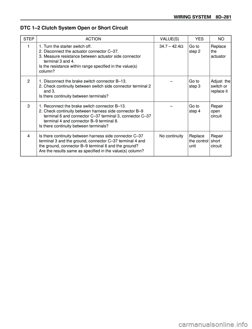
DTC 1Ð2 Clutch System Open or Short Circuit
STEP ACTION VALUE(S) YES NO
1. Turn the starter switch off.
2. Disconnect the actuator connector CÐ37.
3. Measure resistance between actuator side connector
terminal 3 and 4.
Is the resistance within range specified in the value(s)
column?
1. Disconnect the brake switch connector BÐ13.
2. Check continuity between switch side connector terminal 2
and 3.
Is there continuity between terminals?
1. Reconnect the brake switch connector BÐ13.
2. Check continuity between harness side connector BÐ9
terminal 6 and connector CÐ37 terminal 3, connector CÐ37
terminal 4 and connector BÐ9 terminal 8.
Is there continuity between terminals?
Is there continuity between harness side connector CÐ37
terminal 3 and the ground, connector CÐ37 terminal 4 and
the ground, connector BÐ9 terminal 6 and the ground?
Are the results same as specified in the value(s) column?34.7 Ð 42.4½
Ð
Ð
No continuityGo to
step 2
Go to
step 3
Go to
step 4
Replace
the control
unitReplace
the
actuator
Adjust the
switch or
replace it
Repair
open
circuit
Repair
short
circuit 1
2
3
4