Page 375 of 3573
SUPPLEMENTAL RESTRAINT SYSTEM STEERING WHEEL & COLUMN 2A Ð 73
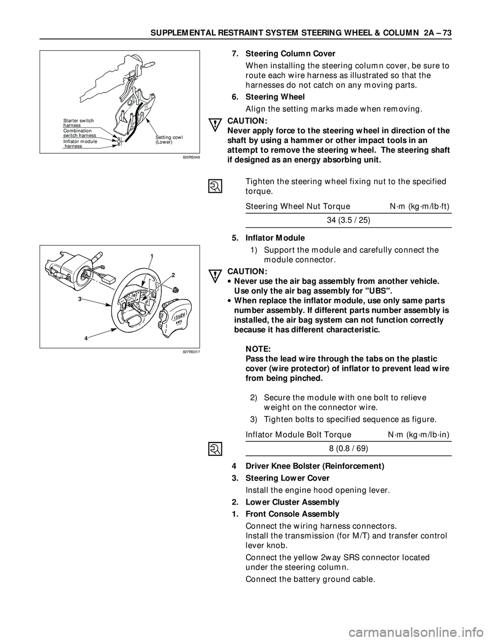
Starter switch
harness
Combination
switch harness
Inflator module
harness
Setting cowl
(Lower)
7. Steering Column Cover
When installing the steering column cover, be sure to
route each wire harness as illustrated so that the
harnesses do not catch on any moving parts.
6. Steering Wheel
Align the setting marks made when removing.
CAUTION:
Never apply force to the steering wheel in direction of the
shaft by using a hammer or other impact tools in an
attempt to remove the steering wheel. The steering shaft
if designed as an energy absorbing unit.
Tighten the steering wheel fixing nut to the specified
torque.
Steering Wheel Nut Torque Nám (kgám/lbáft)
34 (3.5 / 25)
5. Inflator Module
1) Support the module and carefully connect the
module connector.
CAUTION:
·Never use the air bag assembly from another vehicle.
Use only the air bag assembly for "UBS".
·When replace the inflator module, use only same parts
number assembly. If different parts number assembly is
installed, the air bag system can not function correctly
because it has different characteristic.
NOTE:
Pass the lead wire through the tabs on the plastic
cover (wire protector) of inflator to prevent lead wire
from being pinched.
2) Secure the module with one bolt to relieve
weight on the connector wire.
3) Tighten bolts to specified sequence as figure.
Inflator Module Bolt Torque Nám (kgám/lbáin)
8 (0.8 / 69)
4 Driver Knee Bolster (Reinforcement)
3. Steering Lower Cover
Install the engine hood opening lever.
2. Lower Cluster Assembly
1. Front Console Assembly
Connect the wiring harness connectors.
Install the transmission (for M/T) and transfer control
lever knob.
Connect the yellow 2way SRS connector located
under the steering column.
Connect the battery ground cable.
825RS048
3
41
2
827RS017
Page 378 of 3573
2A – 76 SUPPLEMENTAL RESTRAINT SYSTEM STEERING WHEEL & COLUMN
GENERAL DESCRIPTION
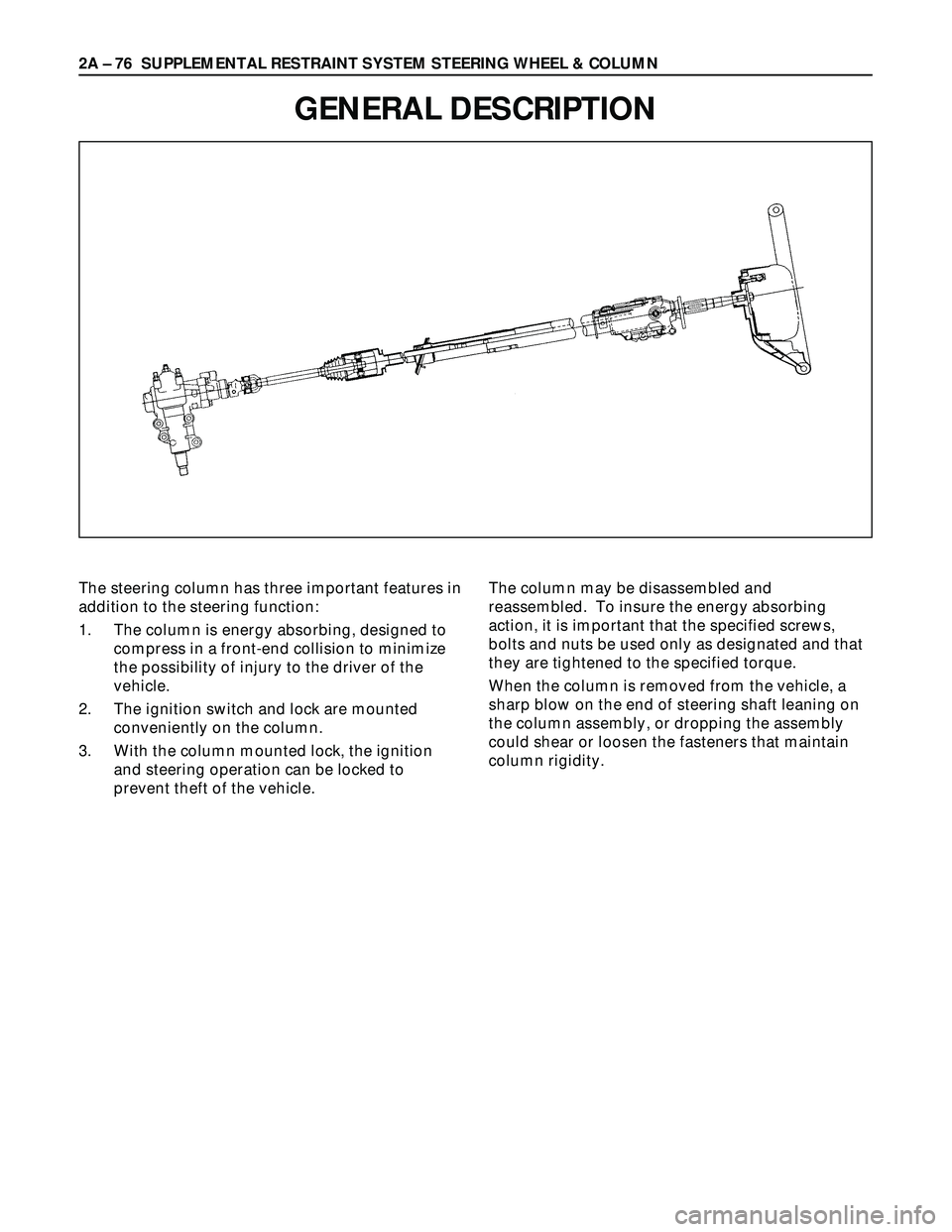
The steering column has three important features in
addition to the steering function:
1. The column is energy absorbing, designed to
compress in a front-end collision to minimize
the possibility of injury to the driver of the
vehicle.
2. The ignition switch and lock are mounted
conveniently on the column.
3. With the column mounted lock, the ignition
and steering operation can be locked to
prevent theft of the vehicle.The column may be disassembled and
reassembled. To insure the energy absorbing
action, it is important that the specified screws,
bolts and nuts be used only as designated and that
they are tightened to the specified torque.
When the column is removed from the vehicle, a
sharp blow on the end of steering shaft leaning on
the column assembly, or dropping the assembly
could shear or loosen the fasteners that maintain
column rigidity.
Page 380 of 3573
2A – 78 SUPPLEMENTAL RESTRAINT SYSTEM STEERING WHEEL & COLUMN
INSTALLATION
3. Steering Wheel
Align the setting marks made when removing.
CAUTION:
Never apply force to the setting wheel in direction of the
shaft by using a hammer or other impact tools in an
attempt to install the steering wheel. The steering shaft is
designed as an energy absorbing unit.
2. Nut
Steering Wheel Nut Torque N·m (kg·m/lb·ft)
34 (3.5 / 25)
1. Center pad
Fit four projections of pad in holes on the steering
wheel side.
Tighten the screws on the lower side of the pad.
Center Pad Nut Torque N·m (kg·m/lb·in)
2.5 (0.25 / 21.7) 3. Steering Wheel
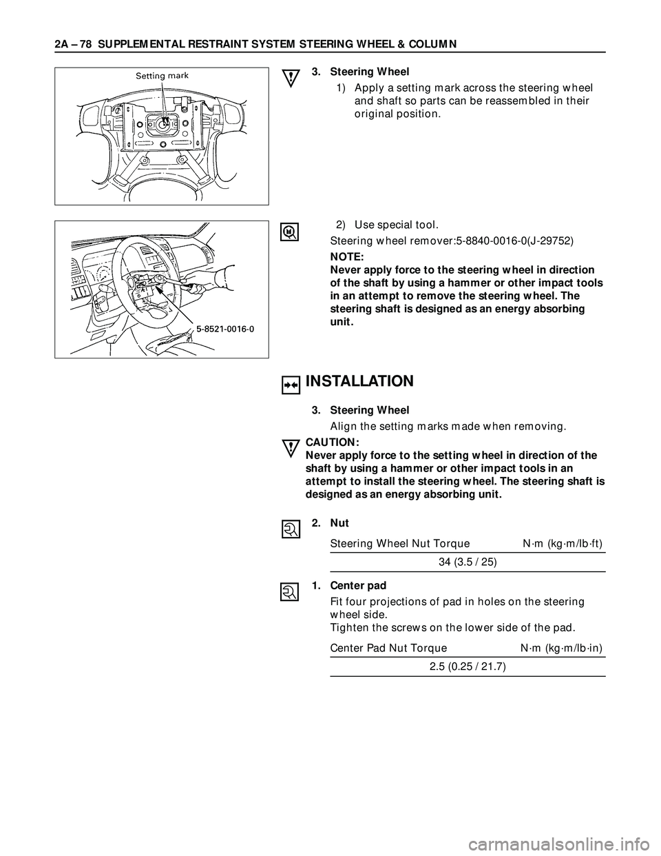
1) Apply a setting mark across the steering wheel
and shaft so parts can be reassembled in their
original position.
2) Use special tool.
Steering wheel remover:5-8840-0016-0(J-29752)
NOTE:
Never apply force to the steering wheel in direction
of the shaft by using a hammer or other impact tools
in an attempt to remove the steering wheel. The
steering shaft is designed as an energy absorbing
unit.
Page 382 of 3573

2A – 80 SUPPLEMENTAL RESTRAINT SYSTEM STEERING WHEEL & COLUMN
INSTALLATION
6. Combination switch
After installations of combinations switch assembly,
connect the combination switch wiring harness
connector.
5. Steering column cover
4. Steering wheel
Align the setting marks made when removing.
CAUTION:
Never apply force to the setting wheel in direction of the
shaft by using a hammer or other impact tools in an
attempt to remove the steering wheel. The steering shaft
is designed as an energy absorbing unit.
Tighten the steering wheel fixing nut to the specified
torque.
Steering wheel Nut Torque N·m (kg·m/lb·ft)
34 (3.5 / 25)
3. Steering lower cover
Install the engine hood opening lever.
2. Lower cluster assembly
1. Front console assembly
Install the transmission (for M/T) and transfer control
lever knob.
Install the wiring harness connectors. Use special tool. Remove the steering wheel.
Move the tires to the straight ahead positions before
removing the steering wheel.
Steering wheel remover:5-8840-0016-0(J-29752)
CAUTION:
Never apply force to the steering wheel in direction of the
shaft by using a hammer or other impact tools in an
attempt to remove the steering wheel. The steering shaft
is designed as an energy absorbing unit.
5. Steering column cover
6. Combination switch
Disconnect the wiring harness connector.
Page 385 of 3573
SUPPLEMENTAL RESTRAINT SYSTEM STEERING WHEEL & COLUMN 2A – 83
Tighten the steering wheel fixing nut to the specified
torque.
Steering wheel Nut Torque N·m (kg·m/lb·ft)
34 (3.5 / 25)
3. Steering lower cover
Install the engine hood opening lever.
2. Lower cluster assembly
1. Front console assembly
Connect the wiring harness connectors.
Install the transmission (for M/T) and transfer control
lever knob.
Page 388 of 3573
2A – 86 SUPPLEMENTAL RESTRAINT SYSTEM STEERING WHEEL & COLUMN
INSTALLATION
11. Steering column assembly
Align the setting marks on the universal joint and
steering shaft made during removal.
Tighten the steering column fixing bolt (dash panel)
to the specified torque.
Steering Column Bolt Torque N·m (kg·m/lb·ft)
19 (1.9 / 14)
Tighten the steering column fixing bolt ( pedal
bracket) to the specified torque.
Steering Column Bolt Torque N·m (kg·m/lb·ft)
17 (1.7 / 13)
Tighten the universal joint to the specified torque.
Universal Joint Torque N·m (kg·m/lb·ft)
25 (2.5 / 18)
10. Lock cylinder assembly
9. Shift lock cable (for A/T)
8. Cushion rubber
7. Snap ring
6. Combination switch
After installation of combination switch assembly,
connect the combination switch wiring harness
connector.
5. Steering column cover
4. Steering wheel
Align the setting marks made when removing.
CAUTION:
Never apply force to the steering wheel in direction of the
shaft by using a hammer or other impact tools in an
attempt to remove the steering wheel. The steering shaft
is designed as an energy absorbing unit.
Tighten the steering wheel fixing nut to the specified
torque.
Steering wheel Nut Torque N·m (kg·m/lb·ft)
34 (3.5 / 25)
3. Steering lower cover
Install the engine hood opening lever.
2. Lower cluster assembly
1. Front console assembly
Connect the wiring harness connectors.
Install the transmission (for M/T) and transfer control
Page 401 of 3573
FRONT SUSPENSION 3C – 13
4. Lower Ball Joint
Tighten the nut to the specified torque, with just
enough additional torque to align cotter pin holes.
Install new cotter pin.
Lower Ball Joint Nut Torque N·m (kg·m/lb·ft)
147 (15.0 / 108)
3. Back Plate
2. Wheel Speed Sensor (if equipped with ABS)
Tighten the bolt to the specified torque.
Wheel Speed Sensor Bolt Torque N·m (kg·m/lb·in)
8 (0.8 / 69)
1. Torsion Bar
Refer to “Torsion Bar” in this section.
NOTE:
Adjust the trim height. Refer to “Front End
Alignment” in section 2A.
Page 434 of 3573
WHEELS AND TIRES 3E – 3
ON-VEHICLE SERVICE
WHEELS
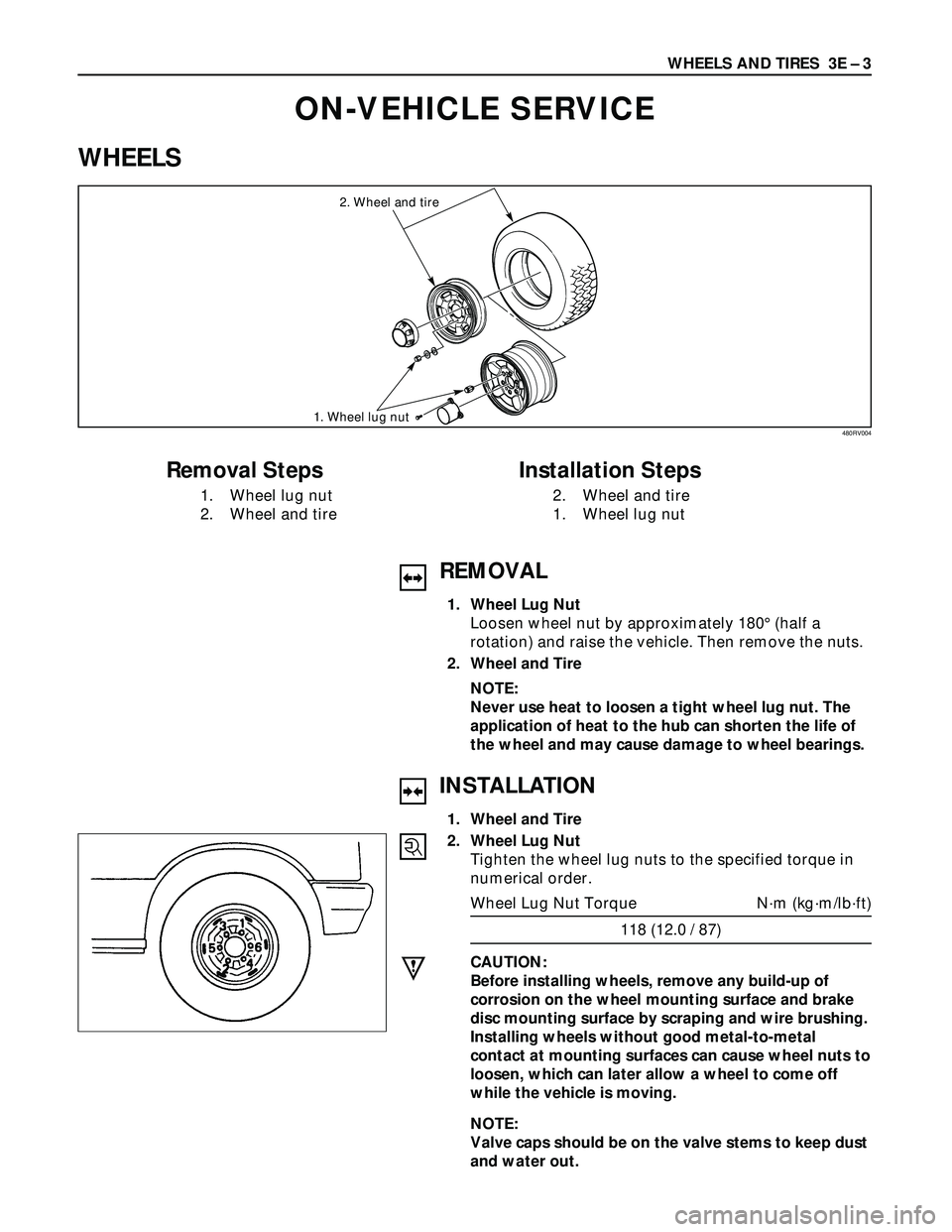
2. Wheel and tire
1. Wheel lug nut
Removal Steps
1. Wheel lug nut
2. Wheel and tire
Installation Steps
2. Wheel and tire
1. Wheel lug nut
480RV004
REMOVAL
1. Wheel Lug Nut
Loosen wheel nut by approximately 180° (half a
rotation) and raise the vehicle. Then remove the nuts.
2. Wheel and Tire
NOTE:
Never use heat to loosen a tight wheel lug nut. The
application of heat to the hub can shorten the life of
the wheel and may cause damage to wheel bearings.
INSTALLATION
1. Wheel and Tire
2. Wheel Lug Nut
Tighten the wheel lug nuts to the specified torque in
numerical order.
Wheel Lug Nut Torque N·m (kg·m/lb·ft)
118 (12.0 / 87)
CAUTION:
Before installing wheels, remove any build-up of
corrosion on the wheel mounting surface and brake
disc mounting surface by scraping and wire brushing.
Installing wheels without good metal-to-metal
contact at mounting surfaces can cause wheel nuts to
loosen, which can later allow a wheel to come off
while the vehicle is moving.
NOTE:
Valve caps should be on the valve stems to keep dust
and water out.