Page 311 of 3573

POWER STEERING 2A – 9
The hydraulic power steering system consists of a
pump, an oil reservoir, a steering gear, a pressure
hose and a return hose.
POWER STEERING GEAR
The power steering gear has a recirculating ball
system which acts as a rolling thread between the
worm shaft and the rack piston. When the worm
shaft is turned right, the rack piston moves up in
gear. Turning the worm shaft left moves the rack
piston down in gear. The rack piston teeth mesh
with the sector, which is part of the sector shaft.
Turning the worm shaft turns the sector shaft,
which turns the wheels through the steering
linkage.
The control valve in the steering gear directs the
power steering fluid to either side of the rack
piston. The rack piston converts the hydraulic
pressure into a mechanical force. If the steering
system becomes damaged and loses hydraulic
pressure, the vehicle can be controlled manually.
HYDRAULIC PUMP
The hydraulic pump is vane-type design.
There are two bore openings at the rear of the
pump housing. The smaller opening contains the
pressure line union and flow control valve.
PRESSURE SWITCH (6VD1,
6VE1 Engine)
When hydraulic pressure reaches 3650 ± 350 kPa
(530 ± 50 PSI), the pressure switch closes causing
ECM to actuate the idle air control valve to prevent
the overload-induced engine speed down. The
switch opens when hydraulic pressure drops to
3150 ± 350 kPa (460 ± 50PSI).
Page 312 of 3573

2A – 10 POWER STEERING
POWER STEERING SYSTEM TEST
TEST PROCEDURE
Test of fluid pressure in the power steering system
is performed to determine whether or not the oil
pump and power steering unit are functioning
normally.
The power steering system test is method used to
identify and isolate hydraulic circuit difficulties.
Prior to performing this test, the following
inspections and corrections, if necessary, must be
made.
INSPECT
•Pump reservoir for proper fluid level.
•Pump belt for proper tension.
•Pump driver pulley condition.
1. Place a container under the pump to catch the
fluid when disconnecting or connecting the
hoses.
2. With the engine NOT running , disconnect the
pressure hose at the power steering pump and
install Power Steering tester.
The gage must be between the shutoff valve
and pump. Open the shutoff valve.
Tester: 5-8840-0135-0 (J-29877-A)
Adapter: 5-8840-2297-0 (For 6VD1, 6VE1, 4JX1)
5-8840-0136-0 (For 4JG2)3. Check the fluid level. Fill the reservoir with
power steering fluid, to the “Full” mark. Start
the engine then turn the steering wheel and
momentarily hold it against a stop. Turn off
and check the connections at tester for leakage.
4. Bleed the system. Refer to “Bleeding the
Power Steering System” in this section.
5. Start the engine and check the pump fluid
level. Add power steering fluid if required.
When the engine is at normal operating
temperature, increase engine speed to 1500
rpm.
CAUTION:
Do not leave shutoff valve fully closed for more
than 5 seconds, as the pump could become
damaged internally.
6. Fully close the shutoff valve. Record the
highest pressures.
•If the pressure recorded is within 9300-9800
kPa (1350-1420 psi) For 6VD1, 6VE1, and
9800-10300 kPa (100-105 kg/cm
2/ 1420-1490
psi) For 4JG2, 4JX1, the pump is functioning
within its specifications.
•If the pressure recorded is higher than 9800
kPa (1420 psi) For 6VD1, 6VE1, and 10300
kPa (105 kg/cm
2/ 1490 psi) For 4JG2, 4JX1,
the valve in the pump is defective.
Page 314 of 3573

BLEEDING THE POWER
STEERING SYSTEM
When a power steering pump or gear has been
installed, or an oil line has been disconnected, the
air that has entered the system must be bled out
before the vehicle is operated. If air is allowed to
remain in the power steering fluid system, noisy
and unsatisfactory operation of the system may
result.
BLEEDING PROCEDURE
When bleeding the system, and any time fluid is
added to the power steering system, be sure to use
only power steering fluid as specified in
“MAINTENANCE AND LUBRICATION” in section
0B.
1. Fill the pump fluid reservoir to the proper
level and let the fluid settle for at least two
minutes.
2. Start the engine and let it run for a few
seconds.
Do not turn the steering wheel. Then turn the
engine off.
3. Add fluid if necessary.
4. Repeat the above procedure until the fluid
level remains constant after running the
engine.
5. Raise the front end of the vehicle so that the
wheels are off the ground.
6. Start the engine. Slowly turn the steering
wheel right and left, lightly contacting the
wheel stops.
7. Add power steering fluid if necessary.
8. Bring down the vehicle, set the steering wheel
at the straight forward position after turning it
to its full steer positions 2 or 3 times, and stop
the engine.
9. Stop the engine. Check the fluid level and
refill as required.
10. If the fluid is extremely foamy, allow the
vehicle to stand a few minutes and repeat the
above procedure.
INSPECT
•Belt for tightness.
•Pulley for looseness or damage. The pulley
should not wobble with the engine running.
•Make sure that hose and pipes are properly
fitted.
•Fluid level and fill to the proper level.
FLUSHING THE POWER
STEERING SYSTEM
1. Raise the front end of the vehicle off the
ground until the wheels are free to turn.
2. Remove the fluid return line at the reservoir
inlet connector and plug the connector.
Position the line toward a large container to
catch the draining fluid.
3. While running the engine at idle, fill the
reservoir with new power steering fluid. Turn
the steering wheel in both directions. Do not
contact wheel stops or hold the wheel in a
corner, or fluid will stop and the pump will be
in pressure relief mode. A sudden overflow
from the reservoir may develop if the wheel is
held at a stop.
4. While refilling the reservoir, check the
draining fluid for contamination. If foreign
material is still evident, replace all lines,
disassemble and clean or replace the power
steering system components. Do not re-use
any drained power steering fluid.
5. Install all the lines and hoses. Fill the system
with new power steering fluid and bleed the
system as described in “Bleeding The Power
Steering System”. Operate the engine for
about 15 minutes. 2A – 12 POWER STEERING
ON-VEHICLE SERVICE
Page 330 of 3573
2A – 28 POWER STEERING
POWER STEERING PUMP (6VD1, 6VE1 Engine Models)
2
3
221
1615
12
11
56
879
4
17
1827
25
26
24
19
20
23
21
14
13
10
Disassembly Steps
1. Bolt
2. Pipe, suction
3. O-ring
4. Connector
5. O-ring
6. Valve
7. Retaining ring
8. Filter
9. Spring
10. Pressure switch
11. Retaining ring
12. Shaft assembly
13. Bearing
14. Shaft15. Retaining ring
16. Oil seal
17. Bolt
18. Rear housing assembly and pump
cartridge
19. Gasket
20. O-ring
21. O-ring
22. Front housing
23. Pressure plate
24. Rotor and vane
25. Cam
26. Pin
27. Rear housing
Reassembly Steps
27. Rear housing
26. Pin
25. Cam
24. Rotor and vane
23. Pressure plate
22. Front housing
21. O-ring
20. O-ring
19. Gasket
18. Rear housing assembly and pump
cartridge
17. Bolt
16. Oil seal
15. Retaining ring14. Shaft
13. Bearing
12. Shaft assembly
11. Retaining ring
10. Pressure switch
9. Spring
8. Filter
7. Retaining ring
6. Valve
5. O-ring
4. Connector
3. O-ring
2. Pipe, suction
1. Bolt
412RW055
Page 331 of 3573

POWER STEERING 2A – 29
DISASSEMBLY
Preparation:
Clean oil pump with solvent (plug the discharge and
suction port, to prevent the entry of solvent). Be careful
not to expose the oil seal of shaft assembly to solvent.
1. Bolt
2. Pipe, Suction
3. O-ring
4. Connector
5. O-ring
6. Valve Assembly
7. Retaining Ring
8. Filter
9. Spring
10. Pressure switch
11. Retaining Ring
12. Shaft Assembly
13. Bearing
14. Shaft
15. Retaining Ring
16. Oil Seal
CAUTION:
When removing the oil seal, be careful not to damage the
housing.
17. Bolt
18. Rear Housing Assembly and Pump Cartridge
19. Gasket
20. O-ring
21. O-ring
22. Front Housing
23. Pressure Plate
24. Rotor and Vane
25. Cam
26. Pin
27. Rear Housing
INSPECTION AND REPAIR
Make all necessary adjustments, repairs, and part
replacements if wear, damage, or other problems are
discovered during inspection.
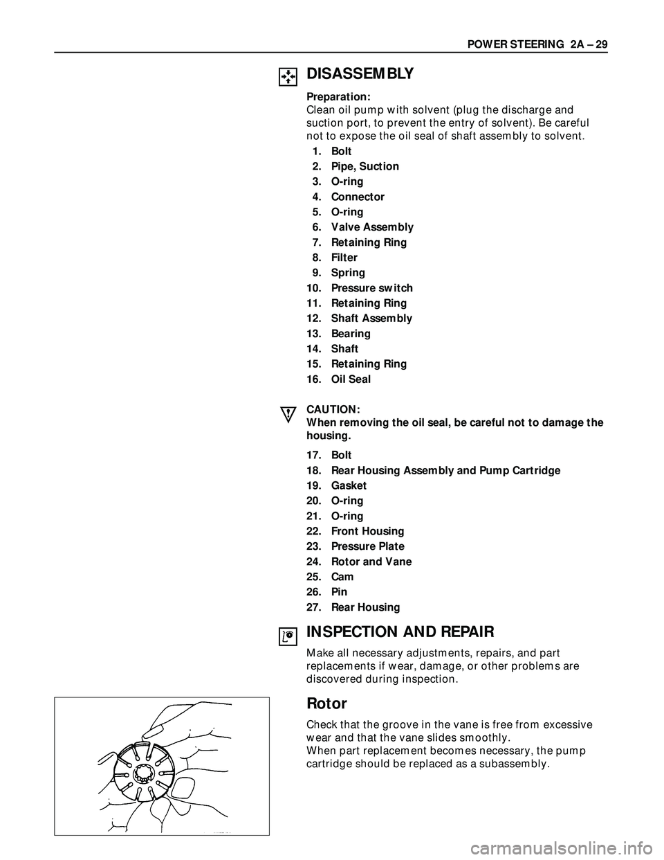
Rotor
Check that the groove in the vane is free from excessive
wear and that the vane slides smoothly.
When part replacement becomes necessary, the pump
cartridge should be replaced as a subassembly.
Page 333 of 3573

POWER STEERING 2A – 31
23. Pressure Plate
CAUTION:
When installing side plate, be careful not to damage its
inner surface. Damaged side plate may cause poor pump
performance, pump seizure or oil leakage.
22. Front Housing
21. O-ring
20. O-ring
Be sure to discard used O-rings, and always use new
parts for installation.
19. Gasket
Be sure to discard used parts, and always use new
parts for installation.
18. Rear Housing Assembly and Pump Cartridge
17. Bolt
Rear Housing Bolt Torque N·m (kg·m/lb·ft)
17.6 (1.8 / 12.8)
16. Oil Seal
Be sure to discard used parts, and always use new
parts for installation.
CAUTION:
When installing the oil seal, be careful not to damage the
oil seal contacting surface of the housing.
15. Retaining Ring
14. Shaft
13. Bearing
12. Shaft Assembly
11. Retaining Ring
10. Pressure switch
Pressure Switch Torque N·m (kg·m/lb·ft)
20 (2.0 / 14)
9. Spring
8. Filter
7. Retaining Ring
6. Valve
5. O-ring
Be sure to discard used parts, and always use new
parts for installation.
4. Connector
Connector Torque N·m (kg·m/lb·ft)
74 (7.5 / 54)
3. O-ring
Be sure to discard used parts, and always use new
parts for installation.
2. Pipe, Suction
1. Bolt
Suction Pipe Bolt Torque N·m (kg·m/lb·ft)
15.7 (1.6 / 11.5)
Page 334 of 3573
2A – 32 POWER STEERING
POWER STEERING PUMP (4JG2 Engine Model)
Disassembly Steps
1. Bolt
2. Pipe, suction
3. O-ring
4. O-ring
5. O-ring
6. Connector
7. O-ring
8. Valve
9. Retaining ring
10. Filter
11. Spring
12. Retaining ring
13. Shaft assembly
14. Bearing
15. Shaft16. Retaining ring
17. Oil seal
18. Bolt
19. Rear housing assembly and pump
cartridge
20. Gasket
21. O-ring
22. O-ring
23. Front housing
24. Pressure plate
25. Rotor and vane
26. Cam
27. Pin
28. Rear housing
Reassembly Steps
28. Rear housing
27. Pin
26. Cam
25. Rotor and vane
24. Pressure plate
23. Front housing
22. O-ring
21. O-ring
20. Gasket
19. Rear housing assembly and pump
cartridge
18. Bolt
17. Oil seal
16. Retaining ring
15. Shaft14. Bearing
13. Shaft assembly
12. Retaining ring
11. Spring
10. Filter
9. Retaining ring
8. Valve
7. O-ring
6. Connector
5. O-ring
4. O-ring
3. O-ring
2. Pipe, suction
1. Bolt
Page 335 of 3573
POWER STEERING 2A – 33
DISASSEMBLY
Preparation:
Clean oil pump with solvent (its plug discharge and
suction port to prevent the entry of solvent). Be careful not
to expose the oil seal of shaft assembly to solvent.
1. Bolt
2. Pipe, Suction
3. O-ring
4. O-ring
5. O-ring
6. Connector
7. O-ring
8. Valve
9. Retaining Ring
10. Filter
11. Spring
12. Retaining Ring
13. Shaft Assembly
14. Bearing
15. Shaft
16. Retaining Ring
17. Oil Seal
CAUTION:
When removing the oil seal, be careful not to damage the
housing.
18. Bolt
19. Rear Housing Assembly and Pump Cartridge
20. Gasket
21. O-ring
22. O-ring
23. Front Housing
24. Pressure Plate
25. Rotor and Vane
26. Cam
27. Pin
28. Rear Housing