Page 336 of 3573
2A – 34 POWER STEERING
REASSEMBLY
28. Rear Housing
27. Pin
26. Cam
25. Rotor and Vane
Install the rotor with its punch mark facing the front
housing.
Install the vane with curved face in contact with the
inner wall of the cam.
24. Pressure Plate
CAUTION:
When install pressure plate, be careful not to damage its
inner surface. Damaged pressure plate may cause poor
pump performance, pump seizure or oil leakage.
23. Front Housing
22. O-ring
Be sure to discard used parts, and always used new
parts for installation.
21. O-ring
Be sure to discard used parts, and always used new
parts for installation.
20. Gasket
Be sure to discard used parts, and always used new
parts for installation.
19. Rear Housing Assemble and Pump Cartridge
18. Bolt
Rear Housing Bolt Torque N·m (kg·m/lb·ft)
54 (5.5 / 40)
17. O-ring
Be sure to discard used parts, and always used new
parts for installation.
Page 337 of 3573
POWER STEERING 2A – 35
CAUTION:
When install pressure plate, be careful not to damage its
inner surface. Damaged pressure plate may cause poor
pump performance, pump seizure or oil leakage.
16. Retaining Ring
15. Shaft
14. Bearing
13. Shaft Assembly
12. Retaining Ring
11. Spring
10. Filter
9. Retaining Ring
8. Valve
7. O-ring
Be sure to discard used parts, and always used new
parts for installation.
6. Connector
Connector Torque N·m (kg·m/lb·ft)
54 (5.5 / 40)
5. O-ring
Be sure to discard used parts, and always used new
parts for installation.
4. O-ring
Be sure to discard used parts, and always used new
parts for installation.
3. O-ring
Be sure to discard used parts, and always used new
parts for installation.
2. Pipe, Suction
1. Bolt
Suction Pipe Bolt Torque N·m (kg·m/lb·ft)
21 (2.1 / 15)
Page 338 of 3573
2A – 36 POWER STEERING
POWER STEERING PUMP (4JX1 Engine Model)
17 1 18 227654
3 2
19
20 2115
14
16
8
10
12
11
13 9
23
Disassembly Steps
1. O-ring
2. Pipe, suction
3. O-ring
4. Connector
5. O-ring
6. Valve
7. Spring
8. Bolt
9. Rear housing assembly
10. O-ring
11. Pump cartridge
12. Cam13. Rotor and vane
14. Pressure plate
15. O-ring
16. O-ring
17. Gear
18. Retaining ring
19. Shaft assembly
20. Bearing
21. Shaft
22. Oil seal
23. Front housing
Reassembly Steps
23. Front housing
22. Oil seal
21. Shaft
20. Bearing
19. Shaft assembly
18. Retaining ring
17. Gear
16. O-ring
15. O-ring
14. Pressure plate
13. Rotor and vane
12. Cam11. Pump cartridge
10. O-ring
9. Rear housing assembly
8. Bolt
7. Spring
6. Valve
5. O-ring
4. Connector
3. O-ring
2. Pipe, suction
1. O-ring
412RW048
Page 339 of 3573
POWER STEERING 2A – 37
DISASSEMBLY
Preparation:
Clean oil pump with solvent (plug the discharge and
suction port to prevent the entry of solvent). Be careful not
to expose the oil seal of shaft assembly to solvent.
1. O-ring
2. Pipe, Suction
3. O-ring
4. Connector
5. O-ring
6. Valve
7. Spring
8. Bolt
9. Rear Housing Assembly
10. O-ring
11. Pump Cartridge
12. Cam
13. Rotor and Vane
14. Pressure Plate
15. O-ring
16. O-ring
17. Gear
18. Retaining Ring
19. Shaft Assembly
20. Bearing
21. Shaft
22. Oil seal
CAUTION:
When removing the oil seal, be careful not to damage the
housing.
23. Front Housing
Page 340 of 3573
2A – 38 POWER STEERING
REASSEMBLY
23. Front Housing
22. Oil Seal
Be sure to discard used parts, and always used new
parts for installation.
21. Shaft
20. Bearing
19. Shaft Assembly
18. Retaining Ring
17. Gear
16. O-ring
Be sure to discard used parts, and always used new
parts for installation.
15. O-ring
Be sure to discard used parts, and always used new
parts for installation.
14. Pressure Plate
CAUTION:
When install pressure plate, be careful not to damage its
inner surface. Damaged pressure plate may cause poor
pump performance, pump seizure or oil leakage.
13. Rotor and Vane
Install the vane with curved face in contact with the
inner wall of the cam.
12. Cam
11. Pump Cartridge
10. O-ring
Be sure to discard used parts, and always used new
parts for installation.
9. Rear Housing Assembly
8. Bolt
Rear Housing Bolt Torque N·m (kg·m/lb·ft)
24 (2.4 / 17)
Page 453 of 3573
 4A1±16
NOTE: Do not apply pressure to the roller cage and apply
pressure only to the inner race.
425RW048
5. Discard the used collapsible spacer and install a new
one.
6. Install")
DIFFERENTIAL (FRONT) 4A1±16
NOTE: Do not apply pressure to the roller cage and apply
pressure only to the inner race.
425RW048
5. Discard the used collapsible spacer and install a new
one.
6. Install pinion gear.
7. Install outer bearing.
8. Use oil seal installer 9±8522±1275±0 to install a new
oil seal that has been soaked in rear axle lubricant.
NOTE: Take care to use a front differential oil seal, NOT
the rear differential oil seal.
415RW024
9. Install dust cover.
10. Install flange.
11. Install flange nut.
1. Apply lubricant to the pinion threads.2. Tighten the nut to the specified torque using the
pinion flange holder 5±8840±2157±0.
Torque: 177±275N´m (18±28kg´m/130±203 lb ft)
NOTE: Discard used flange nut and install new one and
do not over tighten the flange nut.
425RW047
3. Adjust pinion bearing preload.
a. Measure the bearing preload by using a torque
meter. Note the scale reading required to
rotate the flange.
b. Continue tightening flange nut until the
specified starting torque is obtained.
Starting torque:
New bear-
ing 0.7±1.1 N´m(0.065±0.115kg´m/5.64±9.98 lb in)
Used bear-
ing 0.4±0.5N´m(0.033±0.057kg´m/2.86±4.94 Ib in)
425RS027
4. Using punch 5-8840-2293-0, stake the flange nut
at two points.
Page 483 of 3573

4. Place the shim on the drive pinion, with the chamfered
side turned towards the pinion head then install the
inner bearing onto the pinion using an installer
9±85")
4A2A±16
DIFFERENTIAL (REAR 220mm)
4. Place the shim on the drive pinion, with the chamfered
side turned towards the pinion head then install the
inner bearing onto the pinion using an installer
9±8522±1165±0 and a press.
NOTE: Do not apply pressure to the roller cage and apply
pressure only to the inner race.
425RW048
5. Discard the used collapsible spacer and install a new
one.
6. Install pinion gear.
7. Install outer bearing.
8. Use oil seal installer 5±8840±2165±0 to install a new
oil seal that has been soaked in rear axle lubricant.
NOTE: Take care to use a front differential oil seal, NOT
the rear differential oil seal.
415RW029
9. Install dust cover.
10. Install flange.
11. Install flange nut.
1. Apply lubricant to the pinion threads.2. Tighten the nut to the specified torque using the
pinion flange holder 5±8840±2157±0.
Torque: 245±294N´m (25.0±28.0kg´m/181±217 lb f
t)
NOTE: Discard used flange nut and install new one and
do not over tighten the flange nut.
425RW057
3. Adjust pinion bearing preload.
a. Measure the bearing preload by using a torque
meter. Note the scale reading required to
rotate the flange.
b. Continue tightening flange nut until the
specified starting torque is obtained.
Starting torque:
New bear-
ing 0.7±1.3 N´m(0.07-0.13kg´m/6.08±11.28 lb in)
Used bear-
ing 0.4±0.6N´m(0.04±0.06kg´m/3.04-5.64 Ib in)
425RS027
4. Using punch 5±8840±2293±0, stake the flange
nut at two points.
Page 494 of 3573
DIFFERENTIAL (REAR 220mm)
4A2A±27
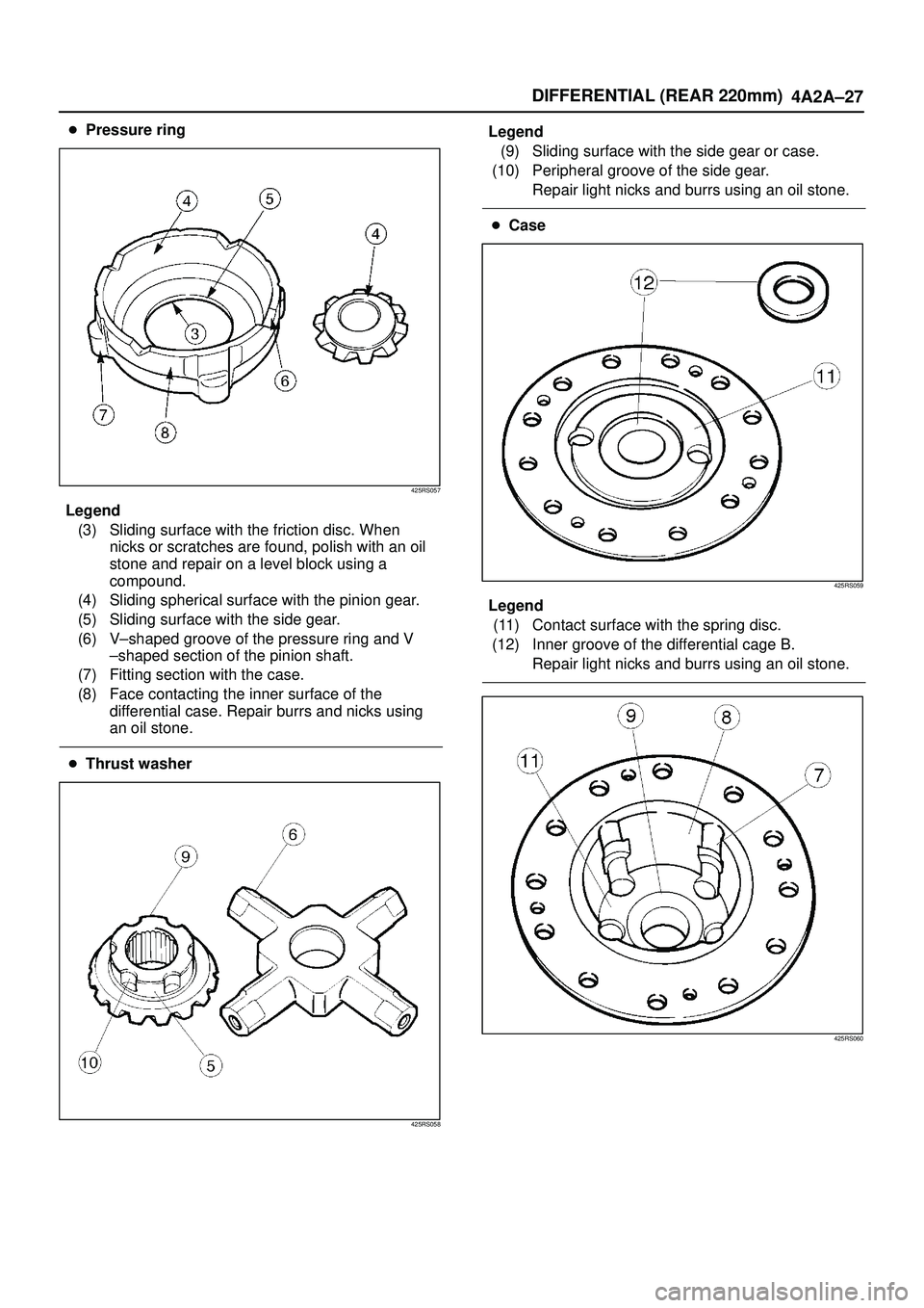
�Pressure ring
425RS057
Legend
(3) Sliding surface with the friction disc. When
nicks or scratches are found, polish with an oil
stone and repair on a level block using a
compound.
(4) Sliding spherical surface with the pinion gear.
(5) Sliding surface with the side gear.
(6) V±shaped groove of the pressure ring and V
±shaped section of the pinion shaft.
(7) Fitting section with the case.
(8) Face contacting the inner surface of the
differential case. Repair burrs and nicks using
an oil stone.
�Thrust washer
425RS058
Legend
(9) Sliding surface with the side gear or case.
(10) Peripheral groove of the side gear.
Repair light nicks and burrs using an oil stone.
�Case
425RS059
Legend
(11) Contact surface with the spring disc.
(12) Inner groove of the differential cage B.
Repair light nicks and burrs using an oil stone.
425RS060


17 1 18 227654
3 2
19
20 2115
14
16
8
10
12
11
13 9
23
Disassembly Steps
1. O-ring
2. Pipe, suction
3. O-ring
4. Connector
5. O-ring
6.")
. Be careful not
to expose the oil seal of shaft ass")