Page 2276 of 3573

TRANSMISSION CONTROL SYSTEM (4L30±E)7A1±31
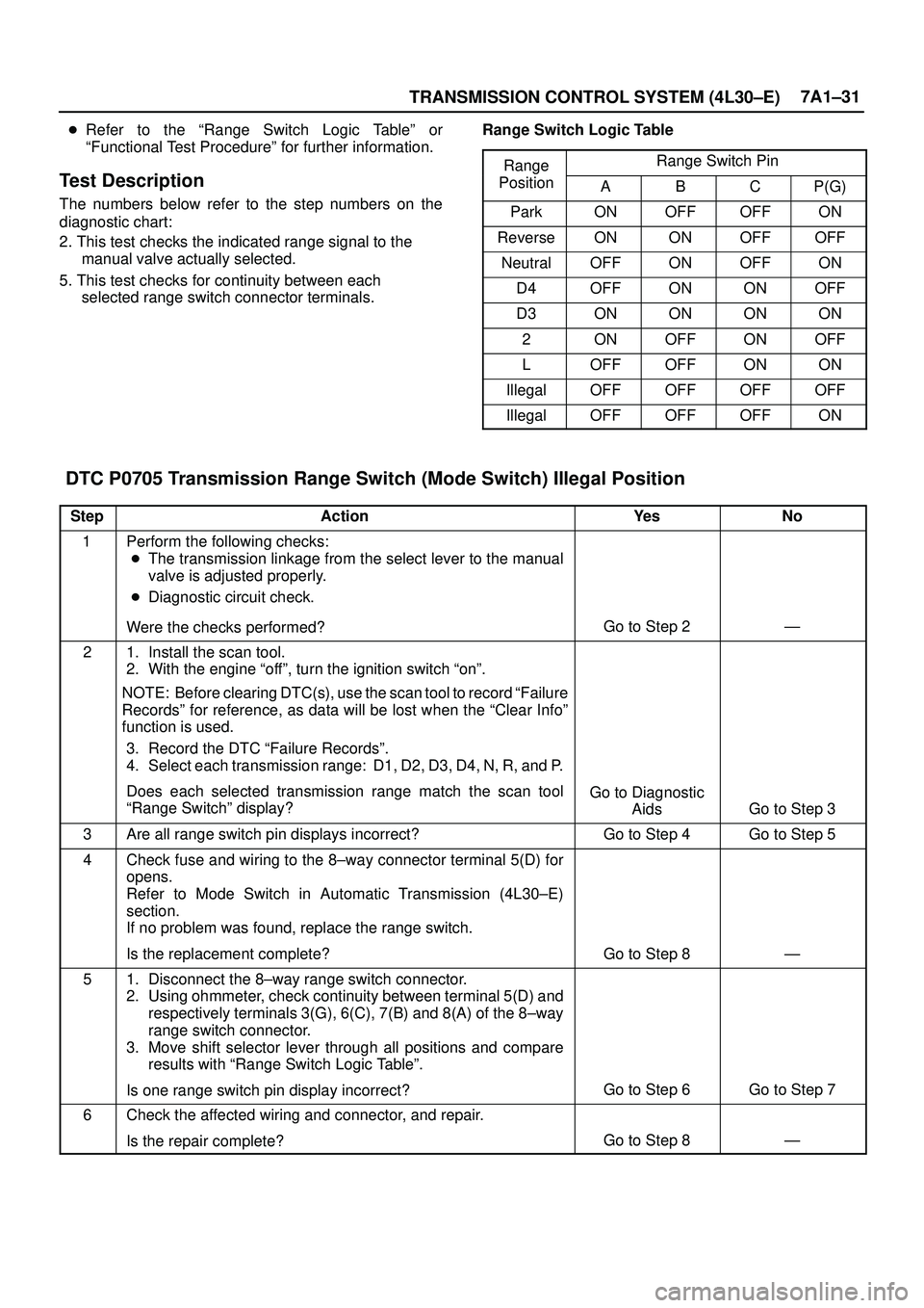
�Refer to the ªRange Switch Logic Tableº or
ªFunctional Test Procedureº for further information.
Test Description
The numbers below refer to the step numbers on the
diagnostic chart:
2. This test checks the indicated range signal to the
manual valve actually selected.
5. This test checks for continuity between each
selected range switch connector terminals.Range Switch Logic Table
Range
Range Switch Ping
PositionABCP(G)
ParkONOFFOFFON
ReverseONONOFFOFF
NeutralOFFONOFFON
D4OFFONONOFF
D3ONONONON
2ONOFFONOFF
LOFFOFFONON
IllegalOFFOFFOFFOFF
IllegalOFFOFFOFFON
DTC P0705 Transmission Range Switch (Mode Switch) Illegal Position
StepActionYe sNo
1Perform the following checks:
�The transmission linkage from the select lever to the manual
valve is adjusted properly.
�Diagnostic circuit check.
Were the checks performed?
Go to Step 2Ð
21. Install the scan tool.
2. With the engine ªoffº, turn the ignition switch ªonº.
NOTE: Before clearing DTC(s), use the scan tool to record ªFailure
Recordsº for reference, as data will be lost when the ªClear Infoº
function is used.
3. Record the DTC ªFailure Recordsº.
4. Select each transmission range: D1, D2, D3, D4, N, R, and P.
Does each selected transmission range match the scan tool
ªRange Switchº display?
Go to Diagnostic
Aids
Go to Step 3
3Are all range switch pin displays incorrect?Go to Step 4Go to Step 5
4Check fuse and wiring to the 8±way connector terminal 5(D) for
opens.
Refer to Mode Switch in Automatic Transmission (4L30±E)
section.
If no problem was found, replace the range switch.
Is the replacement complete?
Go to Step 8Ð
51. Disconnect the 8±way range switch connector.
2. Using ohmmeter, check continuity between terminal 5(D) and
respectively terminals 3(G), 6(C), 7(B) and 8(A) of the 8±way
range switch connector.
3. Move shift selector lever through all positions and compare
results with ªRange Switch Logic Tableº.
Is one range switch pin display incorrect?
Go to Step 6Go to Step 7
6Check the affected wiring and connector, and repair.
Is the repair complete?
Go to Step 8Ð
Page 2279 of 3573

7A1±34
TRANSMISSION CONTROL SYSTEM (4L30±E)
Diagnostic Aids
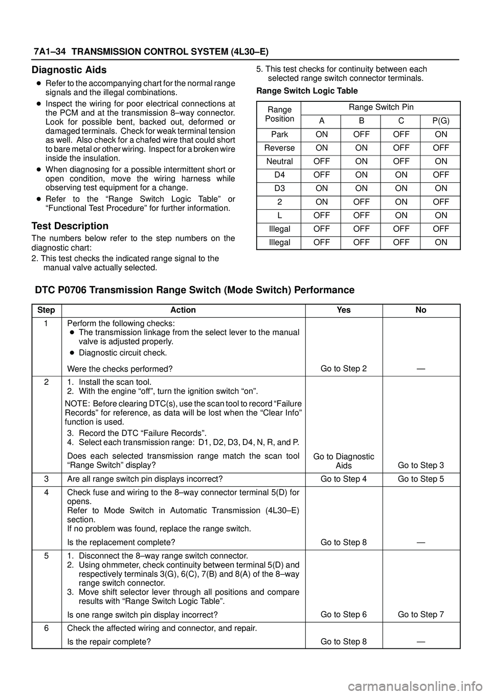
�Refer to the accompanying chart for the normal range
signals and the illegal combinations.
�Inspect the wiring for poor electrical connections at
the PCM and at the transmission 8±way connector.
Look for possible bent, backed out, deformed or
damaged terminals. Check for weak terminal tension
as well. Also check for a chafed wire that could short
to bare metal or other wiring. Inspect for a broken wire
inside the insulation.
�When diagnosing for a possible intermittent short or
open condition, move the wiring harness while
observing test equipment for a change.
�Refer to the ªRange Switch Logic Tableº or
ªFunctional Test Procedureº for further information.
Test Description
The numbers below refer to the step numbers on the
diagnostic chart:
2. This test checks the indicated range signal to the
manual valve actually selected.5. This test checks for continuity between each
selected range switch connector terminals.
Range Switch Logic Table
Range
Range Switch Ping
PositionABCP(G)
ParkONOFFOFFON
ReverseONONOFFOFF
NeutralOFFONOFFON
D4OFFONONOFF
D3ONONONON
2ONOFFONOFF
LOFFOFFONON
IllegalOFFOFFOFFOFF
IllegalOFFOFFOFFON
DTC P0706 Transmission Range Switch (Mode Switch) Performance
StepActionYe sNo
1Perform the following checks:
�The transmission linkage from the select lever to the manual
valve is adjusted properly.
�Diagnostic circuit check.
Were the checks performed?
Go to Step 2Ð
21. Install the scan tool.
2. With the engine ªoffº, turn the ignition switch ªonº.
NOTE: Before clearing DTC(s), use the scan tool to record ªFailure
Recordsº for reference, as data will be lost when the ªClear Infoº
function is used.
3. Record the DTC ªFailure Recordsº.
4. Select each transmission range: D1, D2, D3, D4, N, R, and P.
Does each selected transmission range match the scan tool
ªRange Switchº display?
Go to Diagnostic
Aids
Go to Step 3
3Are all range switch pin displays incorrect?Go to Step 4Go to Step 5
4Check fuse and wiring to the 8±way connector terminal 5(D) for
opens.
Refer to Mode Switch in Automatic Transmission (4L30±E)
section.
If no problem was found, replace the range switch.
Is the replacement complete?
Go to Step 8Ð
51. Disconnect the 8±way range switch connector.
2. Using ohmmeter, check continuity between terminal 5(D) and
respectively terminals 3(G), 6(C), 7(B) and 8(A) of the 8±way
range switch connector.
3. Move shift selector lever through all positions and compare
results with ªRange Switch Logic Tableº.
Is one range switch pin display incorrect?
Go to Step 6Go to Step 7
6Check the affected wiring and connector, and repair.
Is the repair complete?
Go to Step 8Ð
Page 2285 of 3573

7A1±40
TRANSMISSION CONTROL SYSTEM (4L30±E)
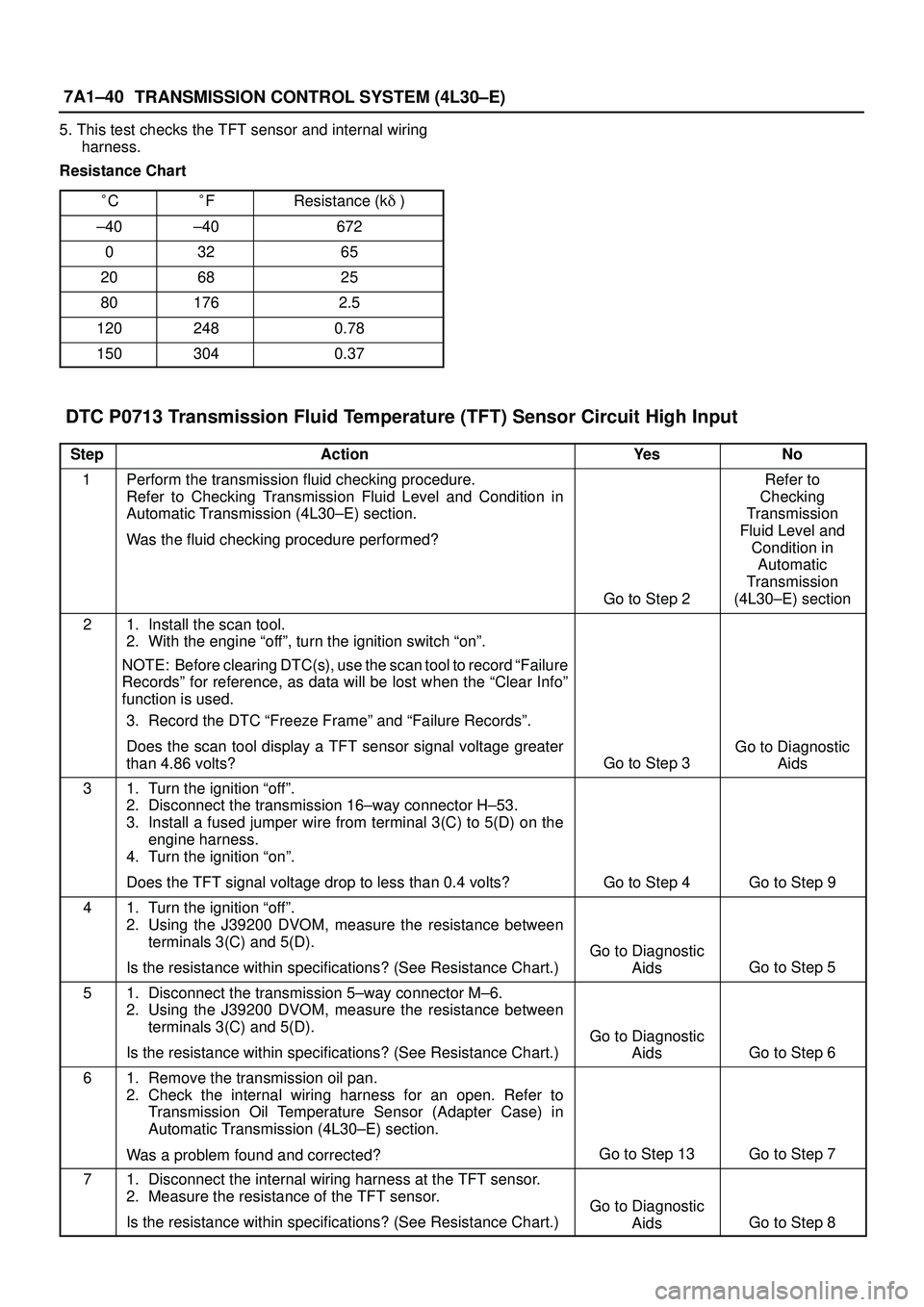
5. This test checks the TFT sensor and internal wiring
harness.
Resistance Chart
�C
�FResistance (k�)
±40±40672
03265
206825
801762.5
1202480.78
1503040.37
DTC P0713 Transmission Fluid Temperature (TFT) Sensor Circuit High Input
StepActionYe sNo
1Perform the transmission fluid checking procedure.
Refer to Checking Transmission Fluid Level and Condition in
Automatic Transmission (4L30±E) section.
Was the fluid checking procedure performed?
Go to Step 2
Refer to
Checking
Transmission
Fluid Level and
Condition in
Automatic
Transmission
(4L30±E) section
21. Install the scan tool.
2. With the engine ªoffº, turn the ignition switch ªonº.
NOTE: Before clearing DTC(s), use the scan tool to record ªFailure
Recordsº for reference, as data will be lost when the ªClear Infoº
function is used.
3. Record the DTC ªFreeze Frameº and ªFailure Recordsº.
Does the scan tool display a TFT sensor signal voltage greater
than 4.86 volts?
Go to Step 3
Go to Diagnostic
Aids
31. Turn the ignition ªoffº.
2. Disconnect the transmission 16±way connector H±53.
3. Install a fused jumper wire from terminal 3(C) to 5(D) on the
engine harness.
4. Turn the ignition ªonº.
Does the TFT signal voltage drop to less than 0.4 volts?
Go to Step 4Go to Step 9
41. Turn the ignition ªoffº.
2. Using the J39200 DVOM, measure the resistance between
terminals 3(C) and 5(D).
Is the resistance within specifications? (See Resistance Chart.)
Go to Diagnostic
Aids
Go to Step 5
51. Disconnect the transmission 5±way connector M±6.
2. Using the J39200 DVOM, measure the resistance between
terminals 3(C) and 5(D).
Is the resistance within specifications? (See Resistance Chart.)
Go to Diagnostic
Aids
Go to Step 6
61. Remove the transmission oil pan.
2. Check the internal wiring harness for an open. Refer to
Transmission Oil Temperature Sensor (Adapter Case) in
Automatic Transmission (4L30±E) section.
Was a problem found and corrected?
Go to Step 13Go to Step 7
71. Disconnect the internal wiring harness at the TFT sensor.
2. Measure the resistance of the TFT sensor.
Is the resistance within specifications? (See Resistance Chart.)
Go to Diagnostic
Aids
Go to Step 8
Page 2727 of 3573
8DÐ134 WIRING SYSTEM
Diagnosis
Quick Chart for Check Points
1. Headlight (RHD)
Check point
Trouble modeFuse
F–4
(15A)F–5
(15A)Lighting
relayLighting
SWDimmer•
Passing
SWCable
harness Headlight
bulb
1–1. Both Headlights inoperative
1–2. Headlight on the left (or
right) side inoperative
1–3. Both headlights in
low-beam inoperative
1–4. Headlight low-beam on
the left (or right) side
inoperative
1–5. Both headlights in
high–beam inoperative
1–6. Headlight high-beam on the
left (or right) side
inoperative
1–7. Headlight beam does not
change
LH RH
1–8. Headlights remain on when
the lighting SW is turned off
1–9. Headlights come on with
the lighting SW at the
clearance light position
1–10. Passing lights inoperative
Page 2749 of 3573
8DÐ156 WIRING SYSTEM
Diagnosis
Quick Chart for Check Points
Trouble modeCheck point
Both actuators inoperative
Actuator on the left (or right) side inoperative
Actuator on the left (or right) side does not
stop
1.
2.
3.
Fuse C-4 (10A) Leveling SWActuator
Cable harnessLH RH
Page 2761 of 3573

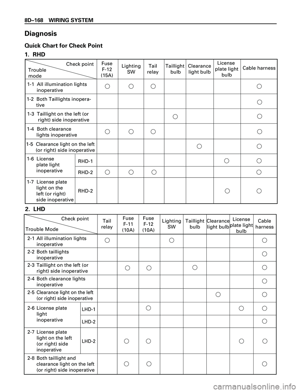
8DÐ168 WIRING SYSTEM
Diagnosis
Quick Chart for Check Point
1. RHD
2. LHD
Trouble
modeCheck point
RHD-1
RHD-2
RHD-2
Fuse
F-12
(15A)Lighting
SWTail
relayClearance
light bulbLicense
plate light
bulbCable harness
1-3 Taillight on the left (or
right) side inoperative
1-4 Both clearance
lights inoperative
1-5
Clearance light on the left
(or right) side inoperative
1-6 License
plate light
inoperative
1-7 License plate
light on the
left (or right)
side inoperative
1-1 All illumination lights
inoperative
1-2 Both Taillights inopera-
tive
Taillight
bulb
Trouble ModeCheck pointFuse
F-12
(10A)Lighting
SWTaillight
bulbClearance
light bulbLicense
plate light
bulbCable
harness
2-1All illumination lights
inoperative
2-2Both taillights
inoperative
2-3Taillight on the left (or
right) side inoperative
2-4Both clearance lights
inoperative
2-5Clearance light on the left
(or right) side inoperative
2-6LHD-1
LHD-2
LHD-2License plate
light
inoperative
2-7 License plate
light on the left
(or right) side
inoperative
Fuse
F-11
(10A) Tail
relay
2-8
Both taillight and
clearance light on the left
(or right) side inoperative
Page 2795 of 3573
8DÐ202 WIRING SYSTEM
Diagnosis
Quick Chart for Check Points
Check pointFuse
C-3
(10A)F-3
(15A)Turn
signal
SWHazard
SWFlasher
unitTurn
signal
bulbCable
harness
1 Both turn signal lights and hazard
warning lights inoperativeTrouble mode
2 Turn signal light flashes too quickly
3 Hazard warning lights inoperative
4 Turn signal lights inoperative
5 Turn signal lights on the right (or left) side
inoperative
6 Hazard warning lights on the right (or left)
side inoperative
7 Turn signal lights and hazard warning
ligths on the right (or left) side inoperative
Page 2809 of 3573
8DÐ216 WIRING SYSTEM
DIAGNOSIS
Quick Chart for Check Points
Check pointFuse
C-14 (15A)Cable
harness
1 Both stoplights inoperative Trouble mode
2 Stoplight on the left (or right) side inoperative
Stoplight
SW or
brake SWStoplight
bulb
High mounted stoplight inoperative3
High mount
stoplight
ASM