1998 ISUZU TROOPER drive shaft
[x] Cancel search: drive shaftPage 272 of 3573
1D Ð 16 COMPRESSOR OVERHAUL
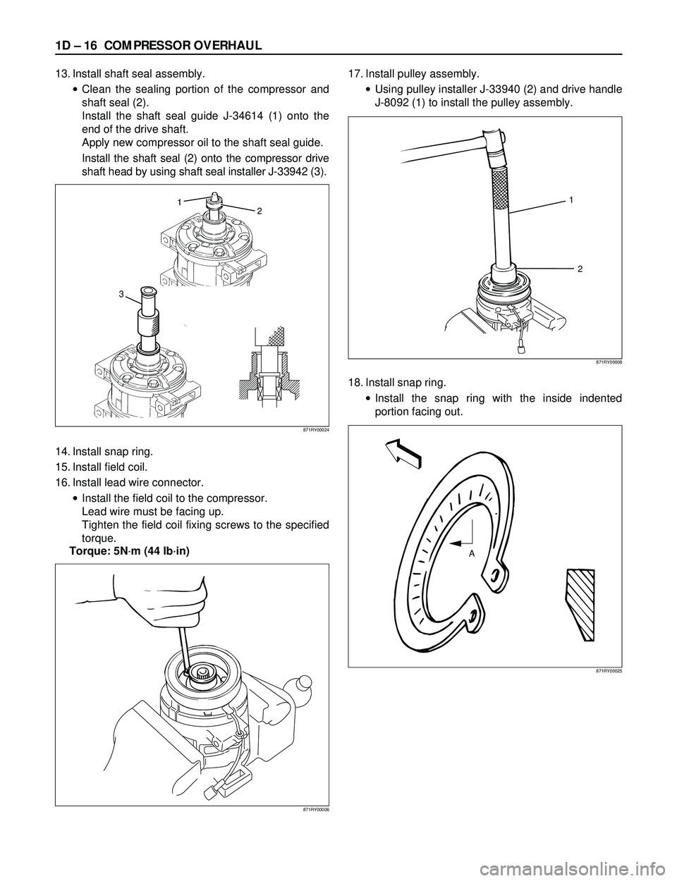
13. Install shaft seal assembly.
·Clean the sealing portion of the compressor and
shaft seal (2).
Install the shaft seal guide J-34614 (1) onto the
end of the drive shaft.
Apply new compressor oil to the shaft seal guide.
Install the shaft seal (2) onto the compressor drive
shaft head by using shaft seal installer J-33942 (3).
14. Install snap ring.
15. Install field coil.
16. Install lead wire connector.
·Install the field coil to the compressor.
Lead wire must be facing up.
Tighten the field coil fixing screws to the specified
torque.
Torque: 5Nám (44 lbáin)17. Install pulley assembly.
·Using pulley installer J-33940 (2) and drive handle
J-8092 (1) to install the pulley assembly.
18. Install snap ring.
·Install the snap ring with the inside indented
portion facing out.
871RY00006
32 1
871RY00024
A
871RY00025
1
2
871RY00008
Page 273 of 3573
COMPRESSOR OVERHAUL 1D Ð 17
19. Install shim(s).
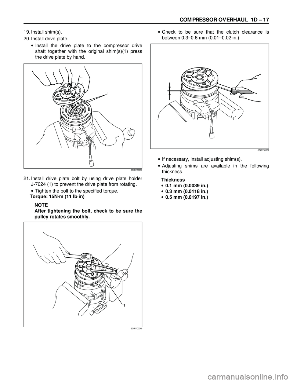
20. Install drive plate.
·Install the drive plate to the compressor drive
shaft together with the original shim(s)(1) press
the drive plate by hand.
21. Install drive plate bolt by using drive plate holder
J-7624 (1) to prevent the drive plate from rotating.
·Tighten the bolt to the specified torque.
Torque: 15Nám (11 lbáin)
NOTE
After tightening the bolt, check to be sure the
pulley rotates smoothly.·Check to be sure that the clutch clearance is
between 0.3Ð0.6 mm (0.01Ð0.02 in.)
·If necessary, install adjusting shim(s).
·Adjusting shims are available in the following
thickness.
Thickness
·0.1 mm (0.0039 in.)
·0.3 mm (0.0118 in.)
·0.5 mm (0.0197 in.)
1
871RY00009
871RY00007
1
901RY00010
Page 274 of 3573
1D Ð 18 COMPRESSOR OVERHAUL
HD6 TYPE COMPRESSOR
Metric Thread Size Information
Compressor to mounting bracket bolts (Front)
M10´ 1.5 Ð 6H
Compressor to mounting bracket bolts (Rear)
M8´ 1.25 Ð 6H
Suction-discharge port screw
M10´ 1.5 Ð 6HCompressor shaft
M9´ 1.25 Ð 6H
Internal hub-clutch drive assembly
M22´ 1.5 Ð 6H
COMPRESSOR CLUTCH PLATE AND HUB
ASSEMBLY
Removal
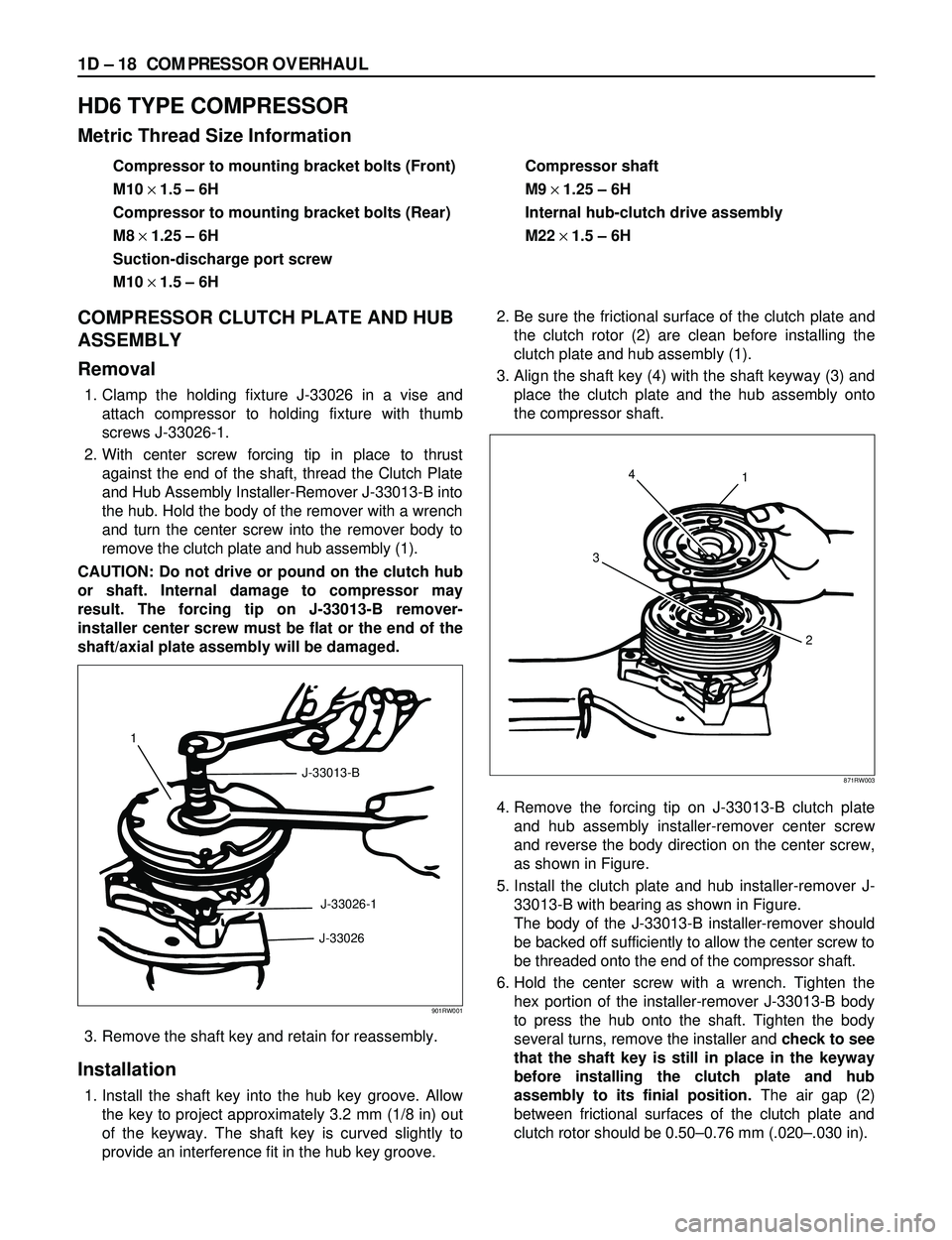
1. Clamp the holding fixture J-33026 in a vise and
attach compressor to holding fixture with thumb
screws J-33026-1.
2. With center screw forcing tip in place to thrust
against the end of the shaft, thread the Clutch Plate
and Hub Assembly Installer-Remover J-33013-B into
the hub. Hold the body of the remover with a wrench
and turn the center screw into the remover body to
remove the clutch plate and hub assembly (1).
CAUTION: Do not drive or pound on the clutch hub
or shaft. Internal damage to compressor may
result. The forcing tip on J-33013-B remover-
installer center screw must be flat or the end of the
shaft/axial plate assembly will be damaged.
3. Remove the shaft key and retain for reassembly.
Installation
1. Install the shaft key into the hub key groove. Allow
the key to project approximately 3.2 mm (1/8 in) out
of the keyway. The shaft key is curved slightly to
provide an interference fit in the hub key groove.2. Be sure the frictional surface of the clutch plate and
the clutch rotor (2) are clean before installing the
clutch plate and hub assembly (1).
3. Align the shaft key (4) with the shaft keyway (3) and
place the clutch plate and the hub assembly onto
the compressor shaft.
4. Remove the forcing tip on J-33013-B clutch plate
and hub assembly installer-remover center screw
and reverse the body direction on the center screw,
as shown in Figure.
5. Install the clutch plate and hub installer-remover J-
33013-B with bearing as shown in Figure.
The body of the J-33013-B installer-remover should
be backed off sufficiently to allow the center screw to
be threaded onto the end of the compressor shaft.
6. Hold the center screw with a wrench. Tighten the
hex portion of the installer-remover J-33013-B body
to press the hub onto the shaft. Tighten the body
several turns, remove the installer and check to see
that the shaft key is still in place in the keyway
before installing the clutch plate and hub
assembly to its finial position.The air gap (2)
between frictional surfaces of the clutch plate and
clutch rotor should be 0.50Ð0.76 mm (.020Ð.030 in).
1
J-33013-B
J-33026-1
J-33026
901RW001
4
31
2
871RW003
Page 275 of 3573
COMPRESSOR OVERHAUL 1D Ð 19
CAUTION: If the center screw is threaded fully onto
the end of the compressor shaft. or if the body of
the installer is held and the center screw is rotated,
the key will wedge and will break the clutch hub.7. Remove installer J-33013-B, check for proper
positioning of the shaft key (even or slightly above
the clutch hub).
8. Spin the pulley rotor by hand to see that the rotor is
not rubbing the clutch drive plate.
COMPRESSOR CLUTCH ROTOR AND/OR
BEARING
Removal
1. Remove the clutch plate and hub assembly as
described previously.
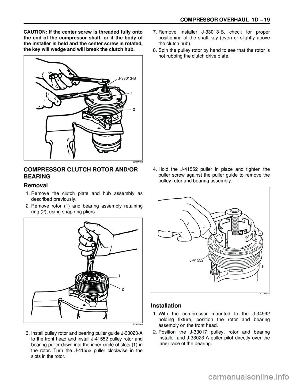
2. Remove rotor (1) and bearing assembly retaining
ring (2), using snap ring pliers.
3. Install pulley rotor and bearing puller guide J-33023-A
to the front head and install J-41552 pulley rotor and
bearing puller down into the inner circle of slots (1) in
the rotor. Turn the J-41552 puller clockwise in the
slots in the rotor.4. Hold the J-41552 puller in place and tighten the
puller screw against the puller guide to remove the
pulley rotor and bearing assembly.
Installation
1. With the compressor mounted to the J-34992
holding fixture, position the rotor and bearing
assembly on the front head.
2. Position the J-33017 pulley, rotor and bearing
installer and J-33023-A puller pilot directly over the
inner race of the bearing.
1
2 J-33013-B
901RW002
1
2
901RW003
J-41552
1
871RW007
Page 281 of 3573
COMPRESSOR OVERHAUL 1D Ð 25
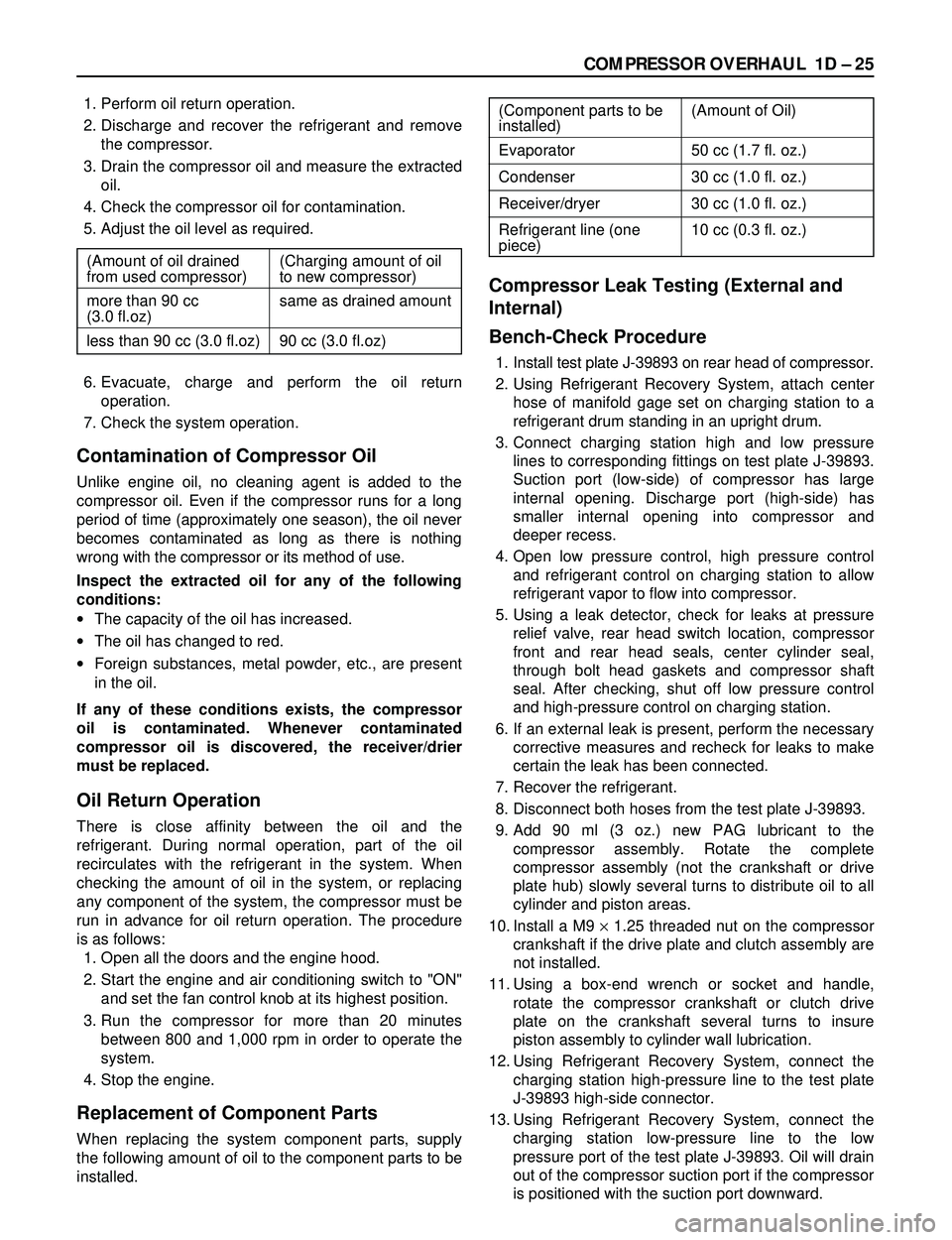
1. Perform oil return operation.
2. Discharge and recover the refrigerant and remove
the compressor.
3. Drain the compressor oil and measure the extracted
oil.
4. Check the compressor oil for contamination.
5. Adjust the oil level as required.
6. Evacuate, charge and perform the oil return
operation.
7. Check the system operation.
Contamination of Compressor Oil
Unlike engine oil, no cleaning agent is added to the
compressor oil. Even if the compressor runs for a long
period of time (approximately one season), the oil never
becomes contaminated as long as there is nothing
wrong with the compressor or its method of use.
Inspect the extracted oil for any of the following
conditions:
·The capacity of the oil has increased.
·The oil has changed to red.
·Foreign substances, metal powder, etc., are present
in the oil.
If any of these conditions exists, the compressor
oil is contaminated. Whenever contaminated
compressor oil is discovered, the receiver/drier
must be replaced.
Oil Return Operation
There is close affinity between the oil and the
refrigerant. During normal operation, part of the oil
recirculates with the refrigerant in the system. When
checking the amount of oil in the system, or replacing
any component of the system, the compressor must be
run in advance for oil return operation. The procedure
is as follows:
1. Open all the doors and the engine hood.
2. Start the engine and air conditioning switch to "ON"
and set the fan control knob at its highest position.
3. Run the compressor for more than 20 minutes
between 800 and 1,000 rpm in order to operate the
system.
4. Stop the engine.
Replacement of Component Parts
When replacing the system component parts, supply
the following amount of oil to the component parts to be
installed.
Compressor Leak Testing (External and
Internal)
Bench-Check Procedure
1. Install test plate J-39893 on rear head of compressor.
2. Using Refrigerant Recovery System, attach center
hose of manifold gage set on charging station to a
refrigerant drum standing in an upright drum.
3. Connect charging station high and low pressure
lines to corresponding fittings on test plate J-39893.
Suction port (low-side) of compressor has large
internal opening. Discharge port (high-side) has
smaller internal opening into compressor and
deeper recess.
4. Open low pressure control, high pressure control
and refrigerant control on charging station to allow
refrigerant vapor to flow into compressor.
5. Using a leak detector, check for leaks at pressure
relief valve, rear head switch location, compressor
front and rear head seals, center cylinder seal,
through bolt head gaskets and compressor shaft
seal. After checking, shut off low pressure control
and high-pressure control on charging station.
6. If an external leak is present, perform the necessary
corrective measures and recheck for leaks to make
certain the leak has been connected.
7. Recover the refrigerant.
8. Disconnect both hoses from the test plate J-39893.
9. Add 90 ml (3 oz.) new PAG lubricant to the
compressor assembly. Rotate the complete
compressor assembly (not the crankshaft or drive
plate hub) slowly several turns to distribute oil to all
cylinder and piston areas.
10. Install a M9 ´1.25 threaded nut on the compressor
crankshaft if the drive plate and clutch assembly are
not installed.
11. Using a box-end wrench or socket and handle,
rotate the compressor crankshaft or clutch drive
plate on the crankshaft several turns to insure
piston assembly to cylinder wall lubrication.
12. Using Refrigerant Recovery System, connect the
charging station high-pressure line to the test plate
J-39893 high-side connector.
13. Using Refrigerant Recovery System, connect the
charging station low-pressure line to the low
pressure port of the test plate J-39893. Oil will drain
out of the compressor suction port if the compressor
is positioned with the suction port downward. (Component parts to be (Amount of Oil)
installed)
Evaporator 50 cc (1.7 fl. oz.)
Condenser 30 cc (1.0 fl. oz.)
Receiver/dryer 30 cc (1.0 fl. oz.)
Refrigerant line (one 10 cc (0.3 fl. oz.)
piece)
(Amount of oil drained (Charging amount of oil
from used compressor) to new compressor)
more than 90 cc same as drained amount
(3.0 fl.oz)
less than 90 cc (3.0 fl.oz) 90 cc (3.0 fl.oz)
Page 282 of 3573
1D Ð 26 COMPRESSOR OVERHAUL
14. Attach the compressor to the J-34992 holding
fixture and mount the compressor in a vise so that
the compressor will be in a horizontal position and
the shaft can be turned with a wrench.
15. Using a wrench, rotate the compressor crankshaft
or drive plate hub ten complete revolutions at a
speed of approximately one-revolution per second
turning the compressor at less than one-revolution
per second can result in a lower pump-up pressure
and disqualify a good pumping compressor.
16. Observe the reading on high-pressure gauge at the
completion of the tenth revolution of the
compressor. The pressure reading for a good
pumping compressor should be 690 kPa (100 psi)
or above. A pressure reading of less than 620 kPa
(90 psi) would indicate one or more suction and/or
discharge valves leaking an internal leak, or an
inoperative valve, and the refrigerant must be
recovered and the compressor disassembled and
checked for cause of leak. Repair as needed,
reassemble and repeat the pump-up test. Externally
leak test.
17. When the pressure pump-up test is completed,
recover the refrigerant from the high-side and
remove the test plate J-39893.
18. Tilt the compressor so that the compressor suction
and discharge ports are down. Drain the PAG
lubricant from the compressor.
19. Allow the compressor to drain for 10 minutes, then
refill with the proper amount of PAG lubricant, per
oil balance procedure described previously. The
PAG lubricant may be poured into the suction port.
If further assembly or processing is required, a
shipping plate or test plate J-39893 should be
installed to keep out air, dirt and moisture until the
compressor is installed.
Page 287 of 3573

SERVICE INFORMATION 00 – 5
Problem Possible Cause Correction
GENERAL TROUBLESHOOTING (CONT.)
Wheel Tramp or Hop
Hard Steering
Too Much Play In
Steering
Poor Steering Wheel
Returnability
Abnormal Noise1. Blister or bump on tire.
2. Improper shock absorber operation
1. Bind in steering linkage ball studs,
upper or lower end ball joint.
2. Improper wheel alignment.
3. Steering gear misadjustment.
4. Tire not adequately inflated.
5. Bind in steering column or shaft.
6. Improper power steering system
operation.
1. Wheel bearings worn.
2. Loose steering gear or linkage.
3. Steering gear misadjustment.
4. Worn or loose steering shaft universal
joint.
5. Worn steering linkage ball joints.
6. Worn upper or lower end ball joints.
1. Bind in steering linkage ball joints.
2. Bind in upper or lower end ball joints.
3. Bind in steering column and shaft.
4. Bind in steering gear.
5. Improper wheel alignment.
6. Tires not adequately inflated.
7. Loose steering wheel nut.
8. Worn wheel bearing.
1. Worn, sticky or loose upper or lower
end ball joint, steering linkage ball
joints or drive axle joints.
2. Faulty shock absorbers.
3. Worn upper or lower control arm bushing.
4. Loose stabilizer bar.
5. Loose wheel nuts.
6. Loose suspension bolts or nuts.
7. Broken or otherwise damaged wheel
bearings.
8. Broken suspension springs.
9. Loose steering gear.
10. Faulty steering gear.Replace tire.
Replace shock absorber.
Replace ball joints.
Check wheel alignment.
Check and adjust steering gear
preload.
Inflate tires to proper pressure.
Repair or replace.
Repair or replace.
Refer to "Power steering
system troubleshooting."
Replace wheel bearings.
Retighten or repair.
Inspect and adjust steering
gear preload.
Retighten or replace steering
shaft.
Replace ball joints.
Replace ball joints.
Replace ball joints.
Replace ball joints.
Repair or replace.
Check and repair steering gear.
Adjust wheel alignment.
Adjust tire pressure.
Retighten.
Replace.
Replace.
Replace or repair.
Replace.
Retighten bolts.
Tighten nuts. Check for
elongated wheel nut holes.
Replace wheel if required.
Retighten suspension bolts or
nuts.
Replace wheel bearing.
Replace spring.
Retighten mounting bolt.
Check and adjust steering gear.
Page 354 of 3573
This steering wheel and column repair section
covers the Supplemental Restraint System (SRS)
steering column. The following repair procedures
are specific to SRS Components. When servicing a
vehicle equipped with Supplemental Restraint
System, pay close attention to all WARNINGS and
CAUTIONS.
For detailed explanation about SRS, refer to Section
9J "SUPPLEMENTAL RESTRAINT SYSTEM (SRS)"
of manual.
The steering column has three important features in
addition to the steering function:
1. The column is energy absorbing, designed to
compress in a front-end collision to minimize
the possibility of injury to the driver of the
vehicle.
2. The ignition switch and lock are mounted
conveniently on the column.
3. With the column mounted lock, the ignition
and steering operation can be locked to
prevent theft of the vehicle.
The column may be disassembled and
reassembled. To insure the energy absorbing
action, it is important that the specified screws,
bolts and nuts be used only as designated and that
they are tightened to the specified torque.
When the column is removed from the vehicle, a
sharp blow on the end of steering shaft or shift
lever, leaning on the column assembly, or dropping
the assembly could shear or loosen the fasteners
that maintain column rigidity.
WARNING
THIS VEHICLE HAS A SUPPLEMENTAL RE-
STRAINT SYSTEM (SRS).REFER TO THE SRS
COMPONENT AND WIRING LOCATION VIEW
IN ORDER TO DETERMINE WHETHER YOU ARE
PERFORMING SERVICE ON OR NEAR THE SRS
COMPONENTS OR THE SRS WIRING. WHEN
YOU ARE PERFORMING SERVICE ON OR NEAR
THE SRS COMPONENTS OR THE SRS WIRING,
REFER TO THE SRS SERVICE INFORM ATION.
FAILURE TO FOLLOW WARNINGS COULD RE-
SULT IN POSSIBLE AIR BAG DEPLOYMENT,
PERSONAL INJURY, OR OTHERWISE UN-
NEEDED SRS SYSTEM REPAIRS.
SAFE HANDLING OF INFLATOR MODULES
REQUIRES FOLLOWING THE PROCEDURES
DESCRIBED BELOW FOR BOTH LIVE AND
DEPLOYED MODULES.
SAFETY PRECAUTIONS MUST BE FOLLOWEDWHEN HANDLING A DEPLOYED AIR BAG AS-
SEMBLY (AIR BAG). AFTER DEPLOYMENT,
THE AIR BAG ASSEMBLY (AIR BAG) SURFACE
MAY CONTAIN A SMALL AMOUNT OF SODIUM
HYDROXIDE, A BY-PRODUCT OF THE DEPLOY-
MENT REACTION, THAT IS IRRITATING TO THE
SKIN AND EYES.MOST OF THE POWDER ON
THE AIR BAG ASSEMBLY (AIR BAG) IS HARM-
LESS. AS A PRECAUTION, WEAR GLOVES
AND SAFETY GLASSES WHEN HANDLING A
DEPLOYED AIR BAG ASSEMBLY, AND WASH
YOUR HANDS WITH MILD SOAP AND WATER
AFTERWARDS.
WHEN CARRYING A LIVE AIR BAG ASSEMBLY,
MAKE SURE THE BAG AND TRIM COVER ARE
POINTED AWAY FROM YOU. NEVER CARRY
AN AIR BAG ASSEMBLY BY THE WIRES OR
CONNECTOR ON THE UNDERSIDE OF MODULE.
IN THE CASE OF AN ACCIDENTAL DEPLOY-
MENT, THE BAG WILL THEN DEPLOY WITH
MINIMAL CHANCE OF INJURY. WHEN PLACING
A LIVE AIR BAG ASSEMBLY ON A BENCH OR
OTHER SURFACE, ALWAYS FACE THE BAG AND
TRIM COVER UP, AWAY FROM THE SURFACE.
NEVER REST A STEERING COLUMN ASSEMBLY
ON THE STEERING WHEEL WITH THE AIR
BAG ASSEMBLY FACE DOWN AND COLUMN
VERTICAL.THIS IS NECESSARY SO THAT A
FREE SPACE IS PROVIDED TO ALLOW THE AIR
BAG ASSEMBLY TO EXPAND IN THE UNLIKELY
EVENT OF ACCIDENTAL DEPLOYMENT. OTHER-
WISE, PERSONAL INJURY COULD RESULT.
TO AVOID DEPLOYMENT WHEN TROUBLE
SHOOTING THE SRS SYSTEM, DO NOT USE
ELECTRICAL TEST EQUIPMENT, SUCH AS
BATTERY-POWERED OR A/C-POWERED VOLT-
METER, OHMMETER, ETC., OR ANY TYPE OF
ELECTRICAL EQUIPMENT OTHER THAN SPECI-
FIED IN THIS MANUAL. DO NOT USE A NON-
POWERED PROBE-TYPE TESTER.
INSTRUCTIONS IN THIS MANUAL MUST BE
FOLLOWED CAREFULLY, OTHERWISE PER-
SONAL INJURY MAY RESULT. 2A – 52 SUPPLEMENTAL RESTRAINT SYSTEM STEERING WHEEL & COLUMN
GENERAL DESCRIPTION