Page 2332 of 3573
.
Torque: 41 N´m (4.2kg´m/30 Ib ft)
8. Install the third cross")
7B±14MANUAL TRANSMISSION
7. Install the engine rear mount to the transmission case
and tighten the fixing bolts specified torque (6VE1).
Torque: 41 N´m (4.2kg´m/30 Ib ft)
8. Install the third crossmember to the frame and tighten
the fixing bolts specified torque.
Torque: 50 N´m (5.1kg´m/37 Ib ft)
9. Tighten the engine rear mount nuts specified torque.
Torque: 50 N´m (5.1kg´m/37 Ib ft)
10. Remove the transmission jack.
11. Apply the grease to top hole portion of the shift fork.
12. Install the slave cylinder and tighten the fixing bolts
specified torque.
Torque: 43 N´m (4.4kg´m/32 Ib ft)
13. Install the clutch dust cover to the clutch housing and
tighten the fixing bolts specified torque.
Torque: 8 N´m (0.8kg´m/69 Ib in)
220RS007
14. Install the slave cylinder heat protector to the slave
cylinder.
15. Install bracket and two transmission harness clamps
to the transmission case (6VE1).
16. Install harness heat protector (6VE1).(6VE1)
225RW006
17. Install four fuel pipe bracket (6VE1).
Page 2336 of 3573
7B±18MANUAL TRANSMISSION
Transmission (AR-5)
Disassembled View
226RW182
Legend
(1) Snap Ring
(2) Bearing
(3) Top Gear Shaft
(4) Block Ring
(5) Roller Bearing
(6) Snap Ring
(7) Clutch Hub No.2 Assembly
(8) 3rd Block Ring
(9) 3rd Gear
(10) 3rd Gear Needle Roller Bearing
(11) Mainshaft
(12) Thrust Washer Pin
(13) 2nd Gear Needle Roller Bearing
(14) 2nd Gear
(15) Synchronizer Assembly(16) Clutch Hub No.1 Assembly
(17) Snap Ring
(18) Synchronizer Assembly
(19) 1st Gear
(20) 1st Gear Bearing Spacer
(21) 1st Gear Needle Roller Bearing
(22) 1st Gear Thrust Washer
(23) Mainshaft Bearing
(24) Snap Ring
(25) 5th Gear
(26) Snap Ring
(27) Intermediate Plate
(28) Bearing Retainer
(29) Snap Ring
(30) Front Bearing Assembly
(31) Counter Gear Shaft
Page 2338 of 3573
7B±20MANUAL TRANSMISSION
220RW095
Legend
(1) Release Bearing and Shift Fork
(2) Clutch Housing
(3) Front Cover
(4) Snap Ring
(5) Snap Ring
(6) 1st and 2nd Switch
(7) Drain Plug
(8) Backup Light Switch
(9) Transmission Case(10) Filler Plug
(11) Gear Control Rod
(12) Reverse Restrict Pin
(13) Oil Receiver Pipe
(14) Transfer Adapter
(15) Plug (6VE1) or Neutral Switch (4JX1)
(16) Gear Control Box
(17) Shift Lever Housing
(18) Oil Seal
(19) Plug
Page 2339 of 3573
MANUAL TRANSMISSION7B±21
Disassembly
1. Remove the drain plug and filler plug.
1. Remove the drain plug (1) and gasket.
2. Remove the filler plug (2) and gasket.
(6VE1)
220RW007
2. Remove the clutch release bearing and shift fork.
1. Remove the clutch release bearing (3) from the
front cover.
2. Remove the split pin (4). Remove the shaft from
the under. Remove the shift fork (5).
220RW086
3. Remove the switch.
1. Remove backup light switch (6) and gasket.
2. Remove neutral switch (7) and gasket (4JX1).
3. Remove 1st and 2nd switch (8) and gasket.
(4JX1)
220RW093
4. Remove the clutch housing.
1. Remove the 9 bolts.
241RW001
Page 2340 of 3573
7B±22MANUAL TRANSMISSION
2. Using a plastic hammer, carefully tap the clutch
housing.
(6VE1)
220RW008
5. Remove gear control box and gasket.
1. Remove the 6 bolts, gear control box and gasket.
(6VE1)
230RW001
6. Remove transfer adapter.
1. Using a hexagon wrench, remove the plug (1).
220RW010
2. Using a pin punch and hammer, drive out the
slotted spring pin (2).
230RW002
Page 2351 of 3573
MANUAL TRANSMISSION7B±33
4. Using bearing separator 5±8840±0015±0
(J±22912±01) and a press, remove the following
parts.
1. 5th gear (1).
2. Mainshaft bearing (2).
3. 1st gear thrust washer (3).
4. 1st gear (4).
226RW197
5. Remove following parts from mainshaft.
1. Synchronizer assembly (1).
2. 1st gear thrust washer pin (3).
3. 1st gear needle roller bearing (4).
4. 1st gear bearing spacer (2).
226RW146
6. Using 2 screwdrivers and hammer, tap out snap
ring.
226RW073
7. Using bearing separator 5±8840±0015±0
(J±22912±01) and a press, remove the following
parts.
1. Clutch hub No.1 assembly (1).
2. Synchronizer assembly (2).
3. 2nd gear (3).
4. 2nd gear needle roller bearing (4).
226RW198
Page 2352 of 3573
7B±34MANUAL TRANSMISSION
8. Remove the reverse gear from clutch hub No.1.
9. Remove the 3 inserts and 3 compression springs.
�When removing the inserts, push the insert
spring with a screwdriver.
226RW075
10. Remove the snap ring.
NOTE: Don't damage the bearing surface.
226RW076
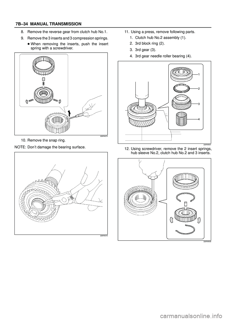
11. Using a press, remove following parts.
1. Clutch hub No.2 assembly (1).
2. 3rd block ring (2).
3. 3rd gear (3).
4. 3rd gear needle roller bearing (4).
226RW091
12. Using screwdriver, remove the 2 insert springs,
hub sleeve No.2, clutch hub No.2 and 3 inserts.
226RW090
Page 2361 of 3573

2. Using a")
MANUAL TRANSMISSION7B±43
4. Inspect hub sleeve and shift arm.
1st±2nd shift arm
1. Using a vernier caliper, measure center groove of
the 1st±2nd shift arm.
Reference: 5.28 mm (0.208 in)
2. Using a vernier caliper, measure flange of the
reverse gear. Calculate the clearance between
the reverse gear and shift arm.
Reference: Reverse gear flange thickness 5.0
mm. (0.197 in)
Standard: 0.15 ± 0.41 mm (0.006 ± 0.016 in)
226RW093
3rd±4th shift arm
1. Using a vernier caliper, measure tip of the shift
arm thickness.
Reference: 10.0mm (0.39 in)
2. Using a vernier caliper, measure center groove of
the hub sleeve No.2. Calculate the clearance
between the hub sleeve No.2 and shift arm.
Reference: Center groove dimension 10.2 mm
(0.402 in)
Standard: 0.15 ± 0.35 mm (0.006 ± 0.014 in)
226RW095
5. Inspect clutch hub and hub sleeve.
1. Check for wear or damage.
2. Install the hub sleeve to the clutch hub, and check
sliding smoothly.
226RW094
6. Inspect gear inside diameter.
1. Using a inside dial indicator, measure the gear
inside diameter.
Gear
Standard Diameter
1st46.015 ± 46.040 mm (1.8116 ± 1.8126 in)
2nd53.015 ± 53.040 mm (2.0872 ± 2.0882 in)
3rd44.015 ± 44.040 mm (1.7329 ± 1.7339 in)

Disassembled View
226RW182
Legend
(1) Snap Ring
(2) Bearing
(3) Top Gear Shaft
(4) Block Ring
(5) Roller Bearing
(6) Snap Ring
(7) Clutch Hub No.2 Assembl")
 Release Bearing and Shift Fork
(2) Clutch Housing
(3) Front Cover
(4) Snap Ring
(5) Snap Ring
(6) 1st and 2nd Switch
(7) Drain Plug
(8) Backup Light Switc")
 and gasket.
2. Remove the filler plug (2) and gasket.
(6VE1)
220RW007
2. Remove the clutch")

220RW008
5. Remove gear control box and gasket.
1. Remove the 6 bolts, gear control box and gasket.
(6VE1)")
 and a press, remove the following
parts.
1. 5th gear (1).
2. Mainshaft bearing (2).
3. 1st gear thrust washer (3).")