Page 381 of 3573
SUPPLEMENTAL RESTRAINT SYSTEM STEERING WHEEL & COLUMN 2A – 79
4
1 2
6
3
5 These steps are based on the LHD model.
Removal Steps
1. Front console assembly
2. Lower cluster assembly
3. Steering lower cover
4. Steering wheel
5. Steering column cover
6. Combination switch
Installation Steps
6. Combination switch
5. Steering column cover
4. Steering wheel
3. Steering lower cover
2. Lower cluster assembly
1. Front console assembly
REMOVAL
1. Front console assembly
1) Remove the transmission (for M/T) and transfer
control lever knob.
2) Disconnect the wiring harness connectors.
2. Lower cluster assembly
3. Steering lower cover
Remove the engine hood opening lever.
4. Steering wheel
Apply a setting mark across the steering wheel and
shaft so parts can be reassembled in their original
position.
COMBINATIONS SWITCH REPLACEMENT
431RW021
These steps are based on the LHD model.
Page 382 of 3573

2A – 80 SUPPLEMENTAL RESTRAINT SYSTEM STEERING WHEEL & COLUMN
INSTALLATION
6. Combination switch
After installations of combinations switch assembly,
connect the combination switch wiring harness
connector.
5. Steering column cover
4. Steering wheel
Align the setting marks made when removing.
CAUTION:
Never apply force to the setting wheel in direction of the
shaft by using a hammer or other impact tools in an
attempt to remove the steering wheel. The steering shaft
is designed as an energy absorbing unit.
Tighten the steering wheel fixing nut to the specified
torque.
Steering wheel Nut Torque N·m (kg·m/lb·ft)
34 (3.5 / 25)
3. Steering lower cover
Install the engine hood opening lever.
2. Lower cluster assembly
1. Front console assembly
Install the transmission (for M/T) and transfer control
lever knob.
Install the wiring harness connectors. Use special tool. Remove the steering wheel.
Move the tires to the straight ahead positions before
removing the steering wheel.
Steering wheel remover:5-8840-0016-0(J-29752)
CAUTION:
Never apply force to the steering wheel in direction of the
shaft by using a hammer or other impact tools in an
attempt to remove the steering wheel. The steering shaft
is designed as an energy absorbing unit.
5. Steering column cover
6. Combination switch
Disconnect the wiring harness connector.
Page 383 of 3573
SUPPLEMENTAL RESTRAINT SYSTEM STEERING WHEEL & COLUMN 2A – 81
These steps are based on the LHD model.
REMOVAL
1. Front console assembly
1) Remove the transmission (for M/T) and transfer
control lever knob.
2) Disconnect the wiring harness connectors.
2. Lower cluster assembly
3. Steering lower cover
Remove the engine hood opening lever.
LOCK CYLINDER REPLACEMENT
Removal Steps
1. Front console assembly
2. Lower cluster assembly
3. Steering lower cover
4. Steering wheel
5. Steering column cover
6. Combination switch
7. Snap ring
8. Cushion rubber
9. Shift lock cable (for A/T)
10. Lock cylinder assembly
Installation Steps
10. Lock cylinder assembly
9. Shift lock cable (for A/T)
8. Cushion rubber
7. Snap ring
6. Combination switch
5. Steering column cover
4. Steering wheel
3. Steering lower cover
2. Lower cluster assembly
1. Front console assembly
Page 385 of 3573
SUPPLEMENTAL RESTRAINT SYSTEM STEERING WHEEL & COLUMN 2A – 83
Tighten the steering wheel fixing nut to the specified
torque.
Steering wheel Nut Torque N·m (kg·m/lb·ft)
34 (3.5 / 25)
3. Steering lower cover
Install the engine hood opening lever.
2. Lower cluster assembly
1. Front console assembly
Connect the wiring harness connectors.
Install the transmission (for M/T) and transfer control
lever knob.
Page 387 of 3573
SUPPLEMENTAL RESTRAINT SYSTEM STEERING WHEEL & COLUMN 2A – 85
5. Steering column cover
6. Combination switch
Disconnect the wiring harness connectors.
7. Snap ring
8. Cushion rubber
9. Shift lock cable (for A/T)
10. Lock cylinder assembly
Disconnect the starter switch harness connector
located under the steering column.
11. Steering column assembly
Apply a setting mark across the universal joint and
steering shaft to reassembly the parts in their original
position.
NOTE:
A setting mark can be easily made if the shaft is
withdrawn a little by loosening the steering shaft
universal joint. 3. Steering lower cover
Remove the engine hood opening lever.
4. Steering wheel
Apply a setting mark across the steering wheel and
shaft so parts can be reassembled in their original
position.
Use special tool. Remove the steering wheel.
Move the tires to the straight ahead positions before
removing the steering wheel.
Steering wheel remover:5-8840-0016-0(J-29752)
Page 388 of 3573

2A – 86 SUPPLEMENTAL RESTRAINT SYSTEM STEERING WHEEL & COLUMN
INSTALLATION
11. Steering column assembly
Align the setting marks on the universal joint and
steering shaft made during removal.
Tighten the steering column fixing bolt (dash panel)
to the specified torque.
Steering Column Bolt Torque N·m (kg·m/lb·ft)
19 (1.9 / 14)
Tighten the steering column fixing bolt ( pedal
bracket) to the specified torque.
Steering Column Bolt Torque N·m (kg·m/lb·ft)
17 (1.7 / 13)
Tighten the universal joint to the specified torque.
Universal Joint Torque N·m (kg·m/lb·ft)
25 (2.5 / 18)
10. Lock cylinder assembly
9. Shift lock cable (for A/T)
8. Cushion rubber
7. Snap ring
6. Combination switch
After installation of combination switch assembly,
connect the combination switch wiring harness
connector.
5. Steering column cover
4. Steering wheel
Align the setting marks made when removing.
CAUTION:
Never apply force to the steering wheel in direction of the
shaft by using a hammer or other impact tools in an
attempt to remove the steering wheel. The steering shaft
is designed as an energy absorbing unit.
Tighten the steering wheel fixing nut to the specified
torque.
Steering wheel Nut Torque N·m (kg·m/lb·ft)
34 (3.5 / 25)
3. Steering lower cover
Install the engine hood opening lever.
2. Lower cluster assembly
1. Front console assembly
Connect the wiring harness connectors.
Install the transmission (for M/T) and transfer control
Page 1189 of 3573

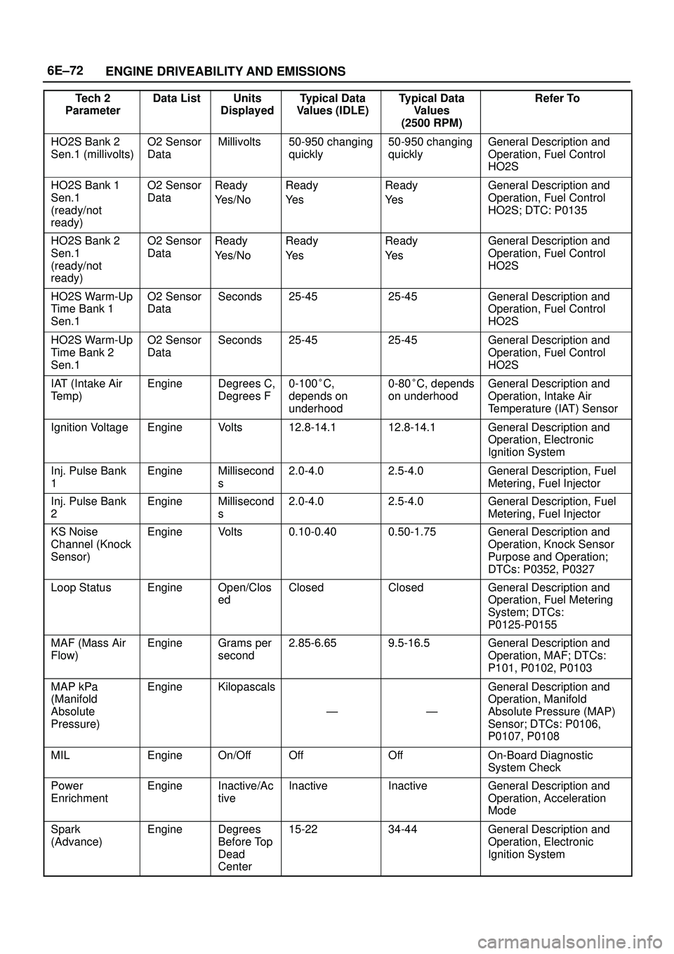
6E±72
ENGINE DRIVEABILITY AND EMISSIONS
Tech 2
ParameterRefer To Typical Data
Values
(2500 RPM) Typical Data
Values (IDLE) Units
Displayed Data List
HO2S Bank 2
Sen.1 (millivolts)O2 Sensor
DataMillivolts50-950 changing
quickly50-950 changing
quicklyGeneral Description and
Operation, Fuel Control
HO2S
HO2S Bank 1
Sen.1
(ready/not
ready)O2 Sensor
DataReady
Yes/NoReady
Ye sReady
Ye sGeneral Description and
Operation, Fuel Control
HO2S; DTC: P0135
HO2S Bank 2
Sen.1
(ready/not
ready)O2 Sensor
DataReady
Yes/NoReady
Ye sReady
Ye sGeneral Description and
Operation, Fuel Control
HO2S
HO2S Warm-Up
Time Bank 1
Sen.1O2 Sensor
DataSeconds25-4525-45General Description and
Operation, Fuel Control
HO2S
HO2S Warm-Up
Time Bank 2
Sen.1O2 Sensor
DataSeconds25-4525-45General Description and
Operation, Fuel Control
HO2S
IAT (Intake Air
Temp)EngineDegrees C,
Degrees F0-100�C,
depends on
underhood0-80�C, depends
on underhoodGeneral Description and
Operation, Intake Air
Temperature (IAT) Sensor
Ignition VoltageEngineVolts12.8-14.112.8-14.1General Description and
Operation, Electronic
Ignition System
Inj. Pulse Bank
1EngineMillisecond
s2.0-4.02.5-4.0General Description, Fuel
Metering, Fuel Injector
Inj. Pulse Bank
2EngineMillisecond
s2.0-4.02.5-4.0General Description, Fuel
Metering, Fuel Injector
KS Noise
Channel (Knock
Sensor)EngineVolts0.10-0.400.50-1.75General Description and
Operation, Knock Sensor
Purpose and Operation;
DTCs: P0352, P0327
Loop StatusEngineOpen/Clos
edClosedClosedGeneral Description and
Operation, Fuel Metering
System; DTCs:
P0125-P0155
MAF (Mass Air
Flow)EngineGrams per
second2.85-6.659.5-16.5General Description and
Operation, MAF; DTCs:
P101, P0102, P0103
MAP kPa
(Manifold
Absolute
Pressure)EngineKilopascals
ÐÐ
General Description and
Operation, Manifold
Absolute Pressure (MAP)
Sensor; DTCs: P0106,
P0107, P0108
MILEngineOn/OffOffOffOn-Board Diagnostic
System Check
Power
EnrichmentEngineInactive/Ac
tiveInactiveInactiveGeneral Description and
Operation, Acceleration
Mode
Spark
(Advance)EngineDegrees
Before Top
Dead
Center15-2234-44General Description and
Operation, Electronic
Ignition System
Page 1203 of 3573

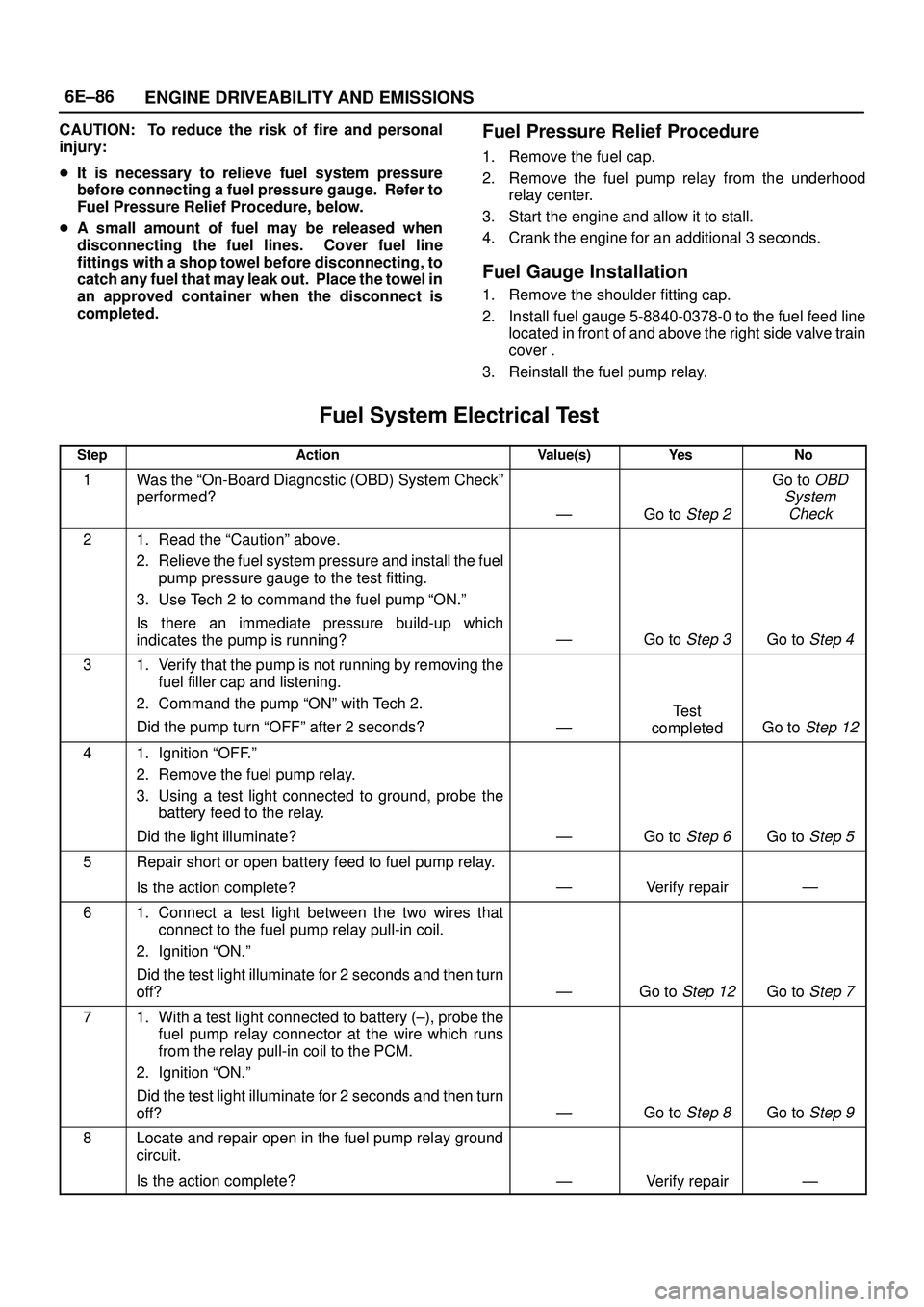
6E±86
ENGINE DRIVEABILITY AND EMISSIONS
CAUTION: To reduce the risk of fire and personal
injury:
�It is necessary to relieve fuel system pressure
before connecting a fuel pressure gauge. Refer to
Fuel Pressure Relief Procedure, below.
�A small amount of fuel may be released when
disconnecting the fuel lines. Cover fuel line
fittings with a shop towel before disconnecting, to
catch any fuel that may leak out. Place the towel in
an approved container when the disconnect is
completed.Fuel Pressure Relief Procedure
1. Remove the fuel cap.
2. Remove the fuel pump relay from the underhood
relay center.
3. Start the engine and allow it to stall.
4. Crank the engine for an additional 3 seconds.
Fuel Gauge Installation
1. Remove the shoulder fitting cap.
2. Install fuel gauge 5-8840-0378-0 to the fuel feed line
located in front of and above the right side valve train
cover .
3. Reinstall the fuel pump relay.
Fuel System Electrical Test�
StepActionValue(s)Ye sNo
1Was the ªOn-Board Diagnostic (OBD) System Checkº
performed?
ÐGo to Step 2
Go to OBD
System
Check
21. Read the ªCautionº above.
2. Relieve the fuel system pressure and install the fuel
pump pressure gauge to the test fitting.
3. Use Tech 2 to command the fuel pump ªON.º
Is there an immediate pressure build-up which
indicates the pump is running?
ÐGo to Step 3Go to Step 4
31. Verify that the pump is not running by removing the
fuel filler cap and listening.
2. Command the pump ªONº with Tech 2.
Did the pump turn ªOFFº after 2 seconds?
Ð
Test
completed
Go to Step 12
41. Ignition ªOFF.º
2. Remove the fuel pump relay.
3. Using a test light connected to ground, probe the
battery feed to the relay.
Did the light illuminate?
ÐGo to Step 6Go to Step 5
5Repair short or open battery feed to fuel pump relay.
Is the action complete?
ÐVerify repairÐ
61. Connect a test light between the two wires that
connect to the fuel pump relay pull-in coil.
2. Ignition ªON.º
Did the test light illuminate for 2 seconds and then turn
off?
ÐGo to Step 12Go to Step 7
71. With a test light connected to battery (±), probe the
fuel pump relay connector at the wire which runs
from the relay pull-in coil to the PCM.
2. Ignition ªON.º
Did the test light illuminate for 2 seconds and then turn
off?
ÐGo to Step 8Go to Step 9
8Locate and repair open in the fuel pump relay ground
circuit.
Is the action complete?
ÐVerify repairÐ