Page 1375 of 3573
6E±258
ENGINE DRIVEABILITY AND EMISSIONS
Diagnostic Trouble Code (DTC) P1625 PCM Unexpected Reset
Circuit Description
The powertrain control module (PCM) monitors
unexpected PCM reset. This will not turn on MIL light on,
only records code DTC P1625.
Conditions for Setting the DTC
�Clock or COP reset.
Action Taken When the DTC Sets
�The PCM will not illuminate the malfunction indicator
lamp (MIL).
�The PCM will store conditions which were present
when the DTC was set as Failure Records only. This
information will not be stored as Freeze Frame data.
Conditions for Clearing the MIL/DTC
�DTC P1625 can be cleared by using the Tech 2 ªClear
Infoº function or by disconnecting the PCM battery
feed.
Diagnostic Aids
Check for the following conditions:
�P1625 alone stored does not need diagnosis. Clear
DTC code.
Page 3478 of 3573

SUPPLEMENTAL RESTRAINT SYSTEM9J±41
Installation
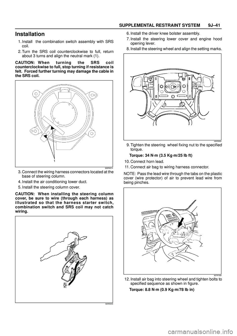
1. Install the combination switch assembly with SRS
coil.
2. Turn the SRS coil counterclockwise to full, return
about 3 turns and align the neutral mark (1).
CAUTION: W h e n t u r n i n g t h e S R S c o i l
counterclockwise to full, stop turning if resistance is
felt. Forced further turning may damage the cable in
the SRS coil.
826RW014
3. Connect the wiring harness connectors located at the
base of steering column.
4. Install the air conditioning lower duct.
5. Install the steering column cover.
CAUTION: When installing the steering column
cover, be sure to wire (through each harness) as
illustrated so that the harness starter switch,
combination switch and SRS coil may not catch
wiring.
825RS048
6. Install the driver knee bolster assembly.
7. Install the steering lower cover and engine hood
opening lever.
8. Install the steering wheel and align the setting marks.
430RS004
9. Tighten the steering wheel fixing nut to the specified
torque.
Torque: 34 N´m (3.5 Kg´m/25 Ib ft)
10. Connect horn lead.
11. Connect air bag to wiring harness connector.
NOTE: Pass the lead wire through the tabs on the plastic
cover (wire protector) of air to prevent lead wire from
being pinches.
827RT009
12. Install air bag into steering wheel and tighten bolts to
specified sequence as shown in figure.
Torque: 8.8 N´m (0.9 Kg´m/78 Ib in)
Page 3483 of 3573

SUPPLEMENTAL RESTRAINT SYSTEM 9J±46
NOTE: S R S c o i l i s a p a r t o f combination switch
assembly, which cannot be replaced separately.
Therefore, be sure not to remove the SRS coil from the
combination switch assembly.
15. Remove the snap ring.
16. Remove the cushion rubber.
17. Disconnect shift lock cable (A/T only).
18. Disconnect the starter switch harness connector
located base of steering column.
19. Remove steering lock cylinder assembly.
20. Apply a setting mark across the universal joint and
steering shaft to reassemble the parts in their original
position.
431RS013
21. Remove steering column assembly.
Installation
1. Install the steering column assembly and align the
setting marks on the universal joint and steering shaft
made during removal.
431RS013
2. Tighten the steering column fixing bolts (dash panel
side) to the specified torque.
Torque: 19 N´m (1.9 Kg´m/14 Ib ft)
3. Tighten the steering column fixing bolts (Pedal
bracket) to the specified torque.
Torque: 17 N´m (1.7 Kg´m/13 Ib ft)
4. Tighten the universal joint to the specified torque.
Torque: 25 N´m (2.6 Kg´m/18 Ib ft)
5. Install steering lock cylinder assembly.
6. Connect shift lock cable (For A/T)
7. Install cushion rubber.
8. Install snap ring.
9. Install the combination switch assembly with SRS
coil.
10. Connect the wiring harness connector located on the
base of steering column.
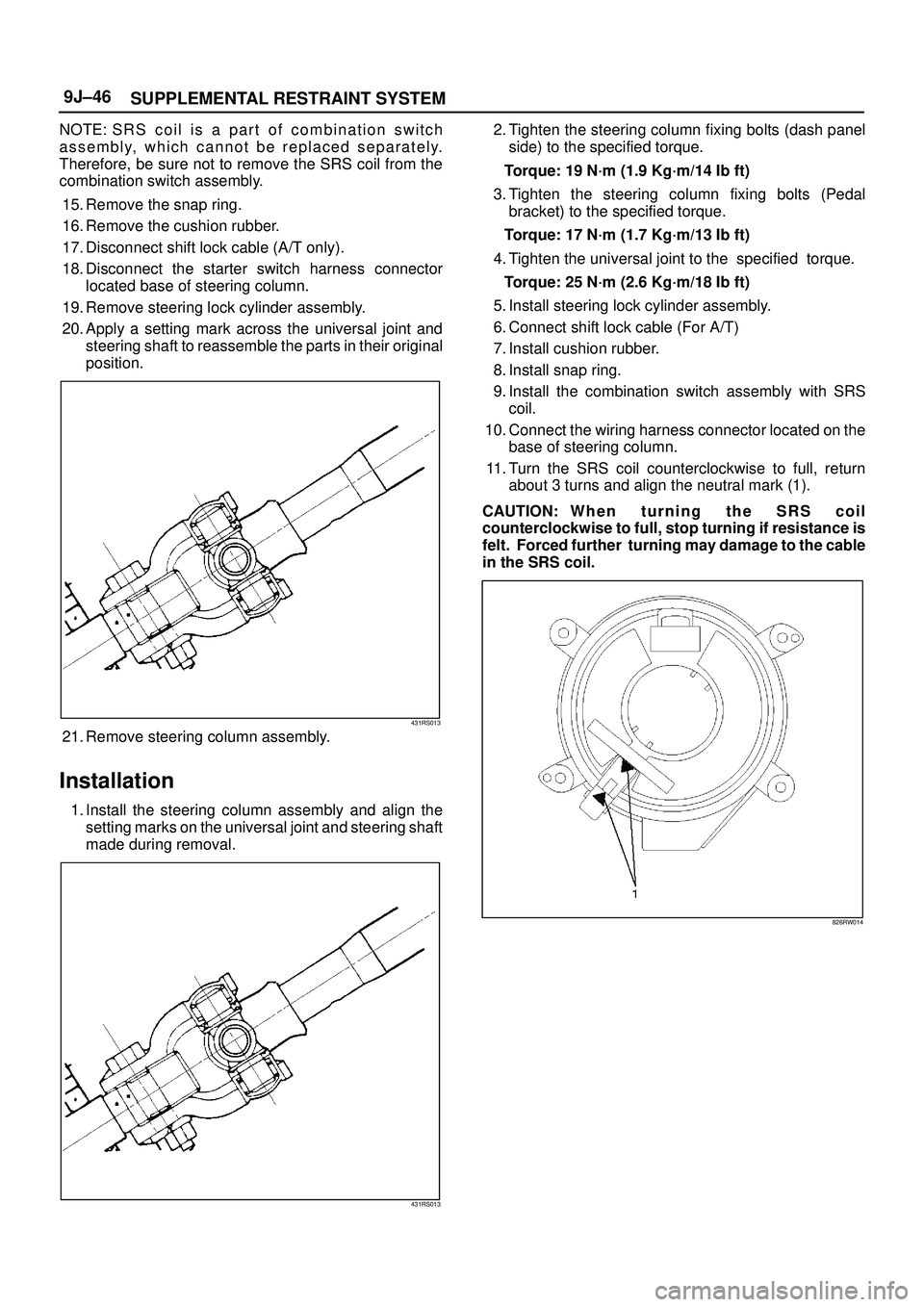
11. Turn the SRS coil counterclockwise to full, return
about 3 turns and align the neutral mark (1).
CAUTION: W h e n t u r n i n g t h e S R S c o i l
counterclockwise to full, stop turning if resistance is
felt. Forced further turning may damage to the cable
in the SRS coil.
826RW014