Page 1510 of 3573
00 Ð 10 SERVICE INFORMATION
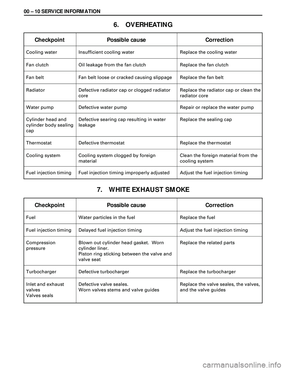
6. OVERHEATING
7. WHITE EXHAUST SMOKE
Checkpoint Possible cause Correction
Fuel Water particles in the fuel Replace the fuel
Fuel injection timing Delayed fuel injection timing Adjust the fuel injection timing
Compression
pressureBlown out cylinder head gasket. Worn
cylinder liner.
Piston ring sticking between the valve and
valve seatReplace the related parts
Turbocharger Defective turbocharger Replace the turbocharger
Inlet and exhaust
valves
Valves sealsDefective valve seales.
Worn valves stems and valve guidesReplace the valve seales, the valves,
and the valve guides
Checkpoint Possible cause Correction
Cooling water Insufficient cooling water Replace the cooling water
Fan clutch Oil leakage from the fan clutch Replace the fan clutch
Fan belt Fan belt loose or cracked causing slippage Replace the fan belt
Radiator Defective radiator cap or clogged radiator
coreReplace the radiator cap or clean the
radiator core
Water pump Defective water pump Repair or replace the water pump
Cylinder head and
cylinder body sealing
capDefective searing cap resulting in water
leakageReplace the sealing cap
Thermostat Defective thermostat Replace the thermostat
Cooling system Cooling system clogged by foreign
materialClean the foreign material from the
cooling system
Fuel injection timing Fuel injection timing improperly adjusted Adjust the fuel injection timing
Page 1520 of 3573
00 Ð 20 SERVICE INFORMATION
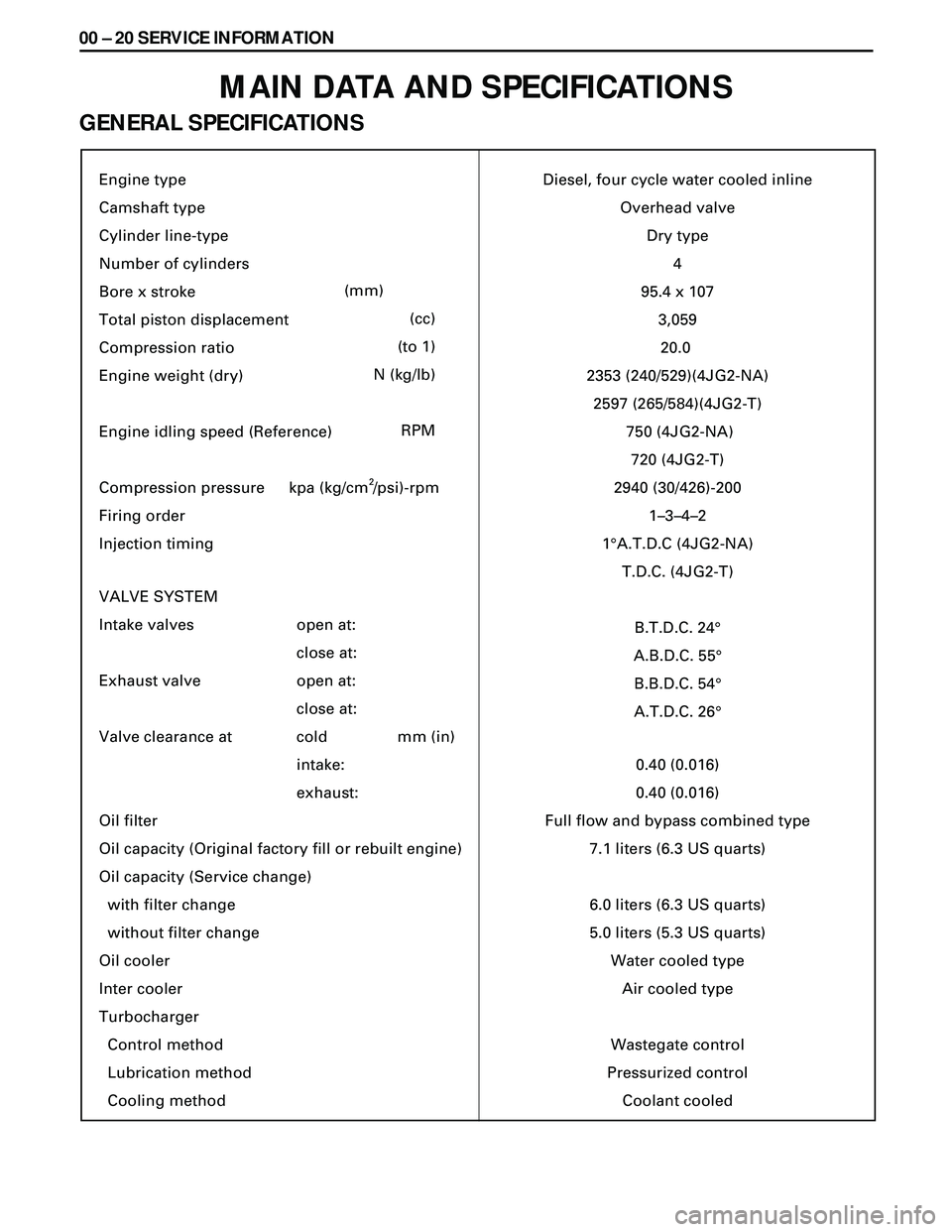
MAIN DATA AND SPECIFICATIONS
GENERAL SPECIFICATIONS
Engine type
Camshaft type
Cylinder line-type
Number of cylinders
Bore x stroke
Total piston displacement
Compression ratio
Engine weight (dry)
Engine idling speed (Reference)
Compression pressure
Firing order
Injection timing
VALVE SYSTEM
Intake valves
Exhaust valve
Valve clearance at
Oil filter
Oil capacity (Original factory fill or rebuilt engine)
Oil capacity (Service change)
with filter change
without filter change
Oil cooler
Inter cooler
Turbocharger
Control method
Lubrication method
Cooling method
(mm)
(cc)
(to 1)
N (kg/lb)
RPM
open at:
close at:
open at:
close at:
cold
intake:
exhaust:mm (in)Diesel, four cycle water cooled inline
Overhead valve
Dry type
4
95.4 x 10⁷
3,059
20.0
2353 (240/529)(4JG2-NA)
2597 (265/584)(4JG2-T)
750 (4JG2-NA)
720 (4JG2-T)
2940 (30/426)-200
1–3–4–2
1¡A.T.D.C (4JG2-NA)
T.D.C. (4JG2-T)
B.T.D.C. 24¡
A.B.D.C. 55¡
B.B.D.C. 54¡
A.T.D.C. 26¡
0.40 (0.016)
0.40 (0.016)
Full flow and bypass combined type
7.1 liters (6.3 US quarts)
6.0 liters (6.3 US quarts)
5.0 liters (5.3 US quarts)
Water cooled type
Air cooled type
Wastegate control
Pressurized control
Coolant cooled kpa (kg/cm /psi)-rpm
2
Page 1542 of 3573
00 Ð 42 SERVICE INFORMATION
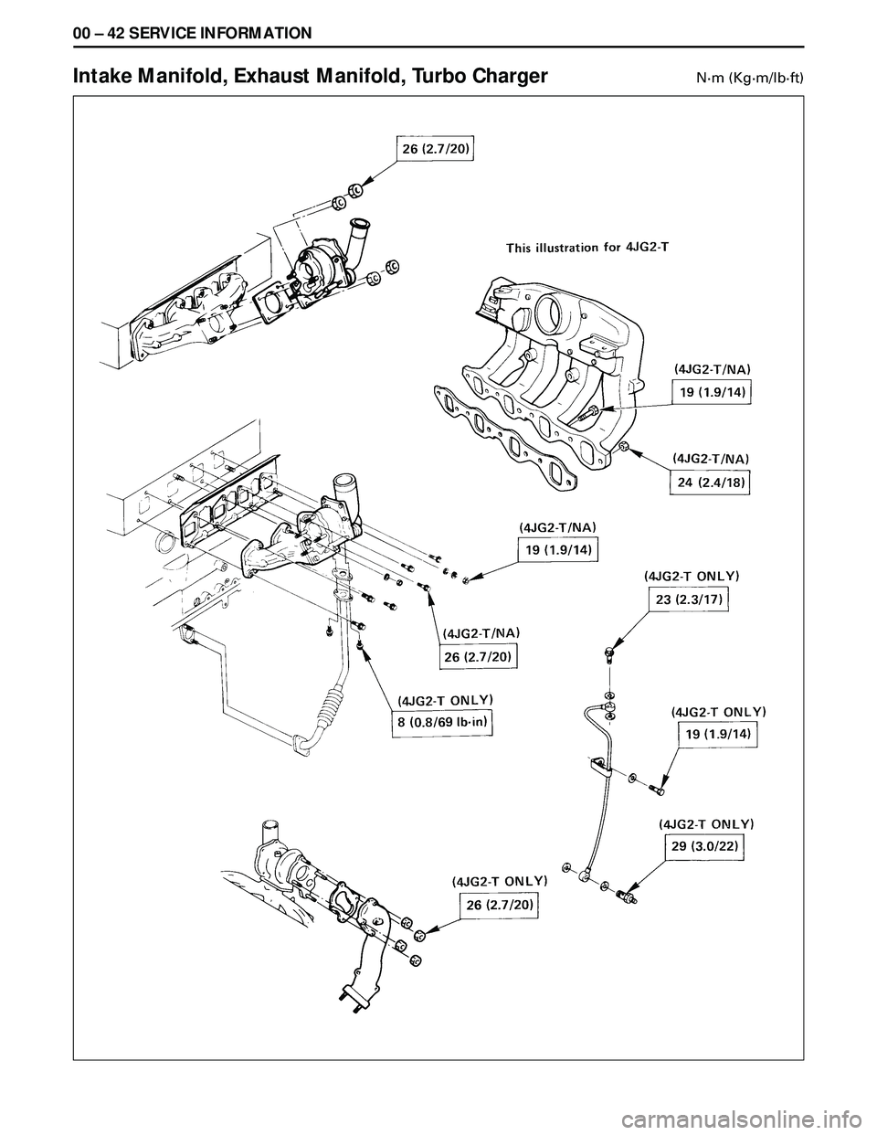
Intake Manifold, Exhaust Manifold, Turbo ChargerNám (Kgám/lbáft)
Page 1603 of 3573

4JG2-NA/4JG2-TURBO ENGINE 6A2 Ð 1
SECTION 6A2
4JG2-NA/4JG2-TURBO ENGINE
CONTENTS
PAGE
General Description ........................................................................\
............................................. 6A2- 1
Engine Mount (RH) ........................................................................\
...................................... .... 6A2- 3
Engine Mount (LH) ........................................................................\
...................................... .... 6A2- 4
Intercooler (4JG2-T only) ........................................................................\
.............................. .. 6A2- 5
Cylinder Head Cover ........................................................................\
.................................... ... 6A2- 6
Inlet Manifol d........................................................................\
........................................ .......... .6A2- 8
Exhaust Manifol d........................................................................\
...................................... ..... . 6A2-10
Turbo Charger (4JG2-T only) ........................................................................\
.......................... 6A 2-11
Timing Gear ........................................................................\
............................................ ......... 6A2-15
Valve Stem Oil Seal and Valve Spring ........................................................................\
.......... 6A2-21
Rocker Arm Shaft Assembly ........................................................................\
.......................... 6A2- 24
Cylinder Head ........................................................................\
.......................................... ........ 6A2-26
Crankcase ........................................................................\
.............................................. ........... 6A2-31
Oil Cooler ........................................................................\
............................................. ............. 6A2-34
Oil Pump Assembly ........................................................................\
...................................... ... 6A2-36
Piston, Piston Ring and Connecting Rod ........................................................................\
...... 6A2-37
Crankshaft and Main Bearing ........................................................................\
......................... 6A2 -39
Front Oil Seal ........................................................................\
......................................... .......... 6A2-45
Rear Oil Seal ........................................................................\
.......................................... .......... 6A2-46
Engine Assembly ........................................................................\
........................................ ..... 6A2-48
GENERAL DESCRIPTION
Page 1604 of 3573
6A2 Ð 2 4JG2-NA/4JG2-TURBO ENGINE
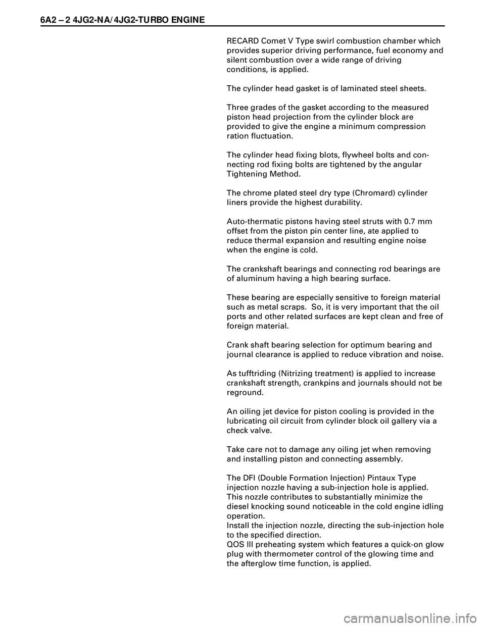
RECARD Comet V Type swirl combustion chamber which
provides superior driving performance, fuel economy and
silent combustion over a wide range of driving
conditions, is applied.
The cylinder head gasket is of laminated steel sheets.
Three grades of the gasket according to the measured
piston head projection from the cylinder block are
provided to give the engine a minimum compression
ration fluctuation.
The cylinder head fixing blots, flywheel bolts and con-
necting rod fixing bolts are tightened by the angular
Tightening Method.
The chrome plated steel dry type (Chromard) cylinder
liners provide the highest durability.
Auto-thermatic pistons having steel struts with 0.7 mm
offset from the piston pin center line, ate applied to
reduce thermal expansion and resulting engine noise
when the engine is cold.
The crankshaft bearings and connecting rod bearings are
of aluminum having a high bearing surface.
These bearing are especially sensitive to foreign material
such as metal scraps. So, it is very important that the oil
ports and other related surfaces are kept clean and free of
foreign material.
Crank shaft bearing selection for optimum bearing and
journal clearance is applied to reduce vibration and noise.
As tufftriding (Nitrizing treatment) is applied to increase
crankshaft strength, crankpins and journals should not be
reground.
An oiling jet device for piston cooling is provided in the
lubricating oil circuit from cylinder block oil gallery via a
check valve.
Take care not to damage any oiling jet when removing
and installing piston and connecting assembly.
The DFI (Double Formation Injection) Pintaux Type
injection nozzle having a sub-injection hole is applied.
This nozzle contributes to substantially minimize the
diesel knocking sound noticeable in the cold engine idling
operation.
Install the injection nozzle, directing the sub-injection hole
to the specified direction.
QOS III preheating system which features a quick-on glow
plug with thermometer control of the glowing time and
the afterglow time function, is applied.
Page 1605 of 3573
4JG2-NA/4JG2-TURBO ENGINE 6A2 Ð 3
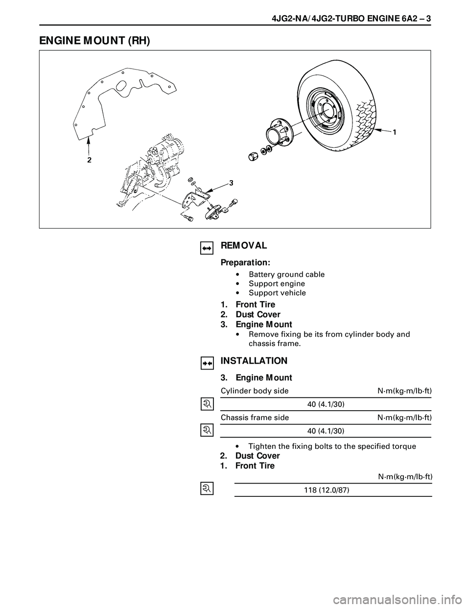
ENGINE MOUNT (RH)
REMOVAL
Preparation:
·Battery ground cable
·Support engine
·Support vehicle
1. Front Tire
2. Dust Cover
3. Engine Mount
·Remove fixing be its from cylinder body and
chassis frame.
INSTALLATION
3. Engine Mount
40 (4.1/30)
N·m(kg·m/lb·ft) Cylinder body side
40 (4.1/30)
N·m(kg·m/lb·ft) Chassis frame side
·Tighten the fixing bolts to the specified torque
2. Dust Cover
1. Front Tire
118 (12.0/87)N·m(kg·m/lb·ft)
Page 1606 of 3573
6A2 Ð 4 4JG2-NA/4JG2-TURBO ENGINE
118 (12.0/87)N·m(kg·m/lb·ft)
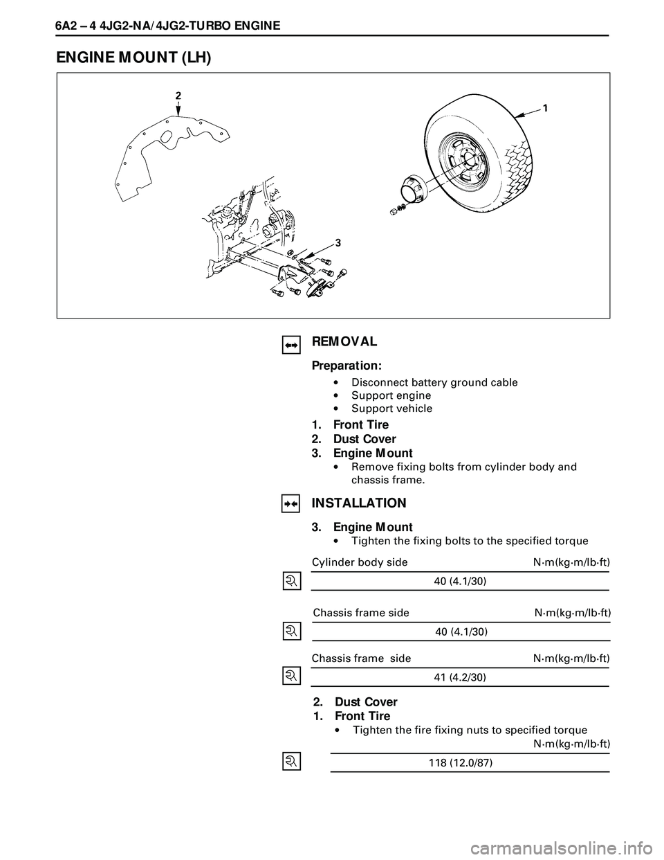
ENGINE MOUNT (LH)
REMOVAL
Preparation:
·Disconnect battery ground cable
·Support engine
·Support vehicle
1. Front Tire
2. Dust Cover
3. Engine Mount
·Remove fixing bolts from cylinder body and
chassis frame.
INSTALLATION
3. Engine Mount
·Tighten the fixing bolts to the specified torque
2. Dust Cover
1. Front Tire
·Tighten the fire fixing nuts to specified torque
40 (4.1/30)
N·m(kg·m/lb·ft) Cylinder body side
40 (4.1/30)
N·m(kg·m/lb·ft) Chassis frame side
41 (4.2/30)
N·m(kg·m/lb·ft) Chassis frame side
Page 1607 of 3573
4JG2-NA/4JG2-TURBO ENGINE 6A2 Ð 5
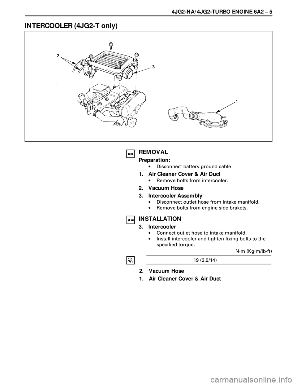
INTERCOOLER (4JG2-T only)
REMOVAL
Preparation:
·Disconnect battery ground cable
1. Air Cleaner Cover & Air Duct
·Remove bolts from intercooler.
2. Vacuum Hose
3. Intercooler Assembly
·Disconnect outlet hose from intake manifold.
·Remove bolts from engine side brakets.
INSTALLATION
3. Intercooler
·Connect outlet hose to intake manifold.
·Install intercooler and tighten fixing bolts to the
specified torque.
19 (2.0/14)N·m (Kg·m/lb·ft)
2. Vacuum Hose
1. Air Cleaner Cover & Air Duct