1998 HONDA INTEGRA cable release
[x] Cancel search: cable releasePage 36 of 1681

Lubrication Points
No. LUBRICAnON POINTSLUBRICANT
1 E^g,neAPI Service Grade: Use SJ "Energy Conserving" orSH "Energy Conserving ll" grade oil,The oil container may also display the API Certificationmark shown below. Make sure it savs "For GasolineEngines. "
SAE Viscositv: See chart below.
2TransmissionManualHonda Genuine MTF*1
AutomaticGenuine Honda Premium Formula AutomaticTransmission Fluid (ATF)*,
Brake line (lncludes Anti-lock brake line)Genuine Honda DOT3 Brake Fluid13
Clutch lineGenuine Honda DOT3 Brake Fluid*3
Power steering gearboxSteering grease P/N 08733 - 8070E
Release fork lManual transmission)Sup€r High Temp Urea Grease (P/N 08798 - 9002)
1
8
Throttle wire end (Dashboard lower oanel hole)Cruise control actuator wire end(Dashboard lower Danel hole)Silicone grease
o
10
11
14
Throttle cable end (Throttle link)Cruise control actuator cable end (Actuator link)Brake master cvlinder oushrodClutch master cylinder pushrod
Battery terminals
Fuel fill lid
Multi-purpose grease
to
17
18
Engin6 hood hinges and engine hood latchHatch hinges 8od latch or trunk hinges and latchDoor hjnges, upper and lowerDoor ooen detent
Honda White Lithium Grease
19Rear b.ake calipersSilicone grease
20Power steering systemGenuine Honda Power Steering Fluid-V or S*.
21Ai|' conditioning compressorRefrigerant oii ND-O|L8 {P/N38897 - PR7 - A01AH or38899-PR7-A01)(For Refrigerant: HFC-134a (R- 134a))
API SERVICE LABELAPI CERTIFICATION SEAL
Recommended engine oilEngin€ oil viscosity lorambrent lemperature ranges
r(For the details of lubrication points and type of lubricants to be applied, refer to the illustrated index and various work Dro-cedure (such as Assembly/Reassembly, Replacement, Overhaul, Installation. etc.) contained in each section,
*1: Always use Genuine Honda Manual Transmission Fluid (MTF). Using motor oil can cause stiffer shifting because itdoes not contain the proper addtuves.*2: Always use Genuine Honda Premium Formula Automatic Transmission Fluid (ATF). Using a non-Honda ATF can affectshift quality.*3: Always use Genuine Honda DOT 3 B.ake Fluid, Using a non-Honda brake fluid can cause corrosion and decrease thelife of the system.'4: Always use Genuine Honda Power Steering Fluid-V or S. Using any other type of power steering fluid or automatictransmission fluid can cause increase v,/ear and poor steering in cold weather.
L(
{
4-2
Page 323 of 1681

The fuel supply system co
high pressure fuel pump, t
fuel pressure regulator. f
damper, and fuel delivery i
delivers pressure-regulated
cuts the luel delivery when
Fuel Supply System
System Description
consists of a fuel tank, in-tank
r, PGM-Fl main relay, fueffilter,
. fuel injectors, fuel pulsation
y and return lines. This system
ed fuel to the fuel injectors and
rn thq engine is not running.
Fuel Pressure
Relieving
Before disconnecting fuel pipes or hoses, release pres-
sure from the system by loosening the 12 mm banjo
bolt on top ol the fuel filter.
Do not smok€ while working on the tuel system,
Keep open flames or sparks away from you. work
arga.
Be sure to relieve fuel pressure while the ignition
swiich is ofl,
Make sure you have the anti theft code for the
radio, then write down the frequencies for the
radio's preset buttons.
Disconnect the battery negative cable from the bat-
tery negative terminal.
Remove the fuelfill cap.
Use a box end wrench on the 12 mm banjo bolt at
the fuel filter while holding the fuel filter with another
wrench.
Place a rag or shop towel over the '12 mm banjo
bolt.
Slowly loosen the 12 mm banjo bolt one complete
tu rn.
1 1-1 18
I
NOTE| Replace the washers whenever the 12 mm banjo
bolt is loosened or removed.
lnsDection
1. Relieve fuel pressure.
2. Remove the 12 mm banjo bolt from the fuel filter
while holding the fuel tilter with another wrench.
Attach the fuel pressure adapter bolt, 12 mm and
the special tool.
3. Stan the engine. Measure the tuel pressure with the
engine idling and the vacuum hose of the fuel pres-
sure regulator disconnected from the fuel pressure
regulator and pinched. lf the engine will not start,
turn the ignition switch ON (ll), wait for two sec-
onds, turn it off, then back on again and read the
tuel pressure.
Pressuro should be:
Bl8Bl engire:
270 - 320 kP. (2.8 - 3.3 kgl/cm'.40 - 47 psi)
818C1, 818C5 engines:
320 - 370 kPa (3.3 - 3.8 kgt/cm'. 47 - g psi)
12 mm
FUEL FILTER
Page 335 of 1681
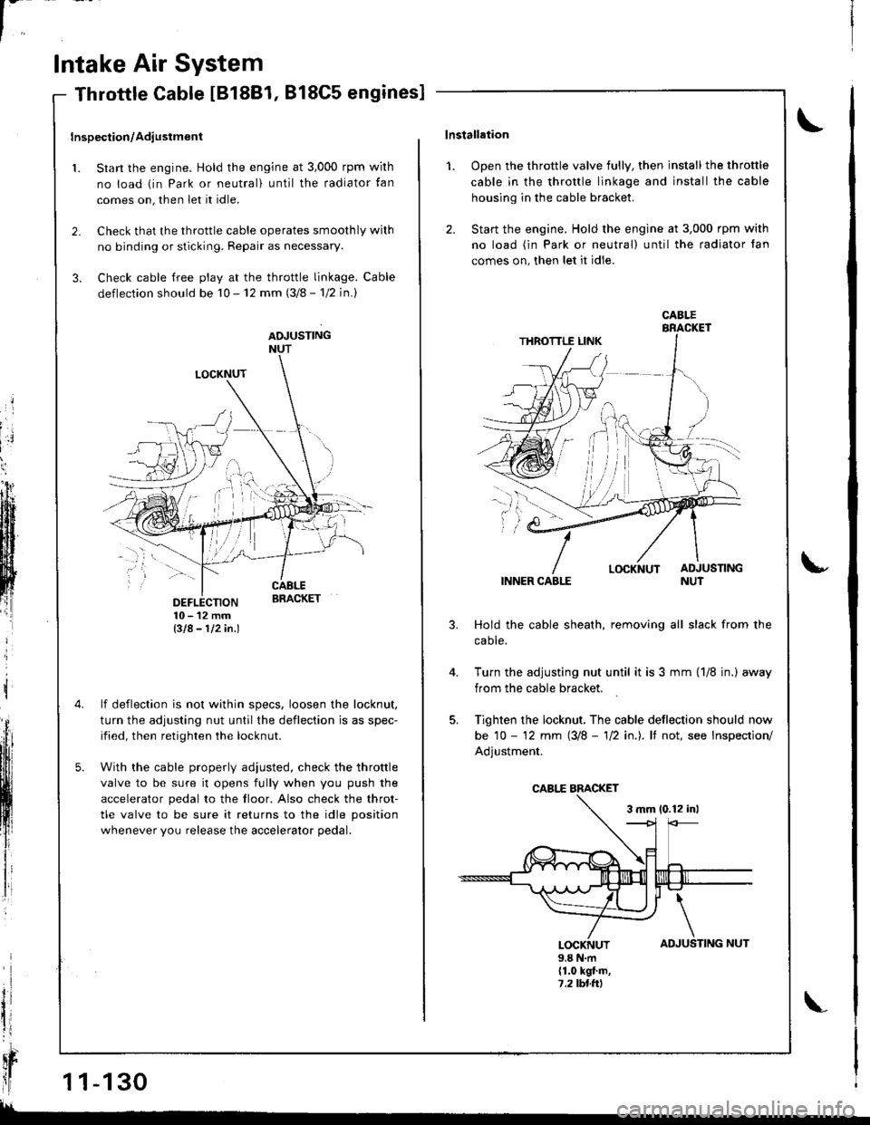
l-
Intake Air System
LOCKNUT
DEFLECTION10-12mmBIA- 112in.l
lf deflection is not within specs, loosen the locknut,
turn the adjusting nut until the deflection is as spec-
ified, then retighten the locknut.
With the cable properly adiusted, check the throttle
valve to be sure it opens fully when you push the
accelerator pedal to the floor. Also check the throt-
tle valve to be sure it returns to the idle position
whenever you release the accelerator pedal.
Throttle Cable IB18B1, 818C5 engines]
Inspection/Adiustment
1. Start the engine. Hold the engine at 3,000 rpm wirh
no load (in Park or neutral) until the radiator tan
comes on, then let it idle.
2. Check that the throttle cable operates smoothly wilh
no binding or sticking. Repair as necessary.
3. Check cable free play at the throttle linkage. Cable
deflection should be 10 - 12 mm (3/8 - 'l12 in.l
ADJUSTINGNUT
t
il
qr
ll1 1-130
!!
TING NUT
\lnstallation
1. Open the throttle valve fully, then install the throttle
cable in the throttle linkage and install the cable
housing in the cable bracket.
2. Start the engine. Hold the engine at 3,000 rpm with
no load (in Park or neutral) until the radiator fan
comes on, then let it idle.
INNER CABLE
Hold the cable sheath, removing all slack from the
caote.
Turn the adjusting nut until it is 3 mm {1/8 jn.) away
from the cable bracket.
Tighten the locknut, The cable deflection should now
be 10 - '12 mm (3/8 - 'll2 in.). lf not, see Inspection/
Adjustment.
3 mm 10.12 inl
u
4.
AD
\
JUSLOCKNUT9.8 N.m(1.0 kgt.m,7,2lbl.ttl
CABI.E
CABI,E BMCKET
Page 336 of 1681
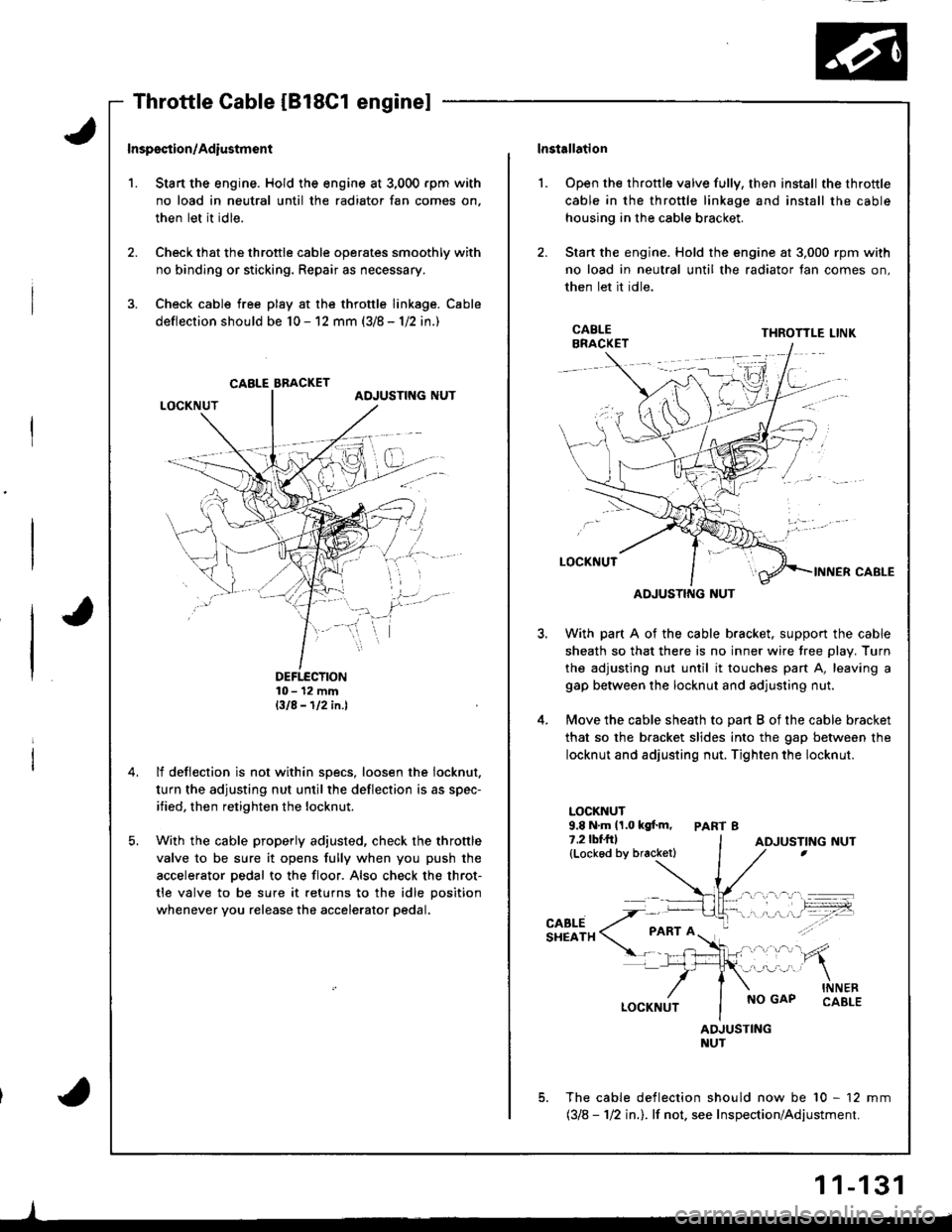
't.
Inspsction/Adiustmsnt
Stan the engine. Hold the engine at 3,000 rpm with
no load in neutral until the radiator fan comes on,
then let it idle.
Check that the throttle cable operates smoothly with
no binding or sticking. Repair as necessary.
Check cable free play at the throttle linkage. Cable
deflection should be 10 - 12 mm (3/8 - 1/2 in.)
DEFTECTION10- 12 mmBIA-112in.l
lf deflection is not within specs, loosen the iocknut.
turn the adjusting nut until the deflection is as spec-
ified, then retighten the locknut.
With the cable properly adjusted, check the throttle
valve to be sure it opens fully when you push the
accelerator pedal to the floor. Also check the throt-
tle valve to be sure it returns to the idle position
whenever you release the accelerator pedal.
CABLE BBACKET
lnstallation
Open the throttle valve fully, then install the throttle
cable in the throttle linkage and install the cable
housing in the cable bracket.
Stan the engine. Hold the engine at 3,000 rpm with
no load in neutral until the radiator fan comes on,
then let it idle.
l.
3.
5.
CABLEBRACKETTHROTTLE LINK
ADJUSTING NUT
With part A of the cable bracket. support the cable
sheath so that there is no inner wire tree plav. Turn
the adjusting nut until it touches part A, leaving a
gap between the locknut and adjusting nut.
Move the cable sheath to oart B of the cable bracket
that so the bracket slides into the gap between the
locknut and adjusting nut. Tighten the locknut.
LOCKNUT9.8 N.m 11.0 kgf.m, PART 87.2lbf.frl(Lockod by bracketl
CABLESHEATH
NO GAPINNERCABLE
ADJUSTINGNUT
The cable deflection should now be 10 - 12 mm(318 - 112 in.l. lf not. see Inspection/Adjustment.
ADJUSTING NUT
1 1-131
Page 518 of 1681

\a
t
Clutch LoWHigh Prossuro Moasursment
@ wnire t6sting, be carelul of the rotating
front whaols.
- 1. Allow the front wheels to rotate freelv.
2. Remove the cable end of the throttle control cable
trom the throttle control drum.
NOTE: Do not loosen the locknuts, simply unhook
the cable end.
THROTTLE CONTROL DRUM
-3. Start the engine and let it idle.
-4. Shitt to @ position.
5. Slowly move the throttle linkage to increase engine
rpm until pressure is indicated on the A/T pressure
gauge.
Then release the throttle linkage, allowing the en-
gine to return to an idle, and measure the pressure
reading.
6. With the engine idling. lift the throttle controldrum
up approximately 'l12 of its possible travel and in-
crease the engine rpm until pressure is indicated
on the gauge, then measure the highest pressure
reading obtained.
- 7. Repeat steps 5 and 6 for each clutch pressure be-
ing inspected.
d
Q^--,'.-
THROTTLE CONTROL DRUM
(conr'd)
14-101
Page 592 of 1681

Adiustment
CAUTION:
a All SRS wile harnesses are covered with yellow insu-
lation. Belore you disconnect any part ol an SRS wire
harness, disconnect the akbag connectors'
a Whenever the ignition switch is ON (ll), or has been
tumed OFF tol less than three minutes, be caletul not
to bump the SRS unit; the airbags could accidentally
deploy and cause damage or injuries'
a For additionalprecautions, referto the SRS sub-section
SBS MAIN HARNESS(Covered with yellow inslrlationl
$!@ rtl"t . "ure lifts are placed plope y lsee sec-
tion 1 l.
'1. Remove the center console lsee section 20)'
2. Snitt to $ position, then remove the lock pin lrom
the cable adjuster'
LOCKNUT7 N.m10.7 kgf.m, 5 lbf.fl)
t
]H
@
@
@
{l
LOCK PIN
14-176
shift cable
3. Check that the hole in the adjuster is perfectly
sligned with the hole in the shift cable'
CableToo Short
NOTE: There are two holes in the adjuster. They are
positioned 9Oo apart to allow cable adiustment in 1/4
turn Incremenrs.
4. lJ the hole is not per{ectly aligned, loosen the locknut
on the adjuster, and adiust as required.
5. Tighten the locknut to 7 N'm (0.7 kgf'm, 5lbf'ftl
6. Installthe lock pin on the adiuster. lI you feelthe lock
pin binding as Vou reinstall it, the cable is still out ot
adjustment and must be readjusted.
7. [/ake sure the lock pin is seated securely in the
aoJusrer.
8. Move the shift lever to each gear, and verify that the
automatic transaxle gear position indicator follows the
automatic transaxle gear position swatch.
9. Start the engine, and check the shift lever in allgears'
lf any gear does not work properly, refer to
troubleshooting on page 14-90 thru 93.
10. Insert the ignition key into the key cylinder on the shift
indicator panel, verify that the shift lock lever is
released.
CableToo Long
ExactAlignment
\
ADJUSTER
Page 673 of 1681
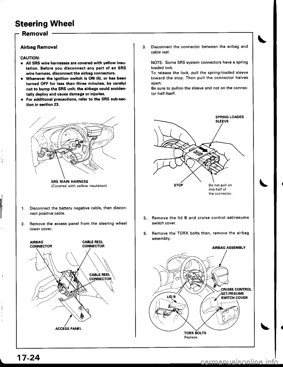
Steering Wheel
Removal
Airbag Removal
'CAUTION:
. All SRS wiro harne33e3 ar€ coverad with yellow insu.
lation. Beforo you di3connect Eny part of En SRS
wiro harn6ss, disconnsct the airbag conncctors.
. Whenaver ths ignition switch is ON {ll}, or ha3 b.cn
turned OFF lor l.3s than thrcc minuto3, be cErs{ul
not to bump th6 SRS unh; the airbags could rcciden-
tally deploy and cause damsgo or iniurias'
. Fo. additional preclution3, rofer to tho SRS sub-soc'
tion in 36ction 23,
Disconnect the battery negative cable, then discon-
nect Dositive cable.
Remove the access panel from the steering wheel
lower cover.
CABLE REEL
L
SRS MAIN HARNESS
17-24
Disconnect the connector between the airbag and
cable reel.
NOTE: Some SRS system connectors have a spring
loaded lock.
To release the lock, pull the spring-loaded sleeve
toward the stop. Then pull the connector halves
apart.
Be sure to pullon the sleeve and not on the connec-
tor half itself.
Remove the lid B and cruise control set/resume
switch cover.
Bemove the TORX bolts then, remove the airbag
assembly.
SPRING.LOADED
AIRBAG ASSEMBLY
Page 676 of 1681

Installthe airbag assembly with new Torx bolts, and
installthe covers.
cRursECONTROLSET/RESUMEswtTcH covER
Hold the pawl side connector half. and press on the
back of the sleeve-side connector halt in the direction
shown. As the two connector halves are pressed
together, the sleeve is pushed back by the pawl.
NOTE: Do not touch the sleeve.
7.When the connector halves are completely connected.
the pawl is released. and the spring loaded sleeve
locks the connector.
SPRING.LOADEDSLEEVE
Attach the connector in the holder, then install the
access panel on the stee.ing wheel lower cover.
Connect the positive cable first. then the negative
cable to the battery.
After installing the airbag assembly, confirm proper
system operation:
. Turn the ignition switch ON (ll); the instrument
panel SRS indicator light should come on for
about six seconds and then go off.
. Confirm operation of horn buttons.
. Confirm operation of cruise control sevresume
switches.
10.
17-27