Page 1212 of 1681

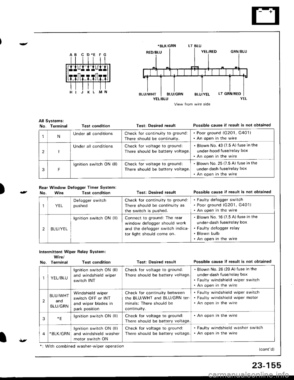
A B C D *E F G
YEL/BLU
View from wire side
All Systems:
No. TerminalTest condition
Rear Window Defogger Timel System:
No. WireTest condition
Test: Desired resultPossible cause if result is not obtained
Test: Desired resultPossible cause it lesult is not obtained
Test: Desired resultPossible cause if result is not obtained
(cont'd)
)
Inte.mittent Wiper Relay System:
Wire/
No. TerminalTest condition
*BLK/GRN
1NUnder all conditionsCheck for continuity to ground:
There should be continuity.
. Poor ground (G201, G401). An open in the wire
2
Under all conditionsCheck Jor voltage to groundl
There should be battery voltage
. Blown No. 43 (7.5 A) fuse in the
under hood fuse/relay box
'An open in the wire
3F
lgnition switch ON (ll)Check for voltage to ground:
There should be battery voltage.
. Blown No. 25 (7.5 A) fuse in the
under dash fuse/relay box
. An open in the wire
1YEL
Delogger switch
pusneo
Check for continuity to ground:
There should be continuity as
the switch is pushed.
Faulty defogger switch
Poor ground (G201, G401 )
An open in the wire
2BLU/YEL
lgnition switch ON (ll)Connect to groundr The rear
window defogger should work
and the defogger switch indica
tor light should come on.
Blown No. 16 (7.5 A) fuse in the
under-dash fuse/relay box
Faulty delogger relay
Blown bulb
An open in the wire
YEL/BLU
lgnition switch ON (ll)
and windshield wiper
switch INT
Check lor voltage to ground:
There should be battery voltage
Blown No.26 (20 Ai fuse in the
under-dash fuse/relay box
Faulty windshield wiper switch
An open in the wire
2
BLU/WHT
and
BLU/GRN
Windshield wiper
switch OFF or INT
and wiper blades in
park position
Check for continuity between
the BLU/WHT and BLU/GRN ter
minals: There should be
contrnurty.
Faulty windshield wiper switch
Faulty windshield wiper motor
An open in the wire
3lgnition switch ON (ll)Check lor voltage to ground:
There should be battery voltage
An open in the wire
*BLK/GRNlgnition switch ON (ll)
and windshield washer
motor switch ON
Check lor voltage to ground:
There should be battery voltage.
Faulty windshield washer switch
An open in the ware
v*: With combined washer-wiper oDeration
23-155
Page 1235 of 1681
Dash Lights Brightness Control
Circuit Diagram
UNDER-HOOO FUSgRELAY 8OXUNDEN.DASHFUSE/RELAYEOXtX"f -.------^-;^*;;ilLrcrTswrc.
ffiwHT-lf-FEDGaN
, &TGEAN POSITION INOICATOROIMMING CIFCUIT.ATTGEAB POSITION CONSOLE LIGHT
. CRUISE COI,{TROL DIMMING CIRCUIT.CRUISE CONTHOT MAIN SWITCH LIGHT.GAUGE LIGHTS.HAZAFDWABN NG SWITCH LIGHT. HEATER CONTROL PANEL LIGHTS. REAR WINDOW DEFOGGER SWITCH LIGHT
23-178
Page 1248 of 1681
High Mount Brake Light Replacement (Bulb type)
Hatchback:Sedan:
1.Open the hatch.
Remove the two clips and the cover.
Remove the two nuts and the high mount brakelight, then disconnect the 2P connecror.
1.Open the trunk lid, and disconnect the 2P connector
from the high mount brake light.
Remove the two nuts, then remove the high mount
brake light from the rear shelt.
2.
3.
2.
2P CONNECTOR
Turn the socket 45o counterclockwise to remove the
bulb.
Install the high mount brake light in the reverse or-
der of removal, and clean the rear window glass be-
tore installing.
CAUTION: When installing the high mount brake
light, make sure the rubber seal fits against the reai
window evenly.
3.Install the high mount brake light in the reverse or
der of removal. Clean the rear window qlass belore
installing the light.
5.
)
23-191
Page 1271 of 1681
Rear Window Defogger
Component Location Index
Description
The rear window de{ogger is controlled by the integrated control unit. Pushing the detogger switch in the Instrumentpanel sends a signal to the defogger timer in the integrated control unit, and the defogger stays on for 25 minutes oruntil the ignition switch is turned off. The indicator light in the switch comes on when the defogger works.
UNDER.OASH FUSE/RELAY BOX
r-'luijij u lNEAR WINDOWDEFOGGER SWITCHRemoval, page 23-217Test, page 23 217
REARDEFOGGERREI-AYTest, page 23-69
23-214
Page 1272 of 1681
Circuit Diagram
REARwtNDowDEFOGGERSWITCH
BLK
IIJ
DASH LIGHTSBR CHTNESSCONTROLLER
CN TIONswrTcH
/ 8AT \
T ",7-l
II
II
WNT/BLK + WHT
REARWiNDOWDEFOGGER
BtK/GRN
--lELKGRN BLI(RED
1A
T L-]
ll
tl
tl
tl-l
UNDEF HOOD FUSE/RELAY BOX
No41 (100A) N0.42 (40A)
G201G401G201G40lHatchback:G771Sedan iG503I
23-215
Page 1273 of 1681
Rear Window Defogger
Troubleshooting
NOTEr The numbers in the table show the troubleshootino seouence
Item to be inspected
Symptom
=
o
.9
.E
;
ao
o
s
;!i6
<:
FO
>=
;€9c
';i !
oi
O=
{o
a5
3tr
ta
fu-o
,
OJo)
o
c
'-c
Defogger works, but indicator
light does not go on.BLK/YEL or BLU/YEL
Defogger does not work and
indicator light does not go on.3G201
G401YEL, BLU/YEL or BLK/YEL
Defogger does not work, but
indicator light goes on.123G7 71
G503
BLU/YEL or BLK/YEL
BLK/GRN or BLK/WHT
Operation time is too long or
too short (normal operation time
is 25 minutes).
,]
23-216
Page 1274 of 1681
)
Switch Removal
CAUTION: Be carelul not to damage the heater con-
trol/center air vent.
1. Carefully pry the switch out oI the heater con-
trol/center air vent.
2. Disconnect the 6P connector from the switch.
Remove the indicator bulb (turn the socket 45o
counterclockwise), and remove the illumination bulb.
REAR WINDOWDEFOGGER SWITCH
INDICATOR BULB(o.84 W)
.l
Switch Test
NOTE: Be careful not to damage the heater con-
trol/center air vent.
'1. Carefully pry the switch out of the heater con-
trol/center air vent.
2. Check tor continuity between the terminals accord
ing to the table.
Terminal
pLN-_\BcDEF
PUSHEDo/:\-oo--o
o-
\:./
-o\:/
RELEASEDo-/:\_o
-oo-
\:,/
/:\\:./
I
6P CONNECTOR
REAR WINDOW DEFOGGER SWITCH
23-217
Page 1275 of 1681

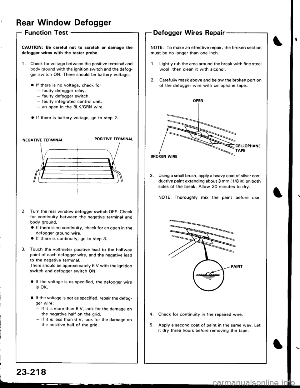
Rear Window Defogger
Function TestDefogger Wires Repair
I
I
CAUTION: Be caretul not to scratch or damage the
defogger wires with the tester probe,
1. Check tor voltage between the positive terminal and
body ground with the ignition switch and the defog-
ger switch ON. There should be battery voltage.
lf there is no voltage, check for
faulty defogger relay.- faulty defogger switch.- faulty integrated control unit.- an open in the BLK/GRN wire.
lf there is battery voltage, go to step 2.
NEGATIVE TERMINALPOSITIVE TEFMINAL
2.Turn the rear window defogger switch OFF. Check
for continuity between the negative terminal and
body ground.
a lf there is no continuity, check for an open in the
defogger ground wire.a lf there is continuity, go to step 3.
Touch the voltmeter positive lead to the halfwaypoint of each delogger wire, and the negative lead
to the negative terminal.
There should be approximately 6 V with the ignition
switch and defogger switch ON,
a lf the voltage is as specified, the defogger wire
is OK.
a lf the voltage is not as specified, repair the defog-ger wire:
lf it is more than 6 V, look for the damage on
the negative half on the grid.
lf it is less than 6 V, look for the damage onthe positive half of rhe grid.
3.
NOTE: To make an elfective repair, the broken section
must be no longer than one inch.
1 . Lightly rub the area around the break with fine steel
wool, then clean it with alcohol.
2. Carefully mask above and below the broken portion
of the defogger wire with cellophane tape.
CELLOPHANETAPE
BBOKEN WIRE
3, Using a small brush, apply a heavy coat of silver con-
ductive paint extending about 3 mm (l /8 in) on both
sides of the break. Allow 30 minutes to dry.
NOTE: Thoroughly mix the paint before use.
Check for continuity in the repaired wire.
Apply a second coat of paint in the same way.
it dry three hours before removing the tape.
Let
OPEN
23-214