1998 HONDA INTEGRA parking brake
[x] Cancel search: parking brakePage 1427 of 1681
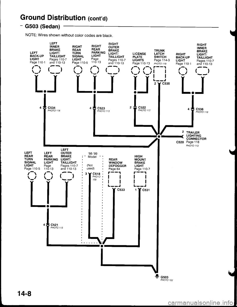
Ground Distributioh (cont'd)
- G503 (Sedan)
NOTE: Wkes shown without color codes are black.
LEFTIN NERBRAKELEFT LIGHT/BACK-UP TAILLIGHTLIGHT Paqes 110-7Paqe 110,1 and 110-13
r-,r ,--r\_,, r- -,
c534
L.JLIJL.J
TRAILERLIGHTINGCONNECTORPage 118
RIGHTINNERBRAKELIGHT/TAILLIGHTPages 110-7and 110-13
()
RrcHr l!-c.{r !'rqlt-
!iTfi^. iff#"" iilt[i",
b:::1,0. ii3:3 :i3::lts'
(:) (:) rllr
TRUNKLATCHswtTcHPage 114-3
tl
tl
2 Y C535
RIGHTBACK-UPLIGHTPage 110 1
/\
LEFTREARTURNSIGNALLIGHTPage 110-5
LEFTREARPARKINGLIGHTPage110-13
/\
LEFTOUTERBRAKELIGHT/TAILLIGHTPages 1'10-7and 110-13
()
'98-'�99
Model
(Notuseo)
cs22
HIGHMOUNTBRAKELIGHTPage 110-7
tl
REARwrNDowDEFOGGERPage 64
ll
14-8
Page 1488 of 1681
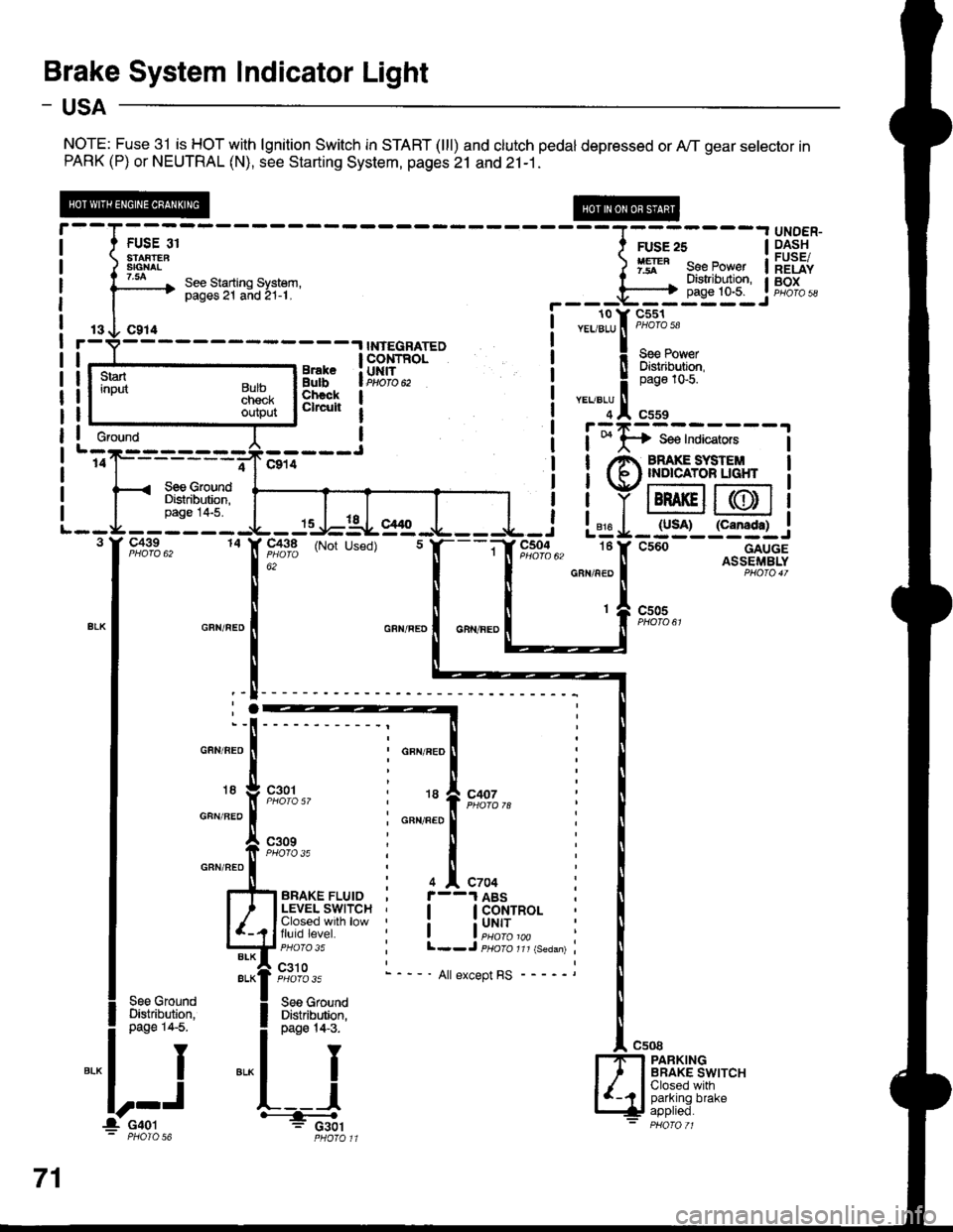
Brake System Indicator Light
- USA
NOTE: Fuse 31 is HOT with lgnition Switch in START (lll) and clutch pedal depressed or A,/T gear selector inPARK (P) or NEUTRAL (N), see Starting System, pages 21 and 21-1.
13 O C914r-V----- -.l INTEGRATED
!r--_.ts__rr,"*" !ERT'"o. | lBtr,i{,fr;
Lj':e--:---J I i;I;:;*;;.;
'of------;-Jclil ! !/e ffiS,'#LT",l< see crouno I I Vr:-:--t r--:=:
ilrF'fi$l ffiiiY@@
-3:".J:iTIS:
I T..T I
Il
! ! YIBRAKEII(DI1
- - - - - - -{L - Js-J=-AL- g1g -.1- - - -{- - i L"jg I _ lyso)_ l"g:f.l_..1
F,o:fo", to IF,flt'3 (Not used) t f,---if r",*%u, tef csoo---.--^g+.rSS
r--T- --- ----r UNDER-
I t FUSE or I ruse zs | 9.4.s!t
i ) 3ffi8" ) 1ry" eeeJo"", ilEiiv
i l3--* ::3"Tii'lH.'ti:i' r il"'li$lr if,g[;,
I | !---r-o v-cl6r-
----.,NrEGRArED i
""lltrt:1'
3ni"iFfi,t-- i !Flif{#r
3i}fi[ | i
"':lln*
, I r:zr=---
*"*'l
.:.:,*,
L--g--3 I' C439
15 -l-lal- el/ t
14 X 91^3,q (Not Used)
; : 816 | IUJA' {LaI|Agtt .J L=g-:__i_-:J
"; " I ll -"," - ll AsslFrr,rBLYGRN/NED I PHO|O4T
c505
GFN/BEO
18
GFN/BEO
GRN/NEO
GFN/FED
18
GFN/FED
I
I
'-l
;.
t
;"x
c301
c309PHOfO 35
c407
4 ^ C704
I GoNTROL
i uNrr
l--J psoro rrr {seaan)
- ' All except RS
See GroundDi$tribution,page 14-5.
PARKINGBRAKE SWITCHClosed withparking brake
Gfound
71
l_ c4ol' PHOIO 56
Page 1522 of 1681
![HONDA INTEGRA 1998 4.G Workshop Manual - Canada Only
UNDER-OASHFUSE/RELAYBOX
T@-];----
_ti:___:_c440
;
J
j
r-----
I See Power: Distribution,I page 10-8.
I
IL-----
FUSE 20{FUNNING LIGHTS)
See BrakeSystemIndicalor Light
c439
c41sc416
c416
ar HONDA INTEGRA 1998 4.G Workshop Manual - Canada Only
UNDER-OASHFUSE/RELAYBOX
T@-];----
_ti:___:_c440
;
J
j
r-----
I See Power: Distribution,I page 10-8.
I
IL-----
FUSE 20{FUNNING LIGHTS)
See BrakeSystemIndicalor Light
c439
c41sc416
c416
ar](/manual-img/13/6069/w960_6069-1521.png)
- Canada Only
UNDER-OASHFUSE/RELAYBOX
T@-];----
_ti:___:_c440
;
J
j
r-----
I See Power: Distribution,I page 10-8.
I
IL-----
FUSE 20{FUNNING LIGHTS)
See BrakeSystemIndicalor Light
c439
c41sc416
c416
arr<
DAYTIMERUNNINGLIGHTSCONTROLUNIT
c302
1
WHT/NEO
WHT/FEO
DAYTIMERUNNINGLIGHTSRESISTOR
c307c440
.I UNDER.DASHI FUSE/RELAYI 8OXI Pqofa 53
c504
18
r
I
I
1
A C508
l-l-l PARKINGI ' I BRAKE| .( | swrrcH| ..- t I Closed with4 parking brake- applreo.PHAfO 71
c301
See GroundDistribution,page 14-4.
Y
I
I
a:."-
Lights-on Batteryinpul
Headlight control
lgnitionBrake system indicatorlight control
GroundParking brake input
r-910-1-
1 10-9
Page 1523 of 1681
Headlights (cont'd)
- How the Circuit Works
Low Beam OperationRefer to the Service Manual (Section 23, Electrical)
for specific tests or troubleshooting procedures.
With the headlight switch in HEAD and the dimmer
switch in LO, current flows through the headlight
switch, fuse 21 , tuse 22, and the low beam
filaments to ground, and the low beams come on.
tligh Beam Operation
With the headlight switch in HEAD and the dimmer
switch in Hl, current flows through the headlight
switch, dimmer/passing switch, fuses 4, 5, 21, and
22, and the low and high beam filaments to ground,
and the low and high beams come on.
Current also tlows through the high beam indicator
light to ground. The high beam indicator comes on
to remind the driver that the high beams are on.
Flash operation
The flash feature works with the headlight switch in
OFF, PARK, or HEAD (low beams). When you
move the flash-to-pass switch to ON, current flows
through the switch, fuses 4 and 5, and the high
beam filaments to ground, and the high beams
flash. The high beam indicator also flashes during
the flash oDeration. The flash function has no effect
it the high beams are already on.
Daytime Running Lights Day Operation
When you turn the ignition to ON (ll) with the
parking brake released, the daytime running lights
control unit supplies battery voltage at the
WHT/RED wire. This voltage is applied to the high
beam headlights through the daytime running lights
resistor. Each high beam headlight receives less
than battery voltage causing them to come on al
reduced brightness.
lf the parking brake is set, a ground signal is applied
to the daytime running lights control unit at the
RED/GRN wire. It the parking brake is set when you
first turn the ignition switch to ON (ll), the high beam
headlights will remain off until you release the
parking brake. Once the high beam headlights are
in day mode, setting the parking brake will not
cause the headlights to turn off . When low or high
beam operation is requested, baftery voltage trom
the headlight switch is applied to the daytime
running light control unit via the RED/vVHT wire.
The daytime running light control unit then
discontinues the daytime running light mode.
1 10-10
Page 1526 of 1681
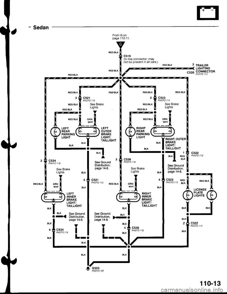
- Sedan
Frorn G onpage 110-11.
c516(ln line connector: maynot be present in all cars.)
FEO/BLK
3
FED/BLK
FED/ALK
c521
See BrakeLights
REO/BLK
FEO/BLK
NED/BIK
See Brake
3 tnatLenLIGHTINGnqrn CONNECTOR
cs22
c522
FLuiRIGHTREARPARKINGLIGHT
BLK
*-li,fr,t;;'-
FI
Sge GroundDistribution,
1BED/BLKc536
c521
ritr
INNERBRAKELIGHT/TAILLIGHT
RIGHTINNERBRAKELIGHT/TAILLIGHT
LICENSEPLATELIGHTS
*-r
a
ALK
BIK See Groundr< Distribution,S€s GroundDistributign,page 14-8.
V
I
".":^l>-o
"'fI
".*f
"^IJ
page 14-8.
Y
,"rt:A r* I
BLK
c536
L-
110-13
Page 1602 of 1681
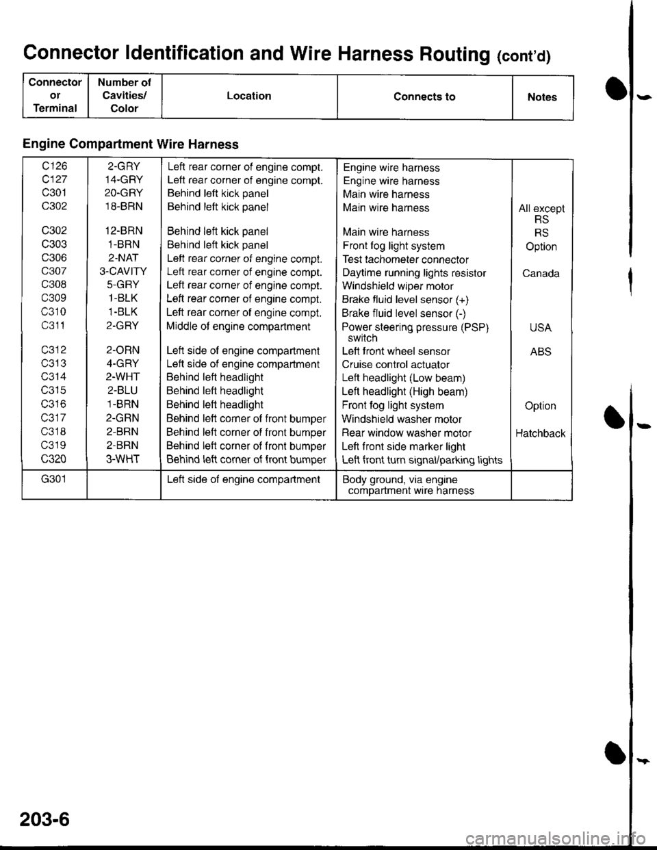
Connector ldentification and Wire Harness Routing (cont'd)
Connector
or
Terminal
Number of
Cavities/
Color
LocationConnects toNotes
Engine Compartment Wire Harness
wt10
c127
c301
c302
c302
c303
c306
c307
c308
c309
c310
c311
T/JIJ
c314
c315
IJJ IO
c317
c318
c319
c320
2.GRY
14-GBY
2O-GRY
18-BRN
12-BRN
1-BRN
2.NAT
3.CAVITY
J-(l|-I Y
1-BLK
1-BLK
Z-IfFI T
2-ORN
4-GRY
2-WHT
2-BLU
1-BRN
2-GRN
2-BRN
2-BRN
3-WHT
Left rear corner of engine compt.
Left rear corner of engine compt.
Behind left kick panel
Behind left kick panel
Behind left kick panel
Behind left kick panel
Left rear corner of engine compt.
Left rear corner of engine compt.
Left rear corner of engine compt.
Left rear corner of engine compt.
Left rear corner of engine compt.
Middle of engine compartment
Left side of engine compartment
Lett side of engine compartment
Behind left headlight
Behind left headlight
Behind left headlight
Behind left corner of front bumper
Behind left corner of front bumper
Behind left corner of fronl bumper
Behind left corner of {ront bumper
Engine wire harness
Engine wire harness
Main wire harness
Main wire harness
Main wire harness
Front log light system
Test tachometer connector
Daytime running lights resistor
Windshield wlper motor
Brake fluid level sensor (+)
Brake fluid level sensor (-)
Power steering pressure (PSP)
switch
Left front wheel sensor
Cruise control actuator
Left headlight (Low beam)
Left headlight (High beam)
Front fog light system
Windshield washer motor
Rear window washer molor
Left front side marker light
Left front turn signal/parking lights
All except
RS
RS
Option
Canada
USA
ABS
Option
Hatchback
G301Left side of engine compartmentBody ground, via engine
comDartment wire harness
203-6
Page 1610 of 1681
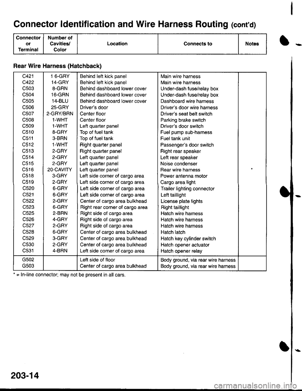
Connector ldentification and Wire Harness Routing (cont'd)
Connector
ol
Terminal
Number of
Cavities/
Color
LocationConnects toNotes
Rear Wire Harness (Hatchback)
c421
c422
cs03
c504
c505
UCUO
c507
c508
c509
c510
c511
c512
cs13
c514
c515
ucto
c518
c519
c520
c521
c522
c523
uczc
c526
c527
c528
c529
c530
c531
1 6-GRY
14-GRY
8-GRN
16-GRN
14-BLU
25.GRY
2.GRY/BRN
1-WHT
1-WHT
8-GRY
3-BRN
1-WHT
2-GRY
2-GRY
2-GRY
20-cAVtry
3-GRY
2.GRY
6-GRY
6-GRY
2-GRY
6-GRY
2-BRN
4.GRY
2.GRY
6-GRY
3-GRY
2-GRY
4-BRN
Behind left kick panel
Behind left kick panel
Behind dashboard lower cover
Behind dashboard lower cover
Behind dashboard lower cover
Driver's door
Center floor
Center floor
Left quarter panel
Top of tuel tank
Top of fuel tank
Right quarter panel
Right quarter panel
Left quarter panel
Left quarter panel
Lett quaner panel
Left side corner of cargo area
Left side corner of cargo area
Left side corner of cargo area
Left side corner of cargo area
Center of cargo area bulkhead
Right rear corner of cargo area
Right side of cargo area
Right side of cargo area
Right side of cargo area
Center of cargo area bulkhead
Center of cargo area bulkhead
Center of cargo area bulkhead
Left side corner of cargo area
Main wire harness
Main wire harness
Under-dash fuse/relay box
Under-dash fuse/relay box
Dashboard wire harness
Driver's door wire harness
Driver's seat belt switch
Parking brake switch
Driver's door switch
Fuel pump sub-harness
Fuel tank unit
Passenger's door switch
Right rear speaker
Left rear speaker
Noise condenser
Rear wire harness
Power antenna motor
Cargo area light
Trailer lighting connector
Lett taillight
License plate lights
Right taillight
Hatch wire harness
Hatch wire harness
Hatch wire harness
Hatch latch
Hatch key cylinder switch
Hatch opener actuator
Hatch opener relay
G502
\,CUJ
Lett side of floor
Center ot cargo area bulkhead
Body ground, via rear wire hamess
Body ground, via rear wire hamess
. = Inline connector: mav not be oresent in all cars.
203-14
Page 1612 of 1681
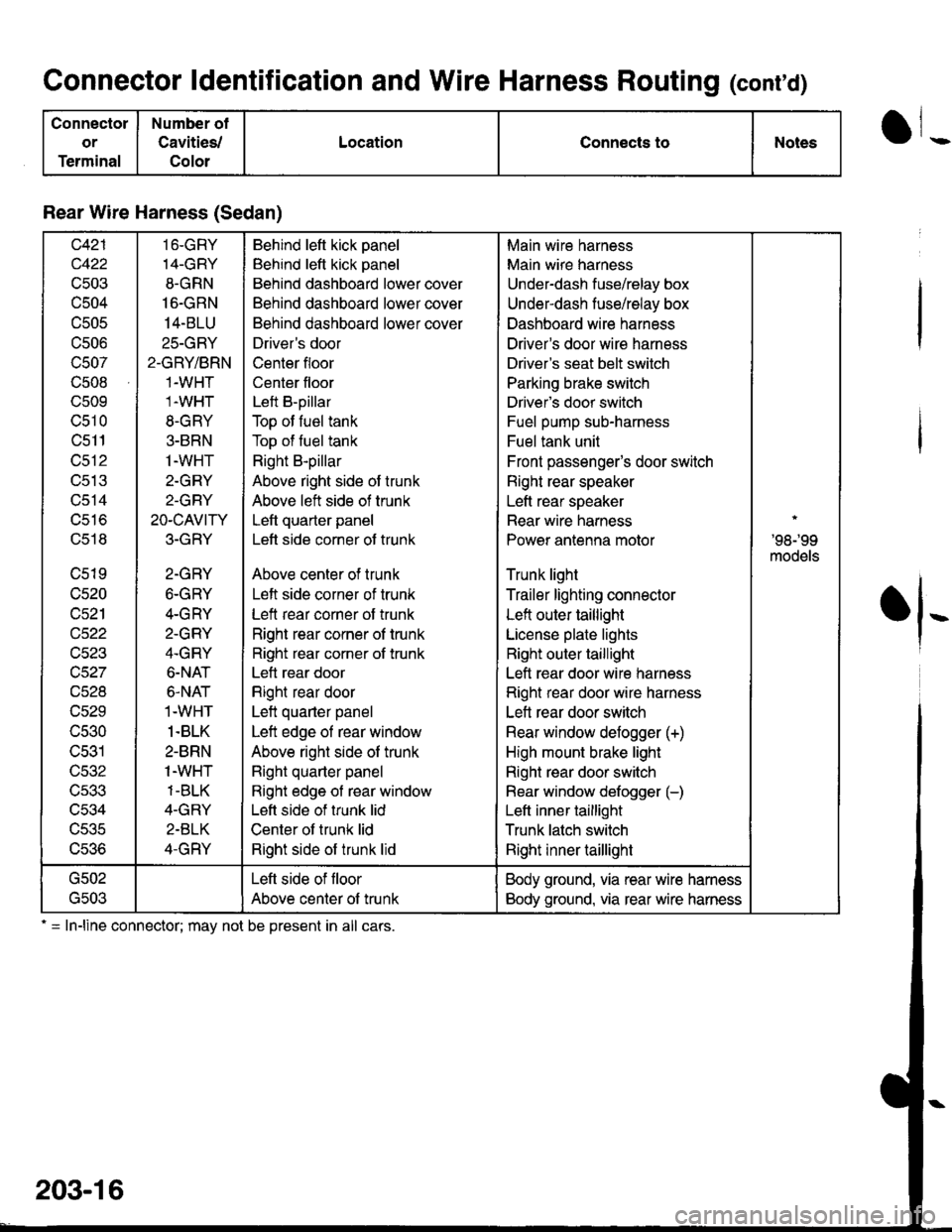
Connector ldentification and Wire Harness Routing (conrd)
Connectol
or
Terminal
Number ot
Cavities/
Colol
LocationConnects toNotes
Rear Wire Harness (Sedan)
c421
c422
c503
c504
c505
c506
c507
c508
c509
c510
c511
c512
UCIJ
c514
uSto
c518
c519
c520
c521
v)11
c523
c527
vczd
c529
c530
c531
c532
c533
c534
UCJC
L,c.to
16-GRY
14-GRY
8-GRN
16-GRN
14-BLU
25-GRY
2-GRY/BRN
1-WHT
1.WHT
8-GRY
3-BRN
1-WHT
2-GRY
2-GRY
2O-CAVITY
3-GRY
2-GRY
6-GRY
4-GRY
2-GRY
4-GRY
6-NAT
6.NAT
1.WHT
1.BLK
2-BRN
1-WHT
1-BLK
4-GRY
2.BLK
4-GRY
Behind left kick panel
Behind left kick panel
Behind dashboard lower cover
Behind dashboard lower cover
Behind dashboard lower cover
Driver's door
Center floor
Center floor
Left B-pillar
Top of fuel tank
Top of fuel tank
Right B-pillar
Above right side of trunk
Above left side of trunk
Left quarter panel
Lett side corner of trunk
Above center of trunk
Left side corner of trunk
Left rear corner of trunk
Right rear corner of trunk
Right rear corner of trunk
Lett rear door
Right rear door
Left quarter panel
Left edge ol rear window
Above right side of trunk
Right quarter panel
Right edge of rear window
Left side of trunk lid
Center ot trunk lid
Right side of trunk lid
Main wire harness
Main wire harness
Under-dash fuse/relay box
Under-dash fuse/relay box
Dashboard wire harness
Driver's door wire harness
Driver's seat belt switch
Parking brake switch
Driver's door switch
Fuel pump sub-harness
Fuel tank unit
Front passenger's door switch
Right rear speaker
Left rear speaker
Rear wire harness
Power antenna motor
Trunk light
Trailer lighting connector
Left outer taillight
License plate lights
Right outer taillight
Left rear door wire harness
Right rear door wire harness
Lett rear door switch
Rear window defogger (+)
High mount brake light
Right rear door switch
Rear window defogger (-)
Left inner taillight
Trunk latch switch
Right inner taillight
'98r99
models
G502
G503
Left side of floor
Above center of trunk
Body ground, via rear wire harness
Body ground, via rear wire harness
.l-
= In-line connector; may not be present in all cars.
203-16