Page 1085 of 1681
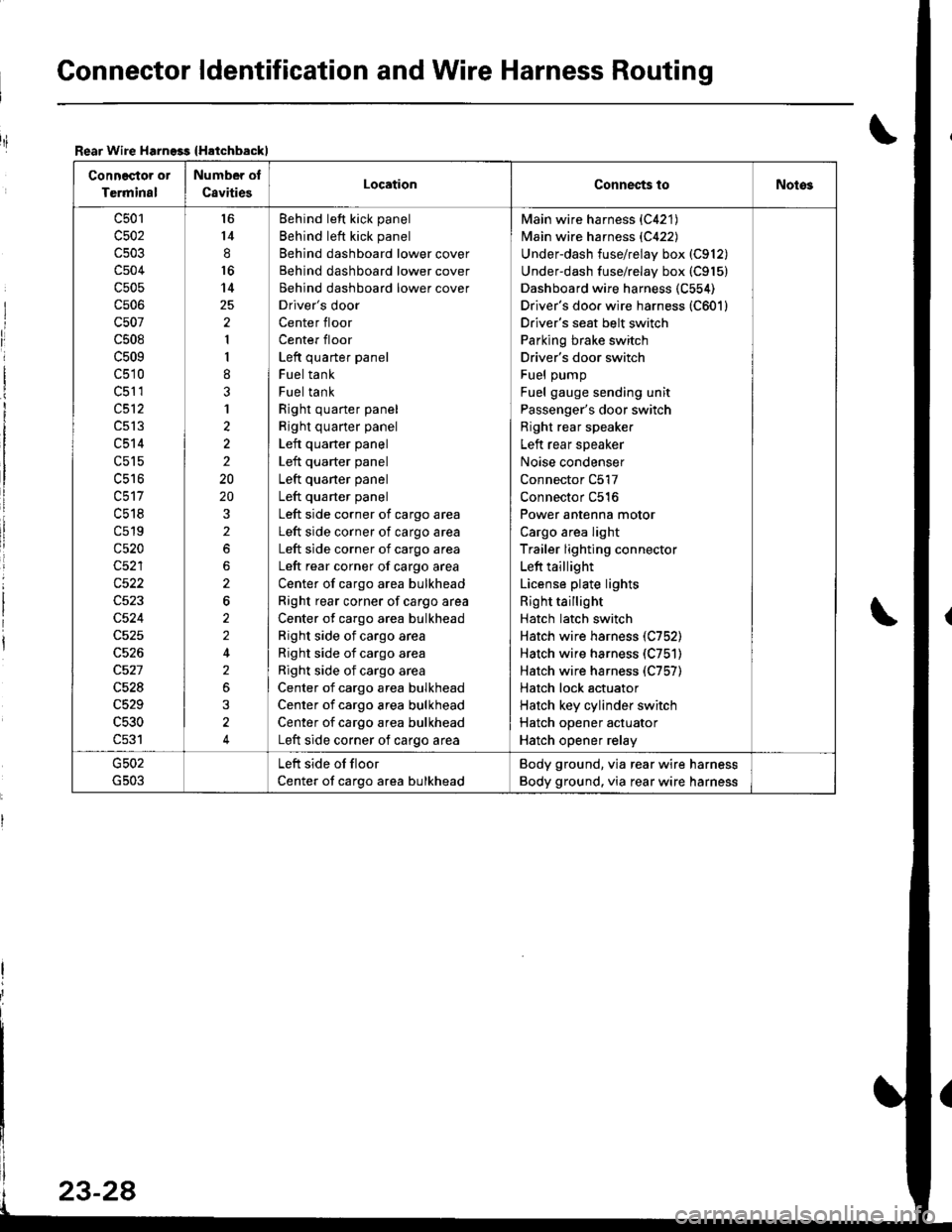
Gonnector ldentification and Wire Harness Routing
Rear Wire Harngss {Hatchbackl
Connector or
Terminal
Number of
C8vitiesLocationConnec{s toNotos
c501
c502
c504
c505
cs06
c507
c508
c509
c510
c51 1
c512
c513
c514
c515
uc to
c518
c519
c520
c522
c524
c528
c529
c530
c531
l6
14
8
16
14
2
1
I
8
3
1
2
2
2
20
20
2
2
6
2
2
2
3
4
Behind left kick panel
Behind left kick panel
Behind dashboard lower cover
Behind dashboard lower cover
Behind dashboard lower cover
Driver's door
Center floor
Center floor
Left quarter panel
Fuel tank
Fuel tank
Right quarter panel
Right quarter panel
Left quarter panel
Left quarter panel
Left quaner panel
Left quarter panel
Left side corner of cargo area
Left side corner of cargo area
Left side corner of cargo area
Left rear corner of cargo area
Center of cargo area bulkhead
Right rear corner of cargo area
Center of cargo area bulkhead
Right side of cargo area
Right side of cargo area
Right side of cargo area
Center of cargo area bulkhead
Center of cargo area bulkhead
Center of cargo area bulkhead
Left side corner of cargo area
Main wire harness {C421)
Main wire harness {C422)
Underdash fuse/relay box (C912)
Underdash fuse/relay box (C915)
Dashboard wire harness (C554)
Driver's doo. wire harness (C601)
Driver's seat belt switch
Parking brake switch
Driver's door switch
Fuel pump
Fuel gauge sending unit
Passenger's door switch
Right rear speaker
Left rear speaker
Noise condenser
Connector C517
Connector C516
Power antenna motor
Cargo area light
Trailer lighting connector
Left taillight
License plate lights
Right taillight
Hatch latch switch
Hatch wire harness (C752)
Hatch wire harness (C751)
Hatch wire harness (C757)
Hatch lock actuator
Hatch key cylinder switch
Hatch opener actuator
Hatch opener relay
Left side of floor
Center of cargo area bulkhead
Body ground, via rear wire harness
Body ground. via rear wire harness
riI
Page 1087 of 1681
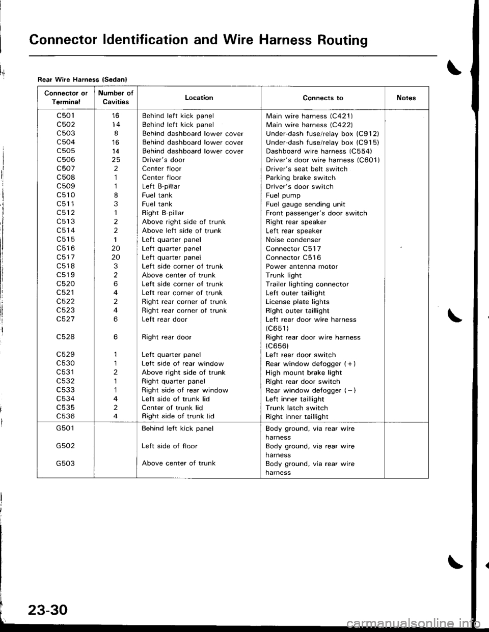
Connector ldentification and Wire Harness Routing
Connector or
Terminal
Numbel of
CavitiesLocationConnects toNotes
c501
c502
c503
c504
c505
c506
c507
c508
c509
c5l0
c511
c512
c513
c514
c515
c517
c518
c519
c520
c521
c522
c523
c527
c528
c529
c530
c531
c532
c533
c534
c535
cs36
14
8
14
2
1
1
8
3
1
2
2
1
20
20
3
2
6
4
2
4
6
6
1
1
2
1
1
4
2
4
Behind left kick panel
Behind left kick panel
Behind dashboard lower cover
Behind dashboard lower cover
Behind dashboard lower cover
Driver's door
Center floor
Center floor
Left B-pillar
Fuel tank
Fuel tank
Right B pillar
Above right side of trunk
Above left side of trunk
Left quarter panel| .{+ ^',rrrar ^rnal
Left quarter panel
Left side corner of trunk
Above center of trunk
Left side corner of trunk
Left rear corner of trunk
Right rear corner o{ trunk
Right rear corner ot trunk
Lelt rear door
Right rear door
Left quarter panel
Left side of rear window
Above right side of trunk
Right quarter panel
Right side of rear window
Left side of trunk lid
Center of trunk lid
Right side of trunk lid
lvlain wire harness (C421 )
lvlain wire harness (C422)
Underdash fuse/relay box (C912)
Under dash fuse/relay box (C915)
Dashboard wire harness (C554)
Driver's door wire harness (C6Ol)
Driver's seat belt switch
Parking brake switch
Driver's door switch
Fuel pump
Fuel gauge sending unit
Front passenger's door switch
Right rear speaker
Left rear speaker
Noise condenser
Connector C517
Connector C516
Power antenna motor
Trunk light
Trailer lighting connector
Left outer taillight
License plate lights
Right outer taillight
Lett rear door wire harness
(c651)
Right rear door wire harness
1C656)
Left rear door switch
Rear window defogger {+ )
High mount brake light
Right rear door switch
Rear window detogger (- I
Left inner taillight
Trunk latch switch
Right inner taillight
G501
G502
G503
Behind left kick panel
Left side of tloor
Above center of trunk
Body ground, via rear wire
harness
Body ground, via rear wire
harness
Body ground, via rear wire
harness
Rear Wire Hamess {Sedan}
I
ri
I
i
I
li
!
Page 1120 of 1681
J
BrK-
BrK---
Lell headlighl {High beam)
Lell headlighl (Low beam)Cruise conlro aclualor
Lell lrcfl parkirElurn signallighlLell lront slde maker lighl
Windshield wiper molor
Wndshleld )I Wasner molor
Brake lluid level switchPower sleenng pressure (PSP)swilch (USA)
BLK - Healer lanswlch
J
EL^- Enrlron {€y swrcn- Data [nk conneclor |DLC)
BL(
Fronl passenge/s door key cylinder switdrFronl passonger's door lock swilch
Seavice cieck conneclorClulch swilch (MIT wilh crLr se conlrol)Inle ock contfolunit l ,^-,Parking prn swlch J u' t
Windshi€ld wipefl^Iasher sw 1ch
G40l
tr
tr
N
: Eng ne companmentwife harness
: Fronl passenge/s door wire hamess
: Healer sub.harness A
: Healer sutsharness B
tr
4)(cont'd)
G3o1
(From page 23-62)
;L^ ------ A/T gear posrron sw cn
l- Cldch inledock sw cl rM/.'- Fear window w pe,,wdsl'er sw cl
_l__{BLK_-
UNDER.OASH FUSE/RELAY BOX(To page 23 64)
Page 1177 of 1681
Gauge Assembly
Component Location Index
VEHICLE SPEED SENSOR {VSSITest, page 23-128Input Test, page 23-128Replacement, page 23-130
GAUGE ASSEMBLYGauge Location Index, page 23-12:|fndicator Location Index. page 23-121Terminal Location Index, page 23-121Eulb Location, pag6 23-122Disassembly, page 23-127Removal, paqe 23-126
FUEL GAUGE SENDING UNITTest, page 23-132Replacement, page 23-132
PARKING BRAKE SWNCHTest, page 23-135
ARAKE FLUID LEVEL SWITCHTest, page 23,135
ENGINE OIL PRESSURE SWITCHTest, p6ge 23-130
ENGINE COOLANT TEMPERATUFE IECTI GAUGESENOING UNITTest, page 23-134
23-120
Page 1192 of 1681
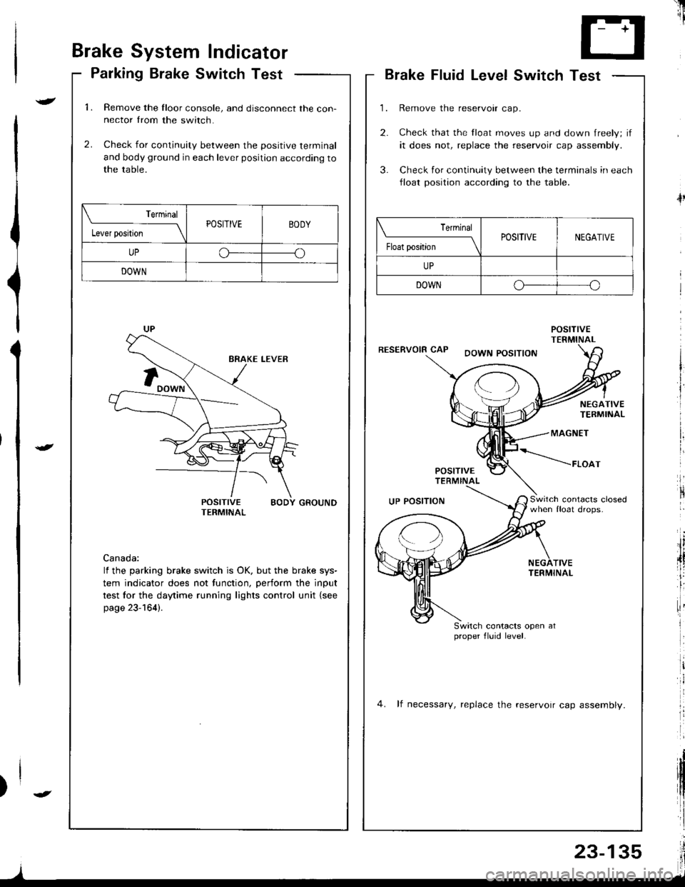
Brake System Indicator
Parking Brake Switch Test
1.Remove the Iloor console, and disconnect the con-nector from the switch.
Check for continuity between the positive terminal
and body ground in each lever position according tothe table.
2.
POSITIVE BODY GROUNDTERMINAL
Canada:
lf the parking brake switch is OK, but the brake sys-
tem indicator does not function, perform the input
test for the daytime running lights control unit {see
page 23-164).
Terminal
l"*rr*ril---ltPOSITIVEBODY
UPoo
DOWN
'il
--r '1i
T- +T
L.J
Brake Fluid LevelSwitch Test
Remove the reservoir cap.
Check that the float moves up and down freely; if
it does not, replace the reservoir cap assembly.
Check for continuity between the terminals in each
lloat position according to the table.
POStnVETERMINALRESERVOIR CAPDOWN POSITION
4l
NEGATIVETERMINAL
MAGNET
POSITTVETERMINAL
*----raoo,
Switch contacrs closedwhen float drops.UP POSITION
TIVETERMINAL
Switch contacts open atproper fluid level.
4. lf necessary, replace the reservoir cap assemblv.
| ermrnal
Float position \POSITIVENEGATIVE
UP
DOWNo--o
I
Page 1203 of 1681
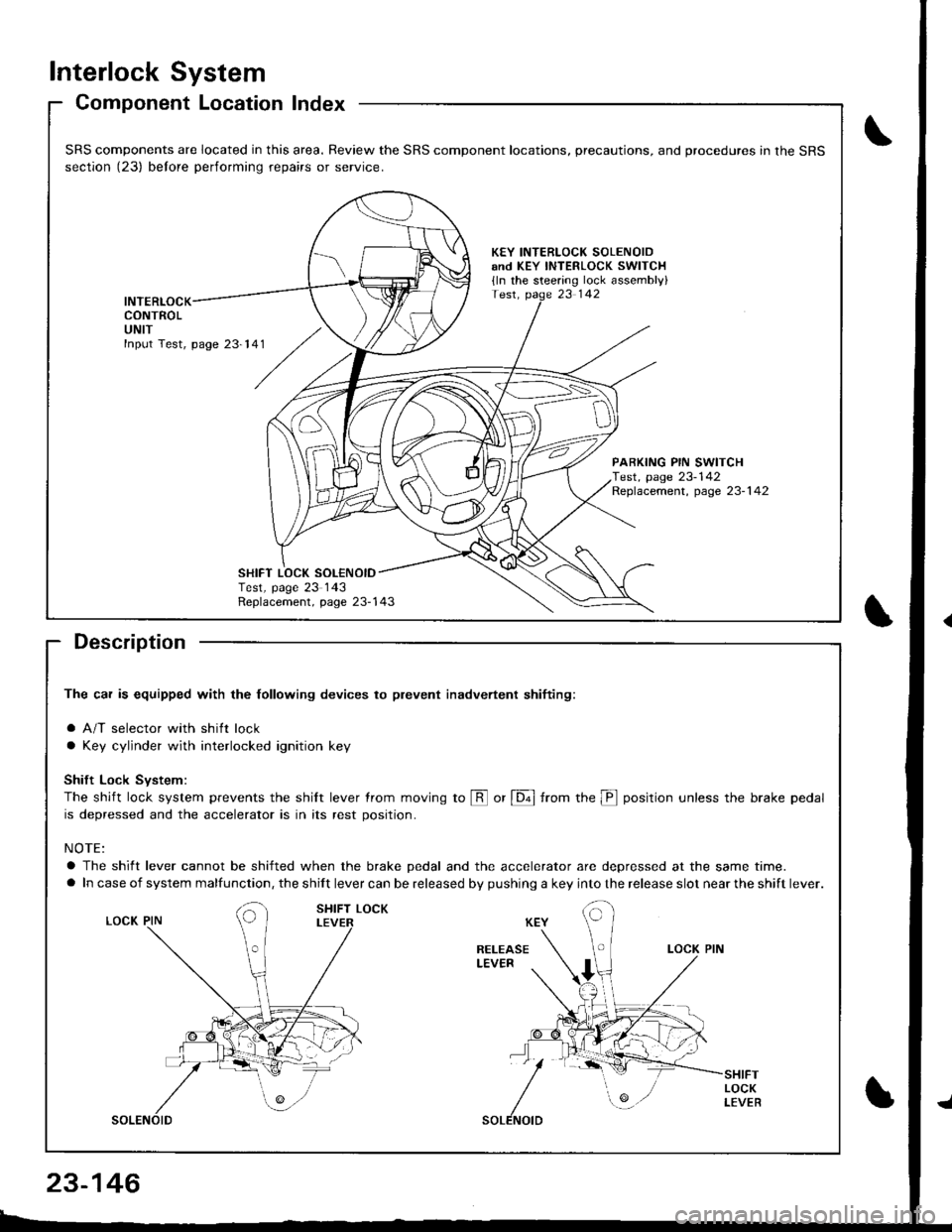
Interlock System
Component Location Index
Description
The car is equipped with the lollowing devices to plevent inadvertent shifiing:
a A/T selector with shift lock
a Key cylinder with interlocked ignition key
Shift Lock Svstem:
The shift lock system prevents the shilt lever trom moving to @ or [6ol from the p position unless the brake pedal
is depressed and the accelerator is in its rest position.
NOTE:
a The shift lever cannot be shifted when the brake pedal and the accelerator are depressed at the same time.
a In case of system malfunction, the shift lever can be released by pushing a key into the release slot near the shift lever.
SRS components are located in this area. Review the SRS component locations, precautions, and procedures in the SRS
section (23) belore performing repairs or service.
KEY INTERLOCK SOLENOIDand KEY INTERLOCK swlTCH
{ln the steering lock assembly}
INTERLOCKCONTROLUNIT
PARKING PIN SWITCHTest, page 23-142Replacement, page 23-1 42
Replacement, page 23-143
SHIFT LOCK SOL€NOIDTest, page 23 143
23-146
Page 1206 of 1681
){r/
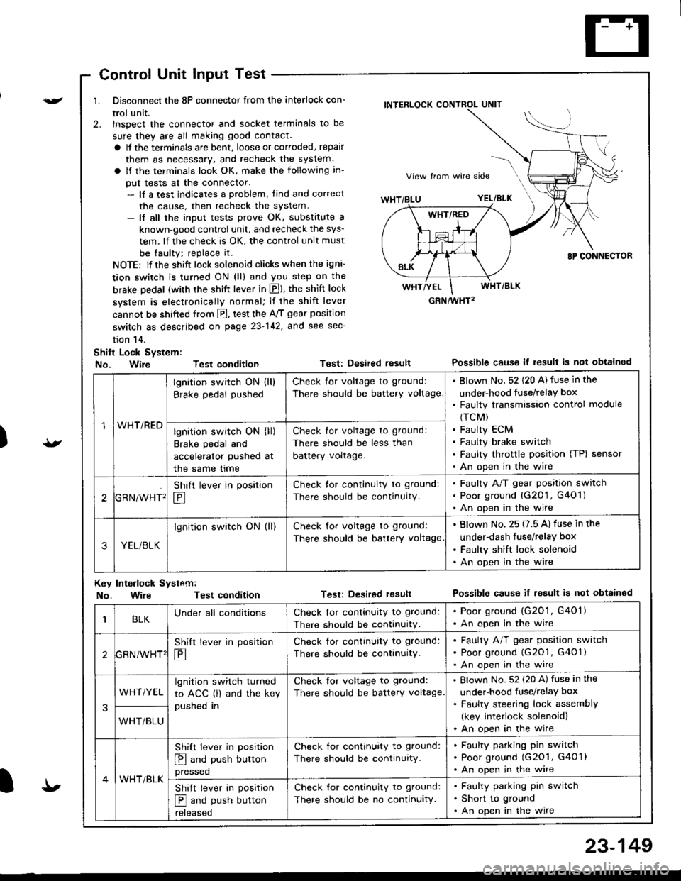
Control Unit Input Test
1. Disconnect the 8P connector from the interlock con-
trol unit.
2. lnspect the connector and socket terminals to be
sure they are all making good contact.
a It the terminals are bent, loose or corroded, repair
them as necessary, and recheck the system.
a lf the terminals look OK, make the following in-
put tests at the connector.- lf a test indicates a problem, tind and correct
the cause, then recheck the system.- lf all the input tests prove OK, substitute a
known-good control unit, and recheck the sys-
tem. lf the check is OK, the control unit must
be faulty; replace it.
NOTE: lf the shift lock solenoid clicks when the igni-
tion switch is turned ON (ll) and you step on the
brske Dedal (with the shift lever in E). the shift lock
system is electronically normal; if the shift lever
cannot be shifted from fl, test the 46 gear position
switch as described on page 23-142, and see sec-
tion 14.
Shift Lock System:
No. Wire Test condition
No. WireTest condition
Test: Desired resultPossible causs it result is not obtained
Test: Dcsired lesultPossible cause it result is not obtainsd
INTERLOCK CONTROL UNIT
GRN/wHT2
1WHT/RED
lgnition switch ON (ll)
Brake pedal pushed
Check for voltage to ground:
There should be battery voltage
Blown No. 52 {20 A) fuse in the
under-hood fuse/relaY box
Faulty transmission control module
(TCM)
Faulty ECM
Faulty brake switch
Faulty throttle position (TP) sensor
An open in the wire
lgnition switch ON (ll)
Brake pedal and
accelerator pushed at
the same me
Check for voltage to ground:
There should be less than
battery voltage.
tGRN/WHT'
Shift lever in position
E
Check tor continuity to ground:
There should be continuity.
Faulty A/T gear position switch
Poor ground {G20'1 , G401)
An open in the wire
3YEL/BLK
lgnition switch ON (ll)Check for voltage to ground:
There should be battery voltage
Blown No. 25 (7.5 A) fuse in the
under-dash fuse/relay box
Faulty shift lock solenoid
An open in the wire
Key Int€rlock Systcm:
BLKUnder all conditionsCheck lor continuity to ground:
There should be continuitY.
. Poor ground (G201, G401). An open in the wire
GRNiWHT'
Shift lever in position
E
Check for continuity to ground:
There should be continuity.
Faulty A/T gear position switch
Poor ground {G2O1, G401 }
An open in the wire
3
WHT/YELlgnition switch turned
to ACC (l) and the key
pushed in
Check tor voltage to ground:
There should be battery voltage.
Blown No. 52 (20 A) fuse in the
under-hood fuse/relaY box
Faulty steering lock assemblY
(key interlock solenoidl
An open in the wireWHT/BLU
4WHT/BLK
Shift lever in position
E and push button
pressed
Check for continuity to ground:
There should be continuity.
Faulty pafking pin switch
Poor ground (G2O1, G4O 1)
An open in the wire
Shift lever in position
E and push button
reteaseo
Check for continuity to ground:
There should be no continuity.
Faulty parking pin switch
Short to ground
An open in the wire
I'
23-149
Page 1214 of 1681
M
lgnition switch at
START iIII)
Check for voltage to ground:
There should be battery voltage.
Blown No.31 (7.5 A) fuse in the
under-dash fuse/relay box
Faulty clutch interlock switch or
starter cut relay (M/T)
Faulty neutral position switch (A/T)
An open in the wire
2D
lgnition switch ON {ll).
brake fluid reservoir
full, and parking brake
tever oown
Connect to ground: Brake
system light should come on.
. Blown brake system light. An open in the wire
Bulb Check System (brake system light)
No. Terminal Test conditionTost: Desiled resultPossiblo cause if lesult is not obtained
)
)
23-157