Page 630 of 1681
4.Tap on the transmission housing side of the ditferen-tial assembly with the special tool to seat thedifferential assembly in the torque convener housing.
o.
Measure the clearanc; between the thrust shim and
outer race of the ball bearing in the transmission
nousrng.
STANDARD: O-0.15 mm (O-O.O06 in)
It out of limits. select a new thrust shim from the
tollowing table:
THRUST SHIM, 80 mm
NOTE: Il the thrust shim-to-ball bearing outer race
clearance measured in step 5 is within the standard,
it is not necessary to perform steps 7 and 8.
Remove the transmission housing.
Replace the 2.50 mm {0.098 in) thrust shim with
the one of the correct thickness selected in step 6.
Install the transmission housing (see sectjon 14).
7.
L
Part NumberThickness
904r4-689-000
90415-689-000
90416-689*000
90417-689-OOO
90418-689-O00
90419-PH8-000
2.50 mm (0.09843 in
2.60 mm (0.10236 in
2.70 mm (O.10630 in
2.80 mm {O. 1 1O24 in
2.90 mm {O.1 141 6 in
3.OO mm (O. l '181 1 in
9.
Page 646 of 1681

Intermediate Shaft
Removal
Drain the transmission oil or fluid {see section 13 or
14t.
Remove the left driveshaft (see page 16-3).
Bemove the three dowel bolts.
Remove the intermediate sh8ft from the differential.
CAUTION: Hold the intermediate shaft horizontal
until it is clear ot th6 difforantirl to prevont damage
to thc ditf€rential oil seal.
7. Install the knuckle on the lower arm.
NOTE: Wipe off the grease before tightening the
nut at the ball joint.
CAUTION:
. Be careful not to damago the ballioint boot.
. Torque the castle nut to tho low€r torque speci-
tication, then tighten it only lar onough to align
th6 slot whh tho pin hols. Do not align the nut
by loosening.
,.<__coTTEF PtNCASTLE NUT12 x 1.25 mm49 - 59 N.m {5.0 - 5.0 kgf.m, 36 - t3 lbl.ft)
Beplace.On reassembly,bend the cotter pin
8. Install a new spindle nut, then tighten the nut.
9. Installthe front wheel with the wheel nuts.
NOTE: Before installing the wheel, clean the mating
surfaces of the brake disc and the wheel.
FRONT WHEELWH€EL NUT 12 x 1.5 mm108 N.m (11.0 kgt m,80lbf ft)
10.
NUT 22 x '1.5 mm181 N m 118.5 kgl.m, 134lbtftlNOTE: After tightening, use a drift tostake the spindle nut shoulderagainst the driveshatt.
Tighten the flange bolts and the new self-locking
nut with the vehicle's weight on the damper.
Refill the transmission with recommended oil or
fluid (see section 13 or 14).
11.
12. Check the front wheel alignment and adjust if nec-
essary (see page 18-4).
INTERMCOIATE SHAFT
16-15
Page 1135 of 1681

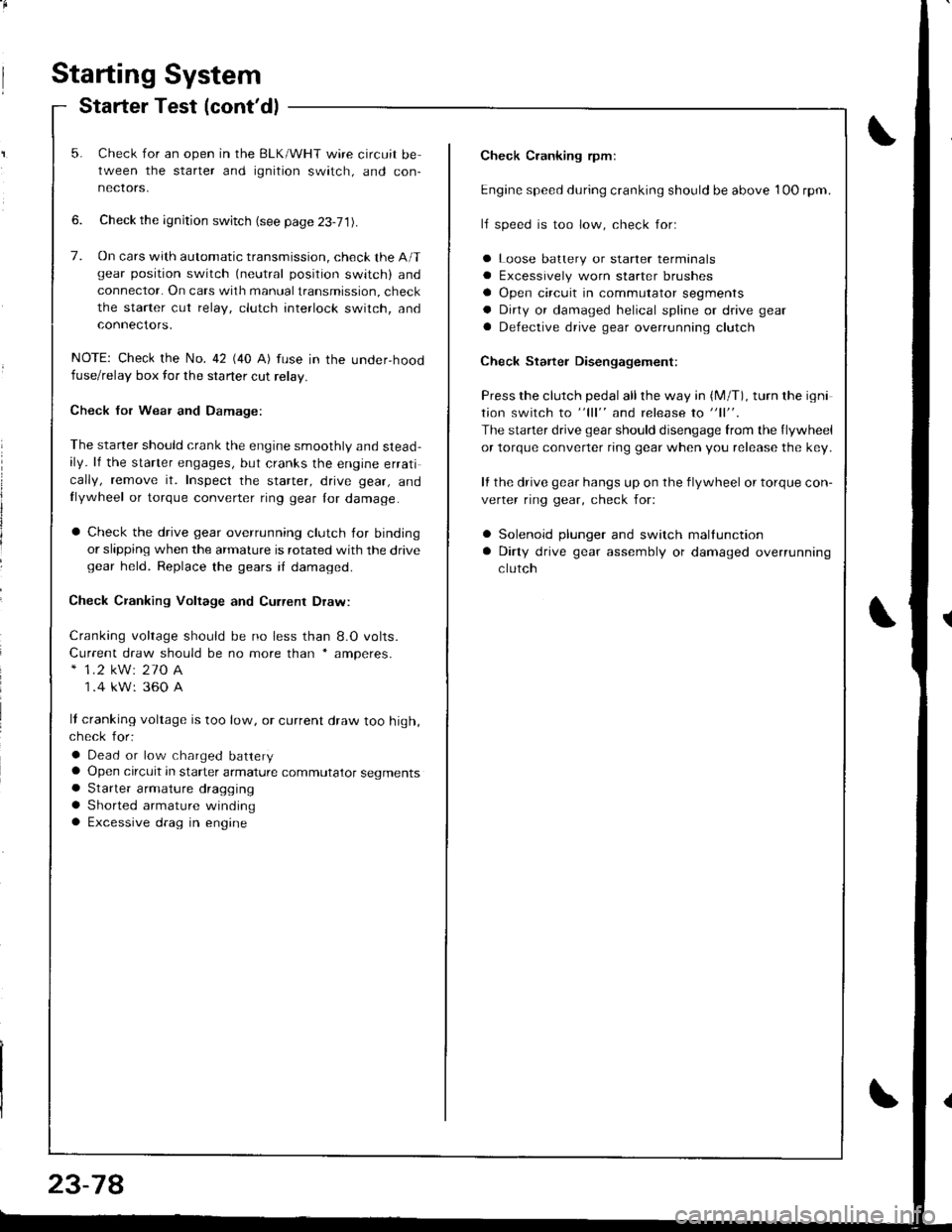
Starting System
Starter Test (cont'dl
Check Cranking rpmr
Engine speed during cranking should be above 1OO rpm.
lJ speed is too low, check for:
a Loose batlery or starter terminals
a Excessively worn starter brushes
a Open circuit in commutator segments
a Dirty or damaged helical spline or drive gear
a Defective drive gear overrunning clutch
Check Starter Disengagement:
Press the clutch pedal all the way in (M/T), turn rhe igni
tion switch to "lll" and release to "11".
The starter drive gear should disengage from the flywheel
or torque converter ring gear when you release the key.
It the drive gear hangs up on the flywheel or torque con-
verter ring gear, check for:
a Solenoid plunger and switch mallunction
a Dirty drive gear assembly or damaged overrunning
clutch
5. Check for an open in the BLK/WHT wire circuit be
tween the starter and ignition switch, and con-
necrors,
6. Check the ignition switch (see page 23-71).
7. On cars with automatic transmission, check the A/Tgear position switch (neutral position switch) and
connector. On cars with manualtransmission, check
the starter cut relay, clutch interlock switch, and
connectors.
NOTE: Check the No. 42 (40 A) fuse in the under,hoodfuse/relay box for the starter cut relay.
Check Jor Wear and Damage:
The starter should crank the engine smoothly and stead,ily. lf the starter engages, but cranks the engine errati
cally, remove it. Inspect the starter, drive gear, andllywheel or torque converter ring gear lor damage.
a Check the drive gear overrunning clutch for binding
or slipping when the armature is rotated with the drivegear held. Replace the gears i{ damaged.
Check CJanking Voltage and Current Draw:
Cranking voltage should be no less than 8.O volts.
Current draw should be no more than * amperes.* 1.2 kW: 27O A
1 .4 kW: 360 A
It cranking voltage is too low, or current draw too high,check for:
a Dead or low charged batterya Open circuit in starter armature commutator segmentsa Starter armalure dragging
a Shorted armature windinga Excessive drag in engine
Page 1186 of 1681
Test tho vss:1. Turn the ignition switch OFF.2. Connect the other test harness connector to the VSS.3. Raise th€ front and roar of thevehicle, and support it withsafety stands.4. Put the transmission in neu-tral with the ignition switchoN flr).5. Slowly rotate one wheel withthe other wheel blocked.
Does voltage pulse from 0 toapprox.5 V or more?
Spocdomatcr Te3t:1. Disconnoct the 16P conngctor"B" from the gauge assem-
2. Touch 8 probe to the ORNwire, and connect it to bodyground through a voltmetor.3. Slowly rotate one wheel withthe other wheel blocked.
Repair open in the ORN and BLU/WHT wire botw.en tho VSS .ndthe soa€do-mster.
Does the meter indicate puls-ing voltage?
{
{
WHT TESTCLIP
TEST HABNESSOTLAJ - PT3O2OA
FED TEST HARNESSCLIPGRN TEST HARNESS CLIP
GAUGE ASSEMBLY 16P CONNECTOR '8"
PROTECTIVETAPE
){
Page 1193 of 1681
MAINTENANCE BEMINDER LIGHT{ln the gauge assembly)Gauge Assembly. page 23-120
VEHICLE SPEED SENSOR IVSS)(On th6 transmission housing)Test, page 23-128, 129Replacement, page 23-130
MAIMTENANCE REMINDER UNIT(Behind th€ dashboard lower cover)Input T6st, page 23-139
Maintenance Reminder System
Component Location Index
\
t
23-136
I
Page 1198 of 1681
Circuit Diagram
)
{
{
I
UNDER-HOOD FUSEiRELAY 80XIGN TIONSWITCHUNDER-DASHFUSE/RELAY BOX
. TRANSMISS]ONCONTROLMODULE (TCM)
/;; l-^--;;;;lw--BLh ---wrl f ,:+ BLK/E- t.d\o-ft\---l
I t,;:'*'
IVECM
f7
ILT GRN/BLK
YEUBLU
(n lhe gauqe assembly)D4
TRANSMISSIONCONTROLMODULErrcM)
f7
IIGRN/BLK
c6c7c8 lc9NTERLOCKCONTROLUNIT (
f7
IGRNMHT
BLK
TRANSMISSION CONTROLMODULE TICM)GRNCRN]BLULTGRNMHT
GRN/YEL
No l9 (104)FUSE
f7
IRED/BLK
A?TGEARPOSITION SWTCHRED
II
I
Y?
DASH LIGHTSBFIGHTNESSCONTROLLER
BLK
oro,G40lG20lG401
A/T GEAH POSITION NDICATOR DIMMING C RCUIT
A/T GEARPOS TIONCONSOLELIGHT(1.4w)
/ ,/ t2
{,
23-141
Page 1206 of 1681

){r/
Control Unit Input Test
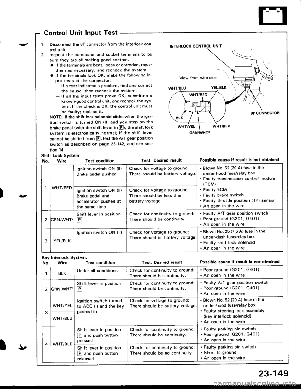
1. Disconnect the 8P connector from the interlock con-
trol unit.
2. lnspect the connector and socket terminals to be
sure they are all making good contact.
a It the terminals are bent, loose or corroded, repair
them as necessary, and recheck the system.
a lf the terminals look OK, make the following in-
put tests at the connector.- lf a test indicates a problem, tind and correct
the cause, then recheck the system.- lf all the input tests prove OK, substitute a
known-good control unit, and recheck the sys-
tem. lf the check is OK, the control unit must
be faulty; replace it.
NOTE: lf the shift lock solenoid clicks when the igni-
tion switch is turned ON (ll) and you step on the
brske Dedal (with the shift lever in E). the shift lock
system is electronically normal; if the shift lever
cannot be shifted from fl, test the 46 gear position
switch as described on page 23-142, and see sec-
tion 14.
Shift Lock System:
No. Wire Test condition
No. WireTest condition
Test: Desired resultPossible causs it result is not obtained
Test: Dcsired lesultPossible cause it result is not obtainsd
INTERLOCK CONTROL UNIT
GRN/wHT2
1WHT/RED
lgnition switch ON (ll)
Brake pedal pushed
Check for voltage to ground:
There should be battery voltage
Blown No. 52 {20 A) fuse in the
under-hood fuse/relaY box
Faulty transmission control module
(TCM)
Faulty ECM
Faulty brake switch
Faulty throttle position (TP) sensor
An open in the wire
lgnition switch ON (ll)
Brake pedal and
accelerator pushed at
the same me
Check for voltage to ground:
There should be less than
battery voltage.
tGRN/WHT'
Shift lever in position
E
Check tor continuity to ground:
There should be continuity.
Faulty A/T gear position switch
Poor ground {G20'1 , G401)
An open in the wire
3YEL/BLK
lgnition switch ON (ll)Check for voltage to ground:
There should be battery voltage
Blown No. 25 (7.5 A) fuse in the
under-dash fuse/relay box
Faulty shift lock solenoid
An open in the wire
Key Int€rlock Systcm:
BLKUnder all conditionsCheck lor continuity to ground:
There should be continuitY.
. Poor ground (G201, G401). An open in the wire
GRNiWHT'
Shift lever in position
E
Check for continuity to ground:
There should be continuity.
Faulty A/T gear position switch
Poor ground {G2O1, G401 }
An open in the wire
3
WHT/YELlgnition switch turned
to ACC (l) and the key
pushed in
Check tor voltage to ground:
There should be battery voltage.
Blown No. 52 (20 A) fuse in the
under-hood fuse/relaY box
Faulty steering lock assemblY
(key interlock solenoidl
An open in the wireWHT/BLU
4WHT/BLK
Shift lever in position
E and push button
pressed
Check for continuity to ground:
There should be continuity.
Faulty pafking pin switch
Poor ground (G2O1, G4O 1)
An open in the wire
Shift lever in position
E and push button
reteaseo
Check for continuity to ground:
There should be no continuity.
Faulty parking pin switch
Short to ground
An open in the wire
I'
23-149
Page 1245 of 1681

Back-up Lights
Test
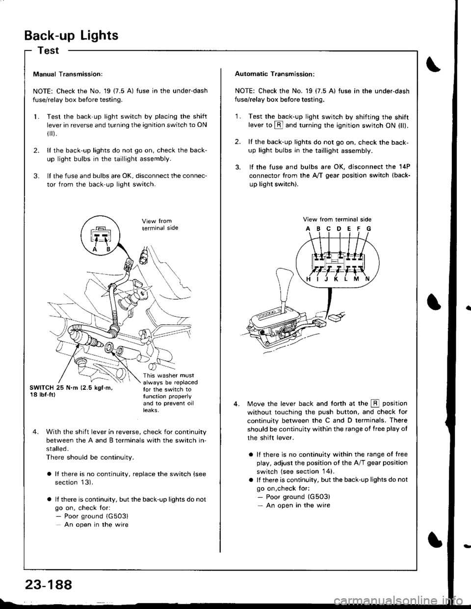
Manual Transmission:
NOTE: Check the No. 19 (7.5 A) fuse in the underdash
fuse/relay box before testing.
Test the back-up light switch by placing the shift
lever in reverse and turning the ignition switch to ON
fl r).
lI the back-up lights do not go on, check the back-
up light bulbs in the taillight assembly.
lI the fuse and bulbs are oK, disconnect the connec-
tor from the back-up light switch.
2.
3.
l.
SWITCH 25 N.m (2.5 kgf-m,'18 lbf-Ir)
This washer mustalways be replacedfor the switch totunction properly
and 10 prevent oilteaKs,
terminal side
4. With the shift lever in reverse, check for continuity
between the A and B terminals with the switch in-
stalled.
There should be continuity.
a It there is no continuity, replace the switch (see
section 13).
a lf there is continuity, but the back-up lights do not
go on, check for:- Poor ground {G503}
An open in the wire
A
6
Automatic T.ansmission:
NOTE: Check the No. 19 (7.5 A) fuse in the under-dash
fuse/relay box before testing.
2.
'1 .Test the back-up light swirch by shifting the shiftlever to @ and turning the ignition switch ON (ll).
lf the back-up lights do not go on, check the back-
up light bulbs in the taillight assembly.
lf the fuse and bulbs are OK, disconnect the 14P
connector from the A,/T gear position switch (back-
up light switch).
View from terminal side
ABCDEFG
Move the lever back and torth at the E position
without touching the push button, and check for
continuity between the C and D terminals. There
should be continuity within the range of free play of
the shilt lever.
a lf there is no continuity within the range of free
play, adiusl the position ot the A/T gear position
switch {see section 14}.
a lf there is continuity, but the back-up lights do not
go on,check tor:- Poor ground {G5O3)- An open in the wire