1998 HONDA INTEGRA lock
[x] Cancel search: lockPage 322 of 1681

Before connecting a new fuel tube/quick-connect fitting
assembly, remove the old retainer from the mating pipe.
With rhetabs pulled
apart, Pullthe retaineroff
New FUEL TUBE/OUICK.CONNECTFTflNG ASSEMBLY
3. Align the quick-connect fittings with the pipe, and
align the retainer locking pawls with the connector
grooves. Then press the quick connect fittings onto
the pipe until both retainer pawls lock with a click-
Ing souno.
NOTE: lf it is hard to connect, put a small amount of
new engine oil on the pipe end.
Connection with new retainer:
5.
Make sure the connection is secure and the pawls
are lirmly locked into place; check visually and by
pulling the connector.
RETAINER
Reconnect the battery negative cable, and turn the
ignition switch ON (ll) the fuel pump wjll run for about
two seconds, and fuel pressure will rise. Repeat two
or three times, and check that there is no leakage in
the fuel supply system.
11-117
Page 335 of 1681

l-
Intake Air System
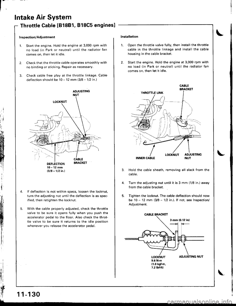
LOCKNUT
DEFLECTION10-12mmBIA- 112in.l
lf deflection is not within specs, loosen the locknut,
turn the adjusting nut until the deflection is as spec-
ified, then retighten the locknut.
With the cable properly adiusted, check the throttle
valve to be sure it opens fully when you push the
accelerator pedal to the floor. Also check the throt-
tle valve to be sure it returns to the idle position
whenever you release the accelerator pedal.
Throttle Cable IB18B1, 818C5 engines]
Inspection/Adiustment
1. Start the engine. Hold the engine at 3,000 rpm wirh
no load (in Park or neutral) until the radiator tan
comes on, then let it idle.
2. Check that the throttle cable operates smoothly wilh
no binding or sticking. Repair as necessary.
3. Check cable free play at the throttle linkage. Cable
deflection should be 10 - 12 mm (3/8 - 'l12 in.l
ADJUSTINGNUT
t
il
qr
ll1 1-130
!!
TING NUT
\lnstallation
1. Open the throttle valve fully, then install the throttle
cable in the throttle linkage and install the cable
housing in the cable bracket.
2. Start the engine. Hold the engine at 3,000 rpm with
no load (in Park or neutral) until the radiator fan
comes on, then let it idle.
INNER CABLE
Hold the cable sheath, removing all slack from the
caote.
Turn the adjusting nut until it is 3 mm {1/8 jn.) away
from the cable bracket.
Tighten the locknut, The cable deflection should now
be 10 - '12 mm (3/8 - 'll2 in.). lf not, see Inspection/
Adjustment.
3 mm 10.12 inl
u
4.
AD
\
JUSLOCKNUT9.8 N.m(1.0 kgt.m,7,2lbl.ttl
CABI.E
CABI,E BMCKET
Page 336 of 1681

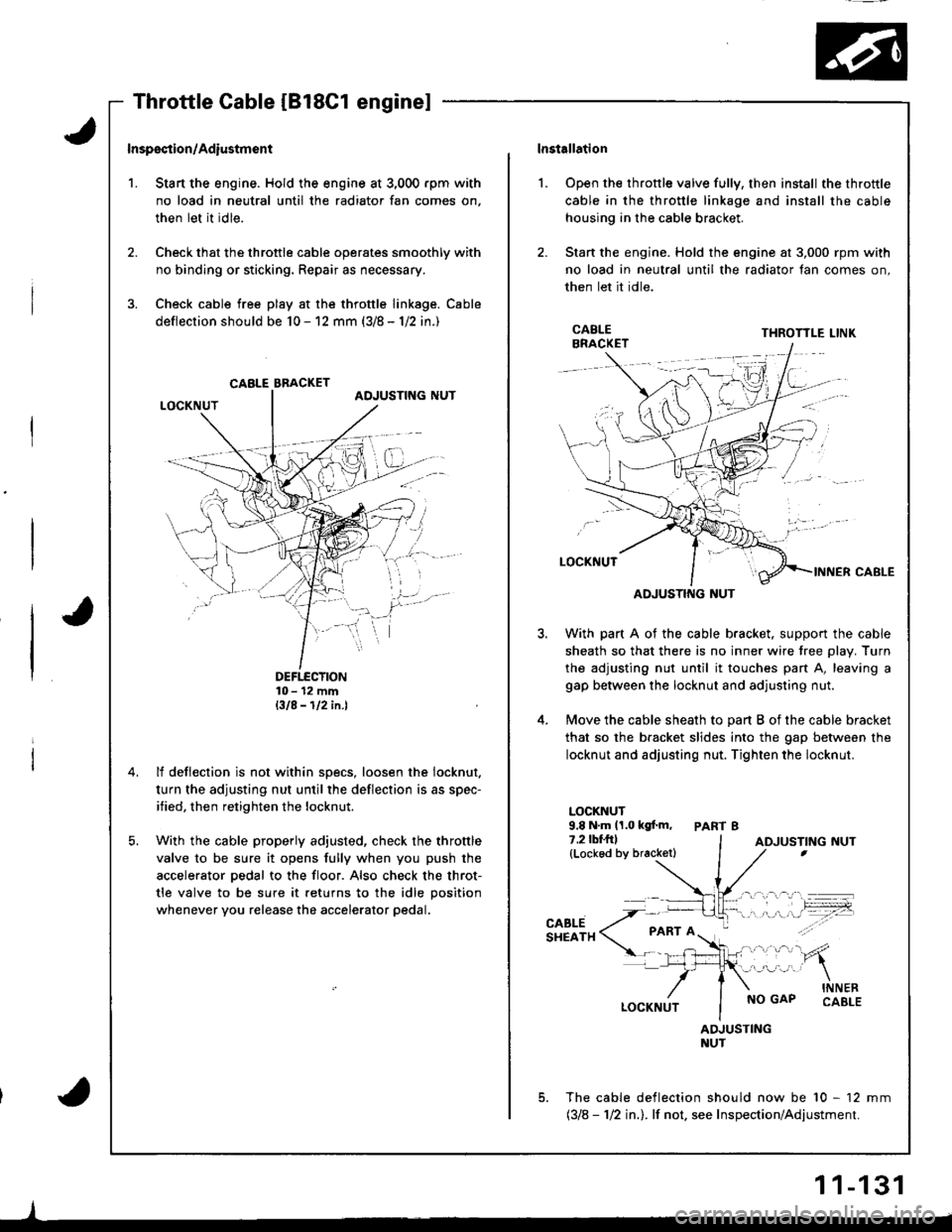
't.
Inspsction/Adiustmsnt
Stan the engine. Hold the engine at 3,000 rpm with
no load in neutral until the radiator fan comes on,
then let it idle.
Check that the throttle cable operates smoothly with
no binding or sticking. Repair as necessary.
Check cable free play at the throttle linkage. Cable
deflection should be 10 - 12 mm (3/8 - 1/2 in.)
DEFTECTION10- 12 mmBIA-112in.l
lf deflection is not within specs, loosen the iocknut.
turn the adjusting nut until the deflection is as spec-
ified, then retighten the locknut.
With the cable properly adjusted, check the throttle
valve to be sure it opens fully when you push the
accelerator pedal to the floor. Also check the throt-
tle valve to be sure it returns to the idle position
whenever you release the accelerator pedal.
CABLE BBACKET
lnstallation
Open the throttle valve fully, then install the throttle
cable in the throttle linkage and install the cable
housing in the cable bracket.
Stan the engine. Hold the engine at 3,000 rpm with
no load in neutral until the radiator fan comes on,
then let it idle.
l.
3.
5.
CABLEBRACKETTHROTTLE LINK
ADJUSTING NUT
With part A of the cable bracket. support the cable
sheath so that there is no inner wire tree plav. Turn
the adjusting nut until it touches part A, leaving a
gap between the locknut and adjusting nut.
Move the cable sheath to oart B of the cable bracket
that so the bracket slides into the gap between the
locknut and adjusting nut. Tighten the locknut.
LOCKNUT9.8 N.m 11.0 kgf.m, PART 87.2lbf.frl(Lockod by bracketl
CABLESHEATH
NO GAPINNERCABLE
ADJUSTINGNUT
The cable deflection should now be 10 - 12 mm(318 - 112 in.l. lf not. see Inspection/Adjustment.
ADJUSTING NUT
1 1-131
Page 340 of 1681

Troublsshooting
IAB CONTROLDIAPHRAGM
Inapection ot IAB Control System.
Chack {or vacuum at idle:1. Stan the engine and allow itto idle.2. Romove the vacuum hose fromthe IAB control diaphragm andconnect vacuum gauge to thenose,
Check to. vacuum at IAB vacuumttnl;Remove No. 13 vacuum hose fromthe IAB vacuum tank, then checkfor vacuum at the IAB vacuumtank.
Repair th€ blockage or vacuuml6ak between the IAB vacuumtenk 6nd the intake manifold.
Check for an open in the wirellAB SOL line):1. Turn the ignition switch OFF.2. Disconnect the IAB controlsolenoid valve 2P connector.3. Turn the ignition switch ON (ll).4. Measure vohage between theIAB control solenoid valve 2Pconnector terminals No, 1 andNo.2.
ls there battery voltage?
Chack for rn op€n or 3hort in thewire (lAB SOL line):Measuro voltage between bodyground and the IAB controlsolenoid valve 2P connector termi-nai No. 1.
IAB SOL(RED/BLUI
rt./; Ir I-TD,2F-' Y\.\/ | ]IGND(BLKI
Wire side ot female terminals
IAB CONTROL SOLENOIDVALVE 2P CONNECTOR {C134)
IAB SOLIRED/BLU)
(cont'd)
11-135
(To page I'l-136)(To page 11.136)
Page 353 of 1681

Emission Control System
Check the vacuum when hot:1. Turn the ignition switch OFF.2. Block the rear wheels and setthe parking brake.3. Jack up the front of the vehi-cle and support it with safetystands.4- Start the engine. Hold theengine at 3,000 rpm with noload (in Park or neutral) untilthe radiator fan comes on, thenlet it idle.5. Check for vacuum at the vacuum hose with transmissionin gear (A/T in E position,M/T in 'l st gear) after startingrne engrne.6. Ouickly raise the engine speedto 3,000 rpm.
Evaporative Emission (EVAP) Controls (cont'd)
(From page 1'l 147)Check the EVAP purge controlsolenoid valve:1. Disconnect the 2P connectorfrom the EVAP purge controlsolenoid valve.2. Ouickly raise the engine speedto 3,000 rpm.
{To page 11 149)
tfl'I
Check lor a short in the wire{PCS line}l1. Turn the ignition switch OFF.2. Disconnect ECM connector A(32P).
3. Check for continuity betweenthe EVAP purge control solenoid valve 2P connector termi-nal No. 2 (818C5 engine: No. 1)and body ground.
Check for an open in the wire llclline):1. Turn the ignition switch OFF.2, Disconnect the 2P connectorfrom the EVAP purge controlsolenoid valve.3. Turn the ignition switch ON (ll).
4. At the harness side, measurevo ltage between the EVAPpurge controlsolenoid valve 2Pco n nector terminal No. 1( B 18C5 engine: No. 2) andbody ground.
EVAP PURGE CONTROI SOLENOIDVALVE 2P CONNECTOR IC114)B18C1, Cl8Bl engines: 818C5 engine:
PCSIRED/YEL}
femaleWire side offemaleterminals
YES
IGPl{YEL/BLKI
IGPlIYEL/BLKI
ECM CONNECTOR A {32PIPG1IBLKI
Insp€ct vacuum hose routing.lf OK, replace the EVAP purge
control solenoid valve.
neDair short in the wire betweenthe EVAP purge control solenoidvalve and the ECM lAl5).
Substitute a known-90od ECMand recheck. lI symptom/indica-tion goes away, replace the origi-nal ECM.
Repair open in the wirc betweenEVAP purge control solenoidvalve and PGM-FI main relav fuse.ls there battery voltage?
Check for an open in the wireIPCS linel:1. Turn the ignition switch OFF.2. Reconnect the 2P connector tothe EVAP purge control sole'noid valve.3. Turn the ignition switch ON (ll).
4. Measure voltage betweenECM connector terminals A15and A10.
Bopair open in the wiro betweenthe EVAP purgo control 3olanoidvalvo and the EcM {415).
11-144
(To page 11-149)
Page 361 of 1681

Clutch Pedal
Adjustment
NOTE:
a To check the clutch interlock switch and clutch
switch, see section 23.
a The clutch is self-adjusting to compensate Ior wear.
CAUTION: ll there is no clealance between the master
cylinder piston and push rod, the release bearing is held
against the diaphragm spring, which can result in clutch
slippage or other clutch problems.
1. Loosen locknut A, and back off the clutch switch
(or adjusting bolt) until it no longer touches the clutch
peoal.
2. Loosen locknut C. and turn the push rod in or out
to get the specified stroke (@) and height {O) at the
clutch Dedal.
3. Tighten locknut C.
4. Turn the clutch switch (or adjusting bolt) until it con-
tacts the clutch pedal.
ASSIST SPRING
@{
{PiN 08798-9002t
(STROKE at PEDAL): 130-140 mm (5.12-5.51 in){TOTAL CLUTCH PEDAI- FREE PLAYI: 12-21 mm (0.47-0.83 inl including tho p6dal play{CLUTCH PEDAL HEIGHT): 164 mm 16.46 inl to the tloor(CLUTCH PEDAL DISENGAGEMENT HEIGHTI: 83 mm {3.27 inl minimum to the floo.
t?
5.Turn the clutch switch (or adjusring bolt) in 3/4 to
1 full turn further.
Tighten locknut A.
Loosen locknut B on the clutch interlock switch.
Measure the clearance between the floor board and
clutch pedal with the clutch pedal tully depressed.
Release the clutch pedal 15-20 mm (O.59-O.79
in) from the fully depressed position and hold it there.
Adjust the position of the clutch interlock switch so
that the engine will stan with the clutch pedal in this
position.
Turn clutch interlock switch 3/4 to 1 full turn further.
Tighten locknut B.
9.
6.
7.
8.
10.
11.
LOCKNUT B9.8 N.m 11.0 kgt.m, 7 lbl.ft)
CLUTCH INTERLOCKswrTcHPUSH ROD
CLUTCH MASTER CYLINDER
CLUTCH SWITCH(or AOJUSTING BOLT)
LOCKNUT A9.8 N.m (1.0 kgf.m, 7 lbt.frl
l
{P/N 0879a-9002)
12-4
1- 10 mm (0.O4-O.39 inl
Page 373 of 1681

Transmission Assembly
Removal
r@i Make surs iacks and safety stands sro placod propor-
ly (3ee s€ction 1).
. Apply parking brake and block resr whaeb 30 vohicle
will not roll off stands and hll on You whil6 working
under it.
CAUTION: Use fender covers to svoid damaging
paintod surtacos.
1. Disconnect the negative (-) cable from the battery,
then the positive {+) cable.
2. Remove the intake 8ir duct and the air cleaner hous-
ing assembly,
AIR CLEANERHOUSINGASSEMBL
Disconnect the back-up light switch connector and
the transmission ground wire.
BACK.UP LIGHTSWITCH CONNECTOR
TRANSMISSIONTRANSMISSIO
GROUND WIRE HANGEB B
4. Remove tne lowei radiator hose"clamp from the
transmission hsnger B.
INTAKE AIR DUCT
13-4
\-
5. Remove the wire hsrness clamps.
VSS CONNECTOR
Disconnect the starter motor cables and the vehicle
speed sensor (VSS) connector.
Remove the clutch pipe bracket and the slave cylin-
der.
NOT€: Do not operate the clutch pedsl once the
slave cvlinder has been removed.
7.
Page 379 of 1681

Change Holder Assembly
Clearance Inspection
Measure the clearance betwe€n the shift Diece and
the shift arm holder.
Standard: 0.1 - 0.3 mm (0.004 - 0.012 inl
Servico Limit: 0.6 mm (0,02 inl
lf the clearance is more than the service limit, mea-
sure the width of the groove in the shift piece.
Standard: 8.1 - 8.2 mm (0.319 - 0.323 in)
. lf the width of the groove is not within the stan-
dard, replace the shift piece with a new one.. lf the width of the groove is within the standard,
replace the shift arm holder with a new one.
SHIFT PIECE
t.-_
O
SHIFT ARM HOLDER
SHIFT PIECE
Measure the clearance between the select arm
the interlock.
Standard: 0.05 - 0.25 mm (0.002 - 0.010 in)
Service Limit:0.5 mm {0.02 inl
and
INTERLOCK
lf the clearance is more than the service limit, mea-
sure the width of the interlock,
Standard: 9.9 - 10.0 mm 10.390 - 0.394 in)
. lf the width is not within the standard. replace
the interlock with a new one.. lf the width is wilhin the standard replace the
select arm with a new one.
(cont'd)
13-13