Page 1504 of 1681

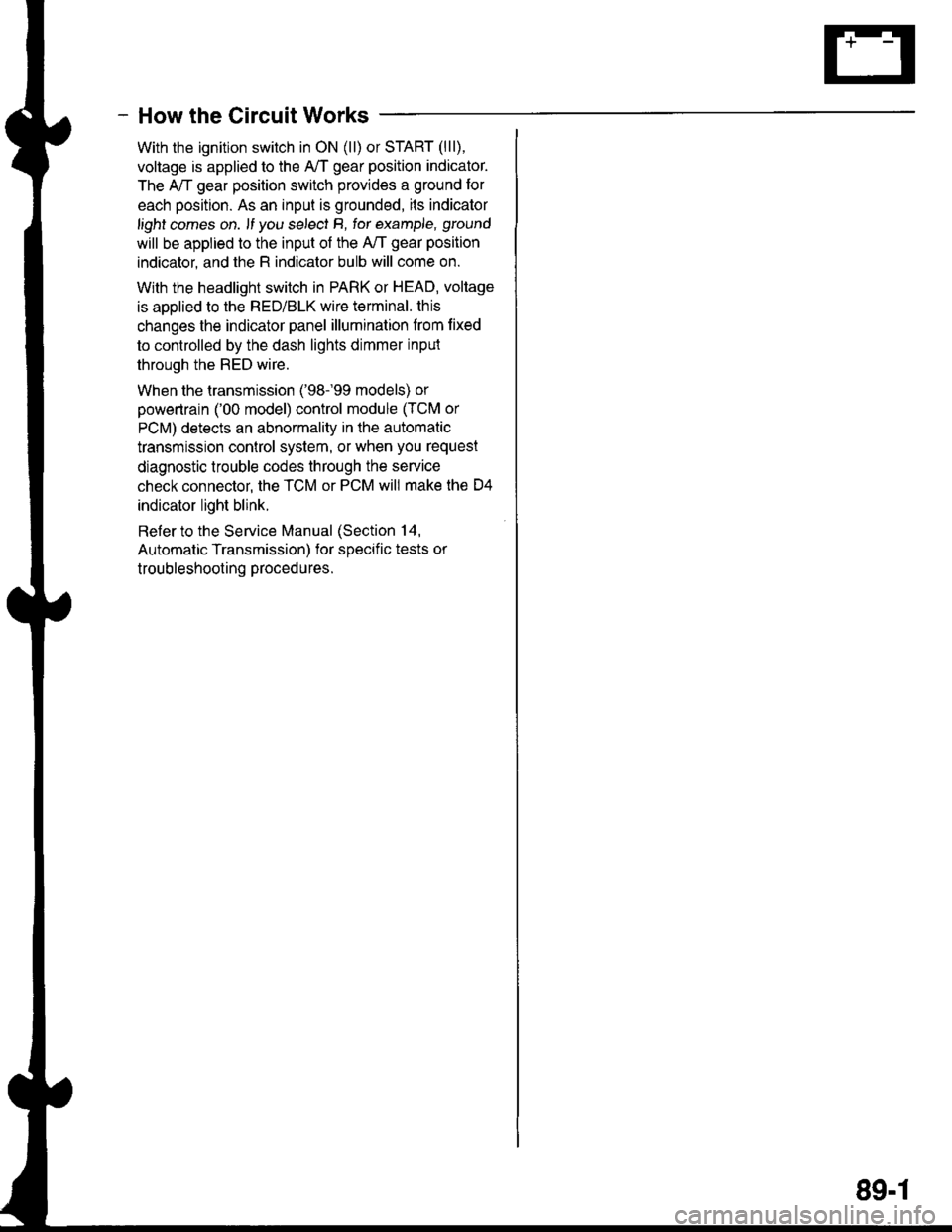
- How the Circuit Works
With the ignition switch in ON (ll) or START (lll),
voltage is applied to the A,/T gear position indicator.
The A,/T gear position switch provides a ground for
each position. As an input is grounded, ils indicator
light comes on. lf you se,ecl B, tor example, ground
will be applied to the input of the A,/T gear position
indicator, and the R indicator bulb will come on.
With the headlight switch in PARK or HEAD, voltage
is applied to the RED/BLK wire terminal. this
changes the indicator panel illumination from lixed
to controlled by the dash lights dimmer inpul
through the RED wire.
When the lransmission ('98.�99 models) or
powertrain ('00 model) control module (TCM or
PCM) detects an abnormality in the automatic
transmission control system, or when you request
diagnostic trouble codes through the service
check connector, the TCM or PCM will make lhe D4
indicator light blink.
Refer to the Service Manual (Section 14,
Automatic Transmission) for soecific tests or
troubleshooting procedures.
89-1
Page 1513 of 1681
Back-up Lights
-.I UNDER.DASH
I I ruSr rs I FUSETRELAY
| ! 1;" ," uo"'. I F"?T" *
I i- |L-J-----J'o Y "c,fl13.,YEL I YEL s€e powsr
a- Distribution,
- Hatchback
Automatic Transmission
page 10-4.
l\4anual Transmission
*'l
A/T GEARPOSITIONswtTcH
.=L=r-.
!"1"''1,!
.frl_.j
Io
BLKYeLr
I.II-II'
"Tt
"*,
erx I eaoro roa
arrrr-<
"'i
U "ro'':;^::;:"
"""1:i*#J;;;"
r# aacr-upI 1 | LrcHT swrrcH
I t _ | l]"^#1,;:. tra.lsm,ss,on
o"n,".*F "noto t'
","'"J, fi ";o'8"
""",J; fi F;%,,
"""JIft 9,:%,,
""-".t- [
t*'
fi f,f.l,l" "onn"",o.,
*" *_
I ilil,?:lli 0,"""",
o"n".*!ffi;-'l
,lF;,;,,,
:l::. ,fffi:,*
canre.*l i$itdq o"n".*f
@ l.:{;*-," ""g#'"'c'o*
@
g.[H,,.
rt
IA
F
I
See GroundDistribution,page 14-7.
G503
"Tt
"u,.
au I Puoto 'oe
Frrrrra
110
BLK
Page 1514 of 1681
- Sedan
Automatic Transmission
:ibi"lf:li::",""
I
I
I
I
.$t=t
i " j'*'-1,
| " &---? ar
",::i'*
'
A/T GEARPOStTtONSWITCH
3 .i c422
n"n,".^ |
"'oto'u
* tf-l:" "o"""",o,,
o"n,".^
! il?,l?lli o'""""'
o"n ur* | o"n ".* [
o"*"*
|
t *"";%,,, u l"uro ...^.lln*,,,cn,r ar-x .ff
-"" " '"
Hl+irT" GRN 8tx )t
@i[r"t"
coNNtcroR
Qphft,"
".*f af,,. - see crou!.c
"*!#
a-< Distribution, _.._ I"ri:3rr:''*sr ri;;;'l
^:"Y9;%,,, ".^| """'
s€ecround
:---< 3lflit8:'
G503PHO|O 102
'i[,rr*,'
i,!,.1t;"%""
o"",".?frFH''Ffi elcr.up
| | r-rcxr swncx
I t_rl fi,ffi$#1, transm'ssion
o"n,".*F "'oto oo
*",Jf, F;0,3,"
""",Jlt "";t%,.
""""'Jf "";%"
110-1
Page 1569 of 1681
Component Location
b-
13. Right Front Corner of Engine Compartment16. Right Side of Engine (GS-R Shown, Others Similar)
14. Top Front of Manual Transmission17. Right Side of Engine (All Except GS-R)
15, Top Front ot Automatic Transmission18. Right Side of Engine (GS-R)
l201-2
Page 1571 of 1681
25. Top Rear of Automatic Transmission ('98-'99 Mod.)
Component Location
\
28. Right Side of Engine
26. Too Rear ot Transmission29. Center Rear of Engine (Type-R)
27 . Lower Right Side of Engine Compartment30. Center Rear of Engine (All Except GS-R)
201-4
Page 1632 of 1681

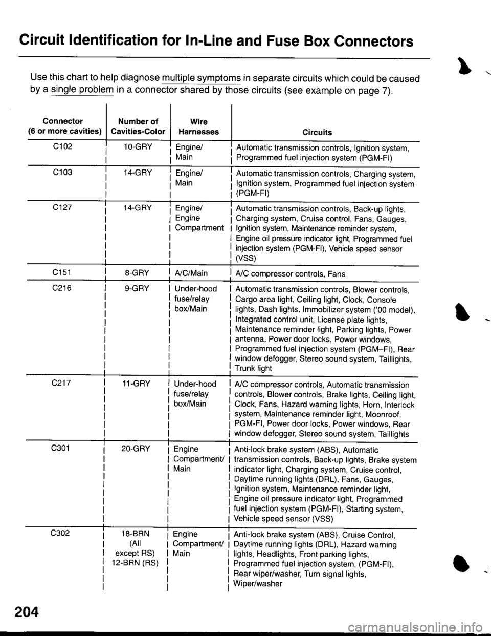
Circuit ldentification for In-Line and Fuse Box Connectors
Use this chart to help diagnose multiple symptoms in separate circuits which could be caused
by a single problem in a connector shared by those circuits (see example on page 7).
Connector
(6 or more cavities)
Number of
Cavities-Color
Wire
Harnesses
Engine/
Main
Engine/
Engine
Compartment
I Automatic transmission controls, lgnition system,
i Programmed fuel injection system (PGM-F|)
Automatic transmission controls, Charging system,
lgnition system, Programmed fuel injection system(PGM-FI)
Automatic transmission controls, Back-up lights,
Charging system, Cruise control, Fans, Gauges,
lgnition system, Maintenance reminder system,
Engine oil pressure indicator light, Programmed fuel
injection system (PGM-Fl), Vehicle speed sensor
ffss)
| {c/Main! A,/C compressor controls, Fans
Under-hood
fuse/relay
box/Main
Automatic transmission controls, Blower controls,
Cargo area light, Ceiling light, Clock, Console
lights, Dash lights, lmmobilizer system ('00 model),
Integrated control unit, License plate lights,
Maintenance reminder light, Parking lights, Power
antenna, Power door locks, Power windows,
Programmed fuel iniection system (PGM-Fl), Rear
window defogger, Stereo sound system, Taillights,
Trunk lioht
11-GRY
18-BBN
(4il
except BS)
12-BBN (RS)
Under-hood
fuse/relay
box/Main
Engine
CompartmenV
Main
Engine
CompartmenU
Main
lr,/C compressor controls, Automatic transmission
controls, Blower controls, Brake lights, Ceiling light,
Clock, Fans, Hazard warning lights, Horn, Interlock
system, Maintenance reminder light, Moonroof ,PGM-FI, Power door locks, Power windows, Rear
window defogger, Stereo sound system, Taillights
Anti-lock brake system (ABS), Automatic
transmission controls, Back-up lights, Brake system
indicator light, Charging system, Cruise control,
Daytime running lights (DRL), Fans, Gauges,
lgnition system, Maintenance reminder light,
Engine oil pressure indicator light, Programmed
tuel injection system (PGM-F|), Starting system,
Vehicle speed sensor (VSS)
Anti-lock brake system (ABS), Cruise Conkol,
Daytime running lights (DRL), Hazard warning
lights, Headlights, Front parking lights,
Programmed fuel injection system, (PGM-Fl),
Rear wiper/washer, Turn signal lights,
Wiper/washer
204
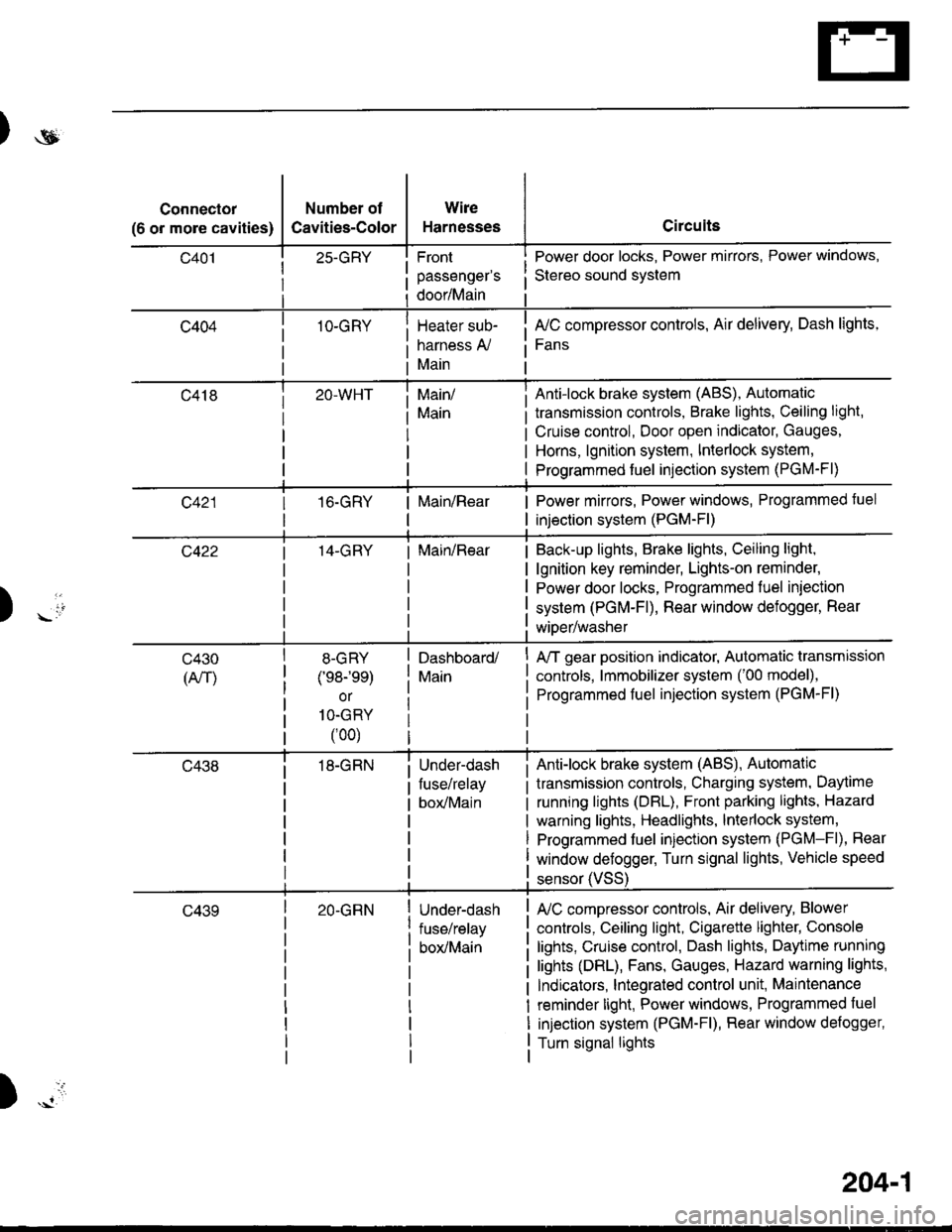
Page 1633 of 1681

)ot
Connector
(6 or more cavities)
Number of
Cavities-Color
25-GRY
1O-GRY
Wire
Harnesses
Front
passenger's
door/Main
Heater sub-
harness A,/
Main
Circuits
Power door locks, Power mirrors, Power windows,
Stereo sound svstem
fuC compressor controls, Air delivery, Dash lights,
Fans
transmission controls, Brake lights, Ceiling light,
Cruise control, Door open indicator, Gauges,
Horns, lgnition system, Interlock system,
Programmed fuel injection system (PGM-Fl)
Main/
Main
Anti-lock brake system (ABS), Automatic
16.GRYMain/RearPower mirrors, Power windows, Programmed tuel
injection system (PGM-Fl)
14-GRYMain/RearBack-up lights, Brake lights, Ceiling light,
lgnition key reminder, Lights-on reminder,
Power door locks, Programmed fuel iniection
system (PGM-Fl), Rear window defogger, Rear
wiDer/washer) -io
tl
c430
(An)
8-GRY
(e8-'ee)
or
1O-GRY
(00)
18-GRN
Dashboard/
Main
Under-dash
fuse/relay
box/Main
A/T gear position indicator, Automatic transmission
controls, lmmobilizer system ('00 model),
Programmed fuel injection system (PGM-Fl)
Anti-lock brake system (ABS), Automatic
transmission controls, Charging system, Daytime
running lights (DBL), Front parking lights, Hazard
warning lights, Headlights, lnterlock system,
Programmed fuel injection system (PGM-Fl), Rear
window defogger, Turn signal lights, Vehicle speed
c43920-GRNUnder-dash
fuse/relay
box/Main
sensor (VSS
L/C compressor controls, Air delivery, Blower
controls, Ceiling light, Cigarette lighter, Console
lights, Cruise control, Dash lights, Daytime running
lights (DRL), Fans, Gauges, Hazard warning lights,
Indicators, lntegrated control unit, Maintenance
reminder light, Power windows, Programmed fuel
injection system (PGM-Fl), Rear window defogger,
Turn signal lights
)
204-1
Page 1638 of 1681

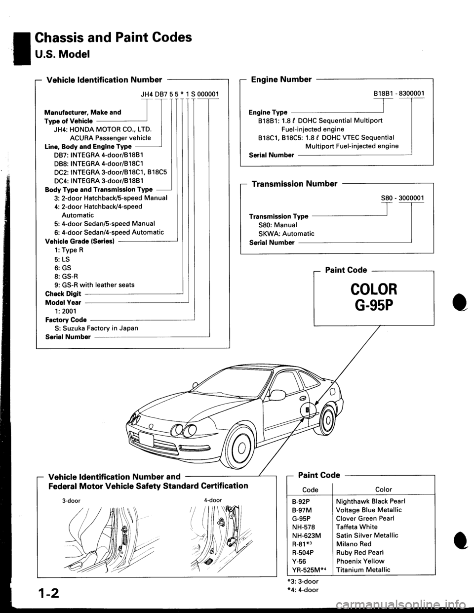
JH4DB755*1S000001
JH4: HONDA MOTOR CO., LTD.
ACURA Passenger vehicle
Line, Body and Engine Type
DB7: INTEGRA 4-door/81 881
DB8: INTEGRA 4-door/B1 8C1
DC2: INTEGRA 3-door/818C1, 818C5
DC4: INTEGRA 3-door/B1881
Body Type and Transmission Type
3: 2-door Hatchback/5-speed Manual
4: 2-door Hatch back/4-speed
Automatic
5: 4-door Sedan/S-speed Manual
6: 4-door Sedan/4-speed Automatic
9: GS-R with leather seats
S: Suzuka Factory in Japan
! Chassis and Paint Codes
I U.S. Model-
Vehicle ldentification Number and
Federal Motor Vehicle Safety Standard Certification
4-door
Paint Gode
COLOR
G-95P
'#19
'//dt
+3: 3-door*4: 4-door
81881
818B1: 1.8 f DOHC Sequential Multiport
Fuel-injected engine
818C1, 818C5: 1.8 f DOHC WEC Sequential
Multiport Fuel-injected engine
Paint Code
Nighthawk Black Pearl
Voltage Blue Metallic
Clover Green Pearl
Taffeta White
Satin Silver Metallic
Milano Red
Ruby Red Pearl
Phoenix Yellow
Titanium Metallic
B-92P
B-97M
G-95P
NH-578
NH-623M
R-81*3
R-504P
Y-56
YR-525M*4
1-2
./.4r//.'.