Page 1077 of 1681
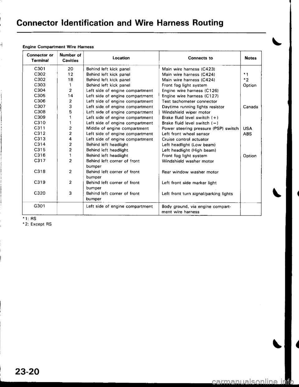
Connector ldentification and Wire Harness Routing
Engine Compartment Wire Halness
nll
Connectoa ot
Terminal
Number of
CavitiesLocationConnects toNotes
c301
c302
c 302
c303
c304
c306
c307
c308
c309
c310
c3l 1
c312
c314
c316
c317
c318
c319
c320
20
't8
1
14
2
3
5
1
1
2
2
4
2
2
1
2
2
2
3
Behind left kick panel
Behind left kick panel
Behind left kick panel
Behind left kick panel
Lett side of engine compartment
Lett side of engine companment
Lett side of engine compartment
Left side of engine compartment
Left side of engine compartment
Left side of engine compartment
Left side of engine compartment
Middle of engine compartment
Lett side of engine companment
Left side of engine compartment
Behind left headlight
Behind left headlight
Behind left headlight
Behind left corner of front
DUmper
Behind left corner ol front
bumper
Behind lett corner of front
bumper
Behind left co.ner of lront
bumper
Main wire harness (C423)
Main wire harness {C424)
N4ain wire harness (C424)
Front fog light system
Engine wire harness (C126)
Engine wire harness (C'127)
Test tachometer connector
Daytime running lights resistor
Windshield wiper motor
Brake f luid level switch (+ )
Brake f luid level switch ( - )
Power steering pressure (PSP) switch
Lett front wheel sensor
Cruise control actuator
LeIt headlight (Low beam)
Lett headlight {High beam)
Front fog light system
Windshield washer motor
Rear window washer motor
Left front side marker light
Left front turn signal/parking lights
Option
Canada
USA
ABS
Option
G301Lelt side of engine compartmentBody ground, via engine compart-
ment wire harness
23-20
Page 1130 of 1681
;
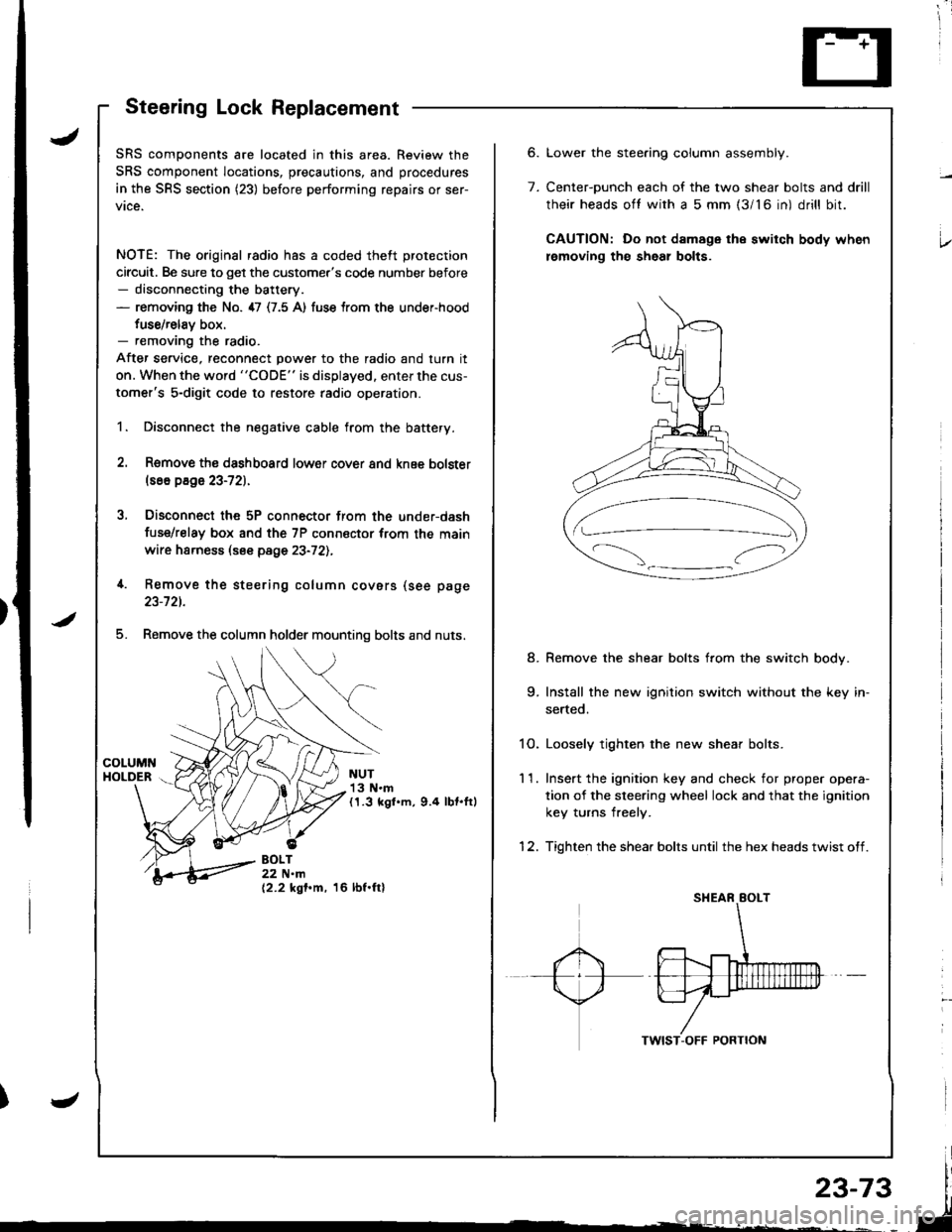
Steering Lock Replacement
SRS components are located in this area. Review the
SRS component locations, precautions, and procedures
in the SRS section (23) before performing repairs or ser-
vice.
NOTE: The original radio has a coded theft protection
circuit. Be sure to get the customer's code number before- disconnecting the battery.- removing the No. 47 (7.5 A) fuse trom the under-hood
fuse/relav box.- removing the radio.
After service, reconnect power to the radio and turn it
on. When the word "CODE" is displayed. enter the cus-
tomer's 5-digit code to restore radio operation.
1. Disconnect the negative cable from the battery.
2. Remove ths dsshboard lower cover and knee bolster(s6o p8ge 23-72).
3, Disconnect the 5P connector from the under-dash
fuse/relay box and the 7P connsctor from th€ main
wire harness (see page 23-72l.,
4. Remove the steering column covars (see page
23-721.
5. Remove the column holder mounting bolts and nuts.
NUT13 N.m(1.3 kgl.m, 9.4 lbt.ftl
BOLT22 N.m(2.2 kgf.m, 16 lbf.ftl
6.
7.
Lower the stee.ing column assembly.
Center-ounch each of the two shear bolts and drill
their heads oft with a 5 mm {3/16 in) drill bit.
CAUTION: Do not damage the switch body when
lemoving th€ sheal bolts.
Remove the shear bolts from the switch body.
Install the new ignition switch without the key in-
serted.
1O. Loosely tighten the new shear bolts.
11. Ins€rt the ignition key and check for proper opera-
tion of the sleering wheel lock and that the ignition
key turns freely.
12. Tighten the shear bolts until the hex heads twist off.
8.
Page 1183 of 1681
1.
2.
Gauge Assembly
Removal
Remove the two screws from the instrument panel.
Remove the instrument panel.
NOTE: Remove the instrument panel carefully
without damaging the clips.
23-126
3.
5.
Tilt the steering wheel down with the tilt adjustment
lever.
Remove the three mounting screws, and spread a
protective cloth on the steering column.
PROTECTIVE CLOTH
Pry the gauge assembly out, and disconnect all con
nectors from it.
6:
GAUGE ASSEMBLY
Take out the gauge assembly as shown.
GAUGE ASSEMBLY
Page 1266 of 1681
SwitchTest
SRS comDonents are located in this area. Review the
SRS component locations, precautions, and procedures
in the SRS section (23) before performing repairs or ser-
vtce.
NOTE: The original radio has a coded thett protection cir-
cuit. Be sure to get the customer's code number beJore- disconnecting the battery.- removing the No. 47 (7.5 A) fuse from the under-hood
fuse/relay box.- removing the radio.
After service, reconnect Dower to the radio and turn it on.
When the word "CODE" is displayed, enter the customer's
5-digit code to restore radio operation
Disconnect the battery negative cable, then discon-
nect the positive cable, and wait at least three min-
uIes.
Disconnect each airbag connector.
Driver's Side:
a Remove the access panel from the steering wheel,
then disconnect the 2P connector between the
driver's airbag and cable reel.
Front Passenger's Side:
. Remove the glove box,
a Disconnect the 2P connector between the front
passenger's airbag and SRS main harness.
1.
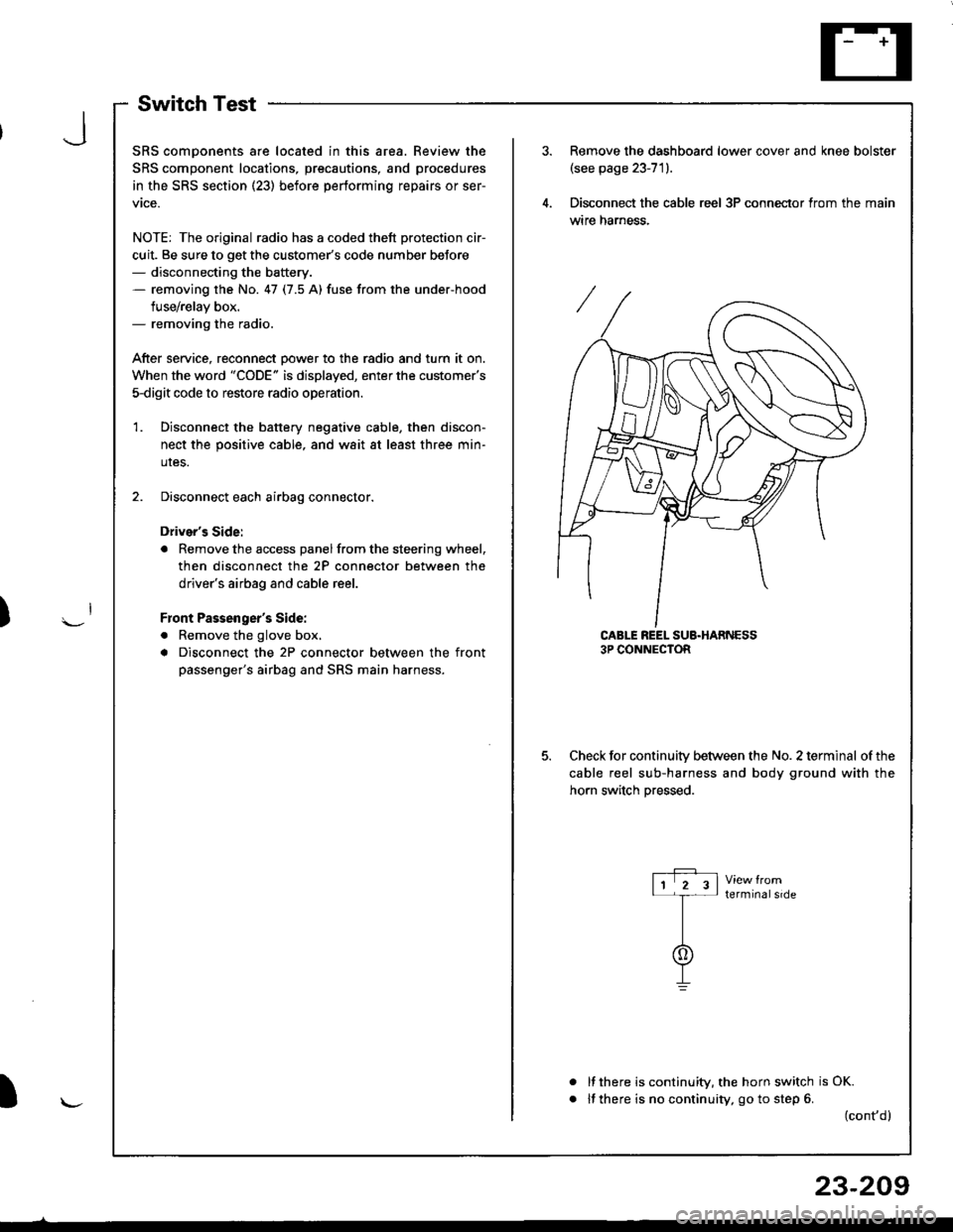
Remove the dashboard lower cover and knee bolster(see page 23-71).
Disconnect the cable reel 3P conneclor from the main
wtre narness.
CABLE REEL SUB.HARNESS3P CONNECTOR
Check for continuitv between the No. 2 terminal of the
cable reel sub-harness and body ground with the
horn switch Dressed.
terminalside
a
It there is continuity, the horn switch is OK.
lf there is no continuity, go to step 6. (cont,d)
r-P r11 2 3l-t-
I
I\-J
)
I
23-209
Page 1267 of 1681
Horn
Switch Test (cont'd)
Remove the driver's airbag assembly (refer to the
SRS sub-section in section 23).
Check for continuity between the No. 2 terminal of
the cable reel sub-harness 3P connector and horn
Dositive terminal.
lf there is no continuity. replace the cable reel.
lf there is continuity, replace the horn switch.
a
a
HORN POSITIVE TERMINAL
23-210
9.
10.
11.
12.
lf all tests prove OK, reinstall the driver's airbag
assembly (re{er to the SRS sub-section in section 23).
Reconnect the driver's airbag connectors, and rein-
stall the access panel on the steering wheel.
Reconnect the front passenger's airbag connector,
and reinstall the glove box.
Connect the battery positive cable, then connect the
negative cable.
Atter installing the airbag assembly, confirm that
- the SRS indicator light should come on for about
six seconds and then go off with the ignition switch
oN 0t).- the horn sounds with the horn button pressed.
Page 1314 of 1681
Set/Resume Switch Test/Replacement
SRS comDonents are located in this area. Review the
SRS component locations, precautions, and procedures
in the SRS section (23) before performing repairs or ser-
vice.
NOTE: The original radio has a coded theft protection cir-
cuit, Be sure to get the customer's code number before- disconnecting the battery.- removing the No. 47 {7.5 A} fuse from the under-hood
fuse/relav box.- removing the radio.
Atter service, reconnect Dower to the radio and turn it on.
When the word "CODE" is displayed, enter the customer's
s-digit code to restore radio operatior..
1. Disconnect the battery negative cable, then discon-
nect the oositive cable, and wait at least three min-
utes,
2. Disconnect each airbag connector.
Drivor's Side:
a Remove the access panel from the steering wheel,
then disconnect the 2P connector between the
driver's airbag and cable reel,
Front Passenge;'s Side:
a Remove the glove box.
. Disconnect the 2P connector between the front
passenger's airbag and SRS main harness.
)
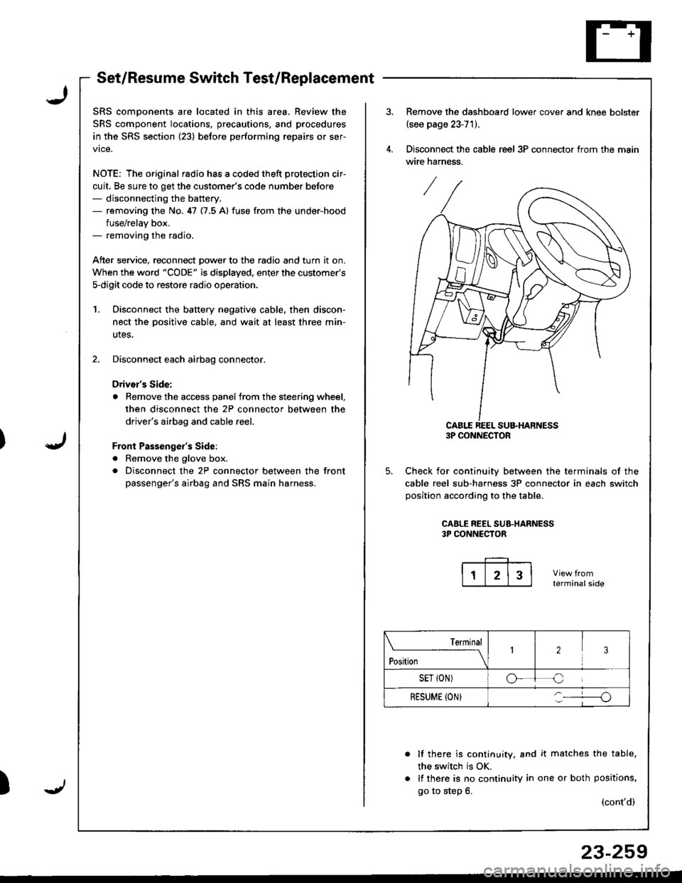
Remove the dashboard lower cover and knee bolster(see page 23-71).
Disconnect the cable reel 3P connector trom the main
wire harness.
CABLE REEL SU&HARNESS3P CONNECTOR
Check for continuiw between the terminals of the
cable reel sub-harness 3P connector in each switch
position according to the table.
CAALE REEL SUB.HARNESS3P CONNECTOR
terminalside
lf there is continuity, and it matches the table,
the switch is OK.
lf there is no continuity in one or both positions,
go to step 6.(cont'd)
Terminal
t"*-
---\23
SET {ON)oC
RESUME (ON}o
23-259
Page 1315 of 1681
Gruise Control
- Set/Resume Switch Test/Replacement {cont'dl
6, Remove the two screws and sevresume switch.
Check for continuity between the terminals in each
switch position according to the table.
lf it matche$ the table, the switch is OK. replace
the cable reel.
lf there is no continuity in one or both positions,
reolace the switch.
Not used
7.
Terminal
t*n*------l23
SET {ON)G----o
RESUME (ON}o----o
lf alltests prove OK, reinstallthe sevresume switch.
Reconnect the driver's airbag connectors, and rein'
stall the access panel on the steering wheel.
Reconnect the front passenger's airbag connector,
and reinstallthe glove box.
Connect the battery positive cable, then connect the
negative cable.
After installing the airbag assembly, confirm that
the SRS indicator light should come on for about
six seconds and then go off with the ignition switch
oN flr).
11.
12.
!a
Page 1335 of 1681
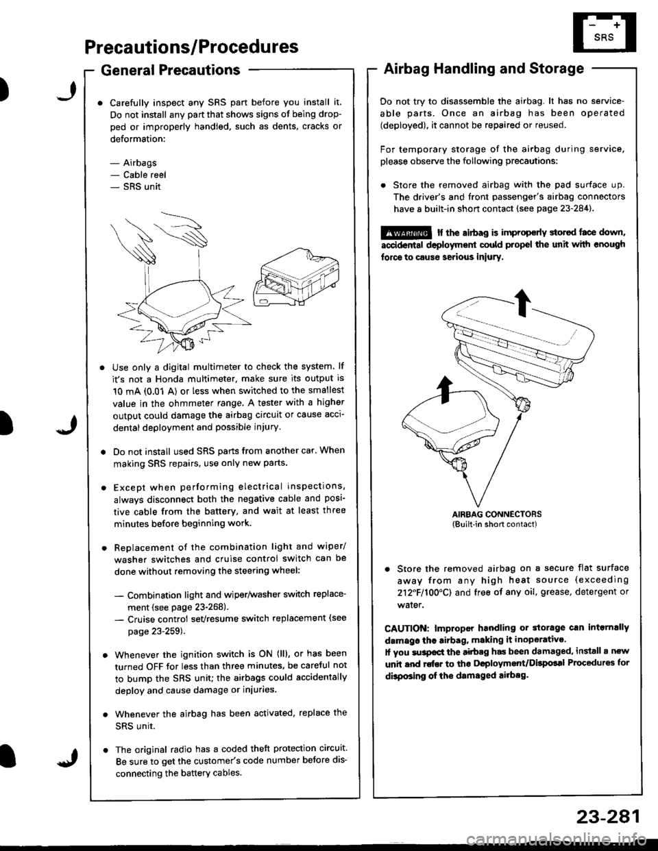
)
Precautions/Procedures
General Precautions
Carefully inspect any SRS part before you install it,
Do not install any part that shows signs of being drop-
ped or improperly handled. such as dents, cracks or
deformstion:
- Airbags- Cable reel- SRS unit
' Use only a digital multimeter to check the system lf
it's not a Honda multimeter. make sure its output is
10 mA (0.01 A) or less when switched to the smallest
value in the ohmmeter range. A tester with a higher
output could damage the airbag circuit or cause acci-
dental deployment and possible injury.
r Do not install used SRS parts from anothercar.When
making SRS repairs, use only new parts.
r Except when performing electrical inspections,
always disconnect both the negative cable and posl-
tive cable from the batterY, and wait at least three
minutes before beginning work.
r Replacement of the combination light and wiper/
washer switches and cruise control switch can be
done without removing the steering wheel:
- Combination light and wiperlwasher switch replace-
ment (see page 23-268).- Cruise controi sevresume switch replacement (see
page 23-259t�.
. Whenever the ignition switch is ON (ll), or has been
turned OFF for less than three minutes, be caretul not
to bump the SRS unit; the airbags could accidentally
deploy and cause damage or iniuries.
. Whenever the airbag has been activated, replace the
SRS unit.
. The original radio has a coded theft protection circuit.
Be sure to get the customer's code number beJore dis-
connecting the battery cables.
23-281
Airbag Handling and Storage
Do not try to disassemble the airbag. lt has no service-
able parts. Once an airbag has been operated
(deployed), it cannot be repaired or reused.
For temporary storage of the airbag during service,
please observe the following precautions:
. Store the removed airbag with the pad surface up.
The driver's and tront passenger's airbag connectors
have 8 built-in short contact (see page 23-284).
@ r the airbag is improp€rly storcd face down,
accidental deployment could propel the unit with enough
force to caus6 serious iniury.
AIRBAG CONNECTORS(Built-in short contact)
. Store the removed airbag on a secure flat surface
away from any high heat source (exceeding
212F110O'CI and free of any oil, grease, detergent or
water.
CAUTION: lmproper handling or storage can intornally
damags the airbag, making it inoperative.
1l you su3pocl the aitbag has been damaged, install a ncw
unit and rofEr to ths Deployment/Dilpolal Procedures for
dbposing of ihe damsged ailbag.
)