Page 675 of 1681

Steering Wheel
lnstallation
Airbag installation
CAUTION:
. Before installing ths st€€ring wheel, align th€ front
wheels straight ahead.
. Be sure to ingtall the harnoss wirss 90 that they 8re
not pinched or intorfering with other car parts.
. Do not replace the original st€ering wheel with rny
other d8ign, since it will mako h impossiblo to p.op-
erly install the sirbag. {Only use genuinc HONDA
rephcamont parts)
. After rea$embly, contirm that ih€ wheels are still
st.ight 8head and that stooring wheel spoke angle
is correct. It minor spoko aogle sdiustment is n€cas-
sary. do so only by adiustment ol the tis-rods, not by
removing and reposhioning the 3teering who€|.
!@ confirm thst the airbag a33embly is
sscurely attached to th€ steering wheel; otherwi3e,
severe personal iniury could result during airbag
deploymenl.
1. Before instslling the steering wheel. center the
cable reel. Do this by first rotating the cable reel
clockwise until it stoos. Then rotate it counterclock-
wise (approximately two turns) until. The arrow
make on the cable reel label points straight up.
ARROW MARK
| 17-26
\
2. Installthe steering wheel.
NOTE: Be sure the steering wheel shatt engages
the cable reel and canceling sleeve.
CAUTION: Do not tap on ths stearing whool or
stsering column shaft whon in3tslling tha 3teoring
whs6l.
49 N'm ls.o kgf.m. 36 lbf'ftl
Aftach the cruise control sevresume switches con-
nector to the steering wheel clip.
Connect the horn conneclor,
CRUISE CONTROLSET,/RESUME SW]TCHESCONNECTOR
Page 677 of 1681

Steering Golumn
Removal
I
a All SRS wire harnesses are covered with yellow insu-
lation. Before vou disconnect any pan of an SRS wire
harness, disconnect the airbag Gonnectors.
a Whenever the ignition switch is ON (lll, or has been
turned OFF for less than three minutes, be carelul not
to bump the SRS unit; the airbags could accidentally
deploy and cause damage or iniuries.
a For additional precautions, lelel to the SRS sub-section
in section 23.
1. Remove the airbag assembly and steering wheel
(see page 17-25).
2. Remove the lower cover.
3. Remove the driver's knee bolster,
Remove the column covers by removing the
screws.
'//
,,1G
LOWER COVER
17 -28
1.
9.
Remove the SRS wire harness connector from the
connector holder.
Disconnect the cable reel connector and SRS main
wire harness connector (see page 17-24).
CONNECTOR HOI-DER
SRS WIRE HARNESS CONNECTOR
Disconnect the cruse control switch connector from
the cable reel, and remove the cable reel trom the
combination switch.
Remove the turn signal canceling sleeve.
Remove the combination switch from the steering
column by disconnecting the connectors.
Page 682 of 1681
9.
1.
8.
11.
10.
Connect the ignition switch wire connectors to the
under-dash fuse/relay box.
Install the combination switch and connect the con,
nectors. Be sure the wires are not caught or pinched
by any parts when installing the combination switch.
Carefully install the wire harness with the harness
bands and clamps.
Install the spring and turn signal canceling sleeve
onto the combination switch.
Install the cable reel, and connect the cruise control
switch connector.
Connect the cable reel connector and SRS main
wire harness connector (see page '17-27).
NOTE: Align the slot in the cable reel with the pro-jection on the canceling sleeve.
CABLE REEL
CONNECTOR HOLDER
COMBINATION SWITCH
SLEEVE
SRS WIRE
17-33
12. Installthe column covers.
UPPER COLUMN COVER
LOWER COLUMNCOVERscREws
13.
14.
Install the driver's knee bolster.
lnstall the lower cover.
Install the steering wheel (see page 17 26).
LOWEF COVER
Page 684 of 1681

Power Steering Pump
Replacement
NOTE: Before disconnecting the hoses from the pump,
place a suitable container under the vehicle.
1. Remove the belt by loosening the pump adjusting
bolt, mounting bolts and nuts.
2. Cover the Ay'C compressor with several shop towels
to protect it from spilled power steering fluid,
11 N.m11.1 kgf.m, 8 lbl ft)
PUMPINLET HOSE(Low-pressure)
O.RINGReplace.
ADJUSTTNGBOLT
?UMP MOUt'lTlNG BOLTS2a N.m (2.a kgf.m, 17 lbf.ftl
t
7.
Disconnect the pump inlet hose and the pump out-
let hose (High-pressure) trom the pump, and plug
them.
NOTE: Take care not to spill the fluid on the body
or parts. Wipe off any spilled fluid at once.
Remove the pump mounting bolts, then remove thepump.
NOTE:
. Do not turn the steering wheel with the pump
removed,
. Cover the opening of the pump with a piece oftape to prevent foreign materiai from entering
the oumo.
Connect the pump inlet hose and the pump outlet
hose (High-pressure). Tighten the pump fittings
securelv,
Loosely install the pump in the pump bracket with
the mounting bolts, nuts and adjusting bolt.
Installthe DumD belt.
CAUTION:
. Mako suro that the power staering belt is prop-
erly positioned on the pulleys.
a Do not gst powor 9t99ring fluid or greas€ on thepower steering bclt or pulley facos. Clesn off any
tluid or grea3a botoro installation
POWER STEERING BEI-T
Adjust the pump belt (see page 17-20).
Fill the reservoir to the upper level line (see page'11.211.
8.
a
17-35
Page 690 of 1681

Power Steering
Gearbox
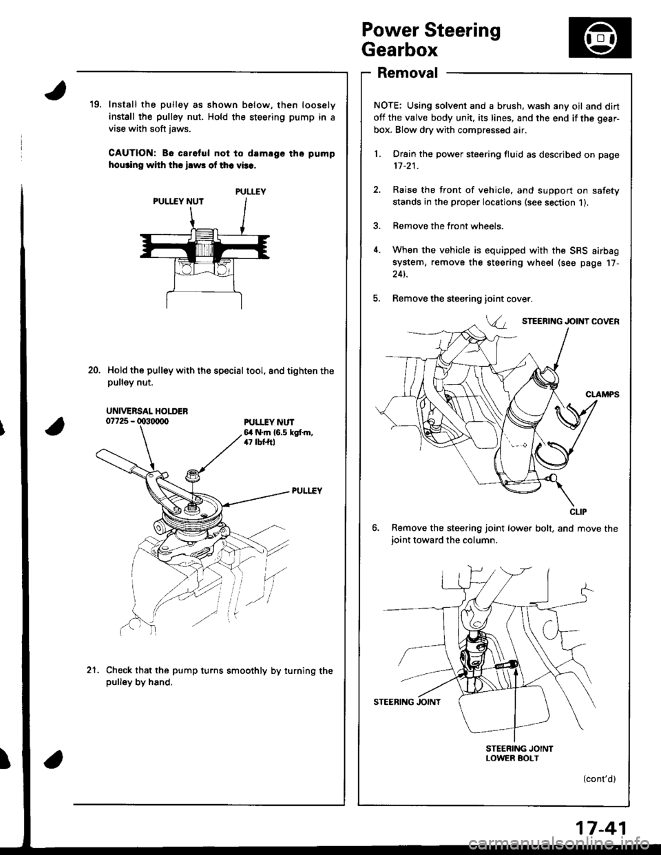
Removal
NOTE: Using solvent and a brush, wash any oil and dirt
off the valve body unit, its lines, and the end if the gear-
box. Blow dry with compressed air.
l. Drain the power steering fluid as described on page
11-21.
2. Raise the front of vehicle, and support on safety
stands in the proper locations (see section 1).
3. Remove the front wheels.
4. When the vehicle is equipped with the SBS airbag
system, remove the steering wheel (see page 17-
24t.
5. Remove the steering
6. Remove the steering joint lower bolt, and move the
ioint toward the column.
STEERING JOINTLOWER SOI-T
(cont'd)
19. Install the pulley as shown below, then loosely
install the pulley nut. Hold the steering pump in a
vise with soft jaws.
CAUTION: Be carelul not to damlge tho pump
hou3ino with ths ilws of th6 vies.
Hold the pulley with the special tool, and tighten thepu ey nut.
ioint
Va
20.
PULI.IY NUT6,1 N.m {6.5 kgt m,47 lbf,ftl
'(
Check that the pump turns smoothly by turning thepulley by hand.
.-l
21.
PULLEY
UNIVERSAL HOLDER
CLIP
17-41
Page 708 of 1681

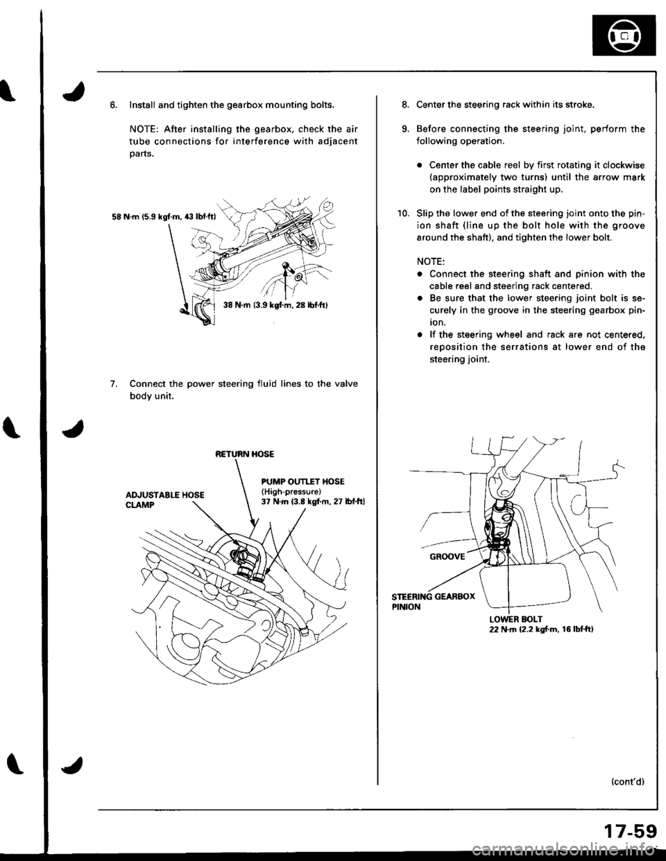
Install and tighten the gearbox mounting bolts.
NOTE: After installing the gearbox, check the air
tube connections for interference with adjacent
parts.
58 N.m 15.9 kgl.m, 43 lbf.ftl
Connect the power steering fluid lines to the valve
body unit.
7.
38 N.m {3.9 kgt m, 28 lbf.ftl
RETURN HOSE
PUMP OUTI.TY HOSE(High-pressure)
37 N.m (3.8 kgf.m, 27 lbt.ftl
Center the steering rack within its stroke.
Before connecting the steering joint, perform the
lollowing operation.
. Center the cable reel by first rotating it clockwise(approximately two turns) until the arrow mark
on the label points straight up,
Slip the lower end of the steering ioint onto the pin-
ion shaft {line up the bolt hole with the groove
around the shaft), and tighten the lower bolt.
NOTE:
. Connect the steering shaft and pinion with the
cable reel and steering rack centered.
. Be sure that the lower steering joint bolt is se-
curely in the groove in the steering gearbox pin-
ion.
o lf the steering wheel and rack are not centered,
reoosition the serrations at lower end of the
steering joint.
(cont'd)
LOWER BOLT22 N.m {2.2 kgf.m, 16 lbf.ft,
17-59
Page 710 of 1681

)
)
16.Reconnect the tie-rod ends to the steering knuckles,
tighten the nut to the specified torque, and install
new cotter Dins.
COT?ER PINReplace.On reassembly, bendthe cotter pin as shown.
lnstall the front wheels.
Fill the system with power steering fluid and bleed
air from the system (see page 17-21).
After installation, perform the tollowing checks.
. Check the gearbox for leaks (see page l7-23).
. Adjust the front toe (see section 18).
. Check the steering wheel spoke angle. Adjust by
turning the right and left tie-rods equally, it nec-
essary.
Ball Joint Boot Replacement
CAUTION: Do not contaminste th! boot in3tllhtion sec-
tion with grca3o.
1. Remove the boot from the tie-rod end, and wiDe the
old grease off the bsll pin.
2. Pack the lower area of the ball pin with fresh grease.
3. Pack the interior of the new boot and liD with Jresh
grease.
CAUTION:
r Keep grease off tho boot inst.llrtion section 8nd
ths tapered 3cction if tho ball pin.
. Do not lllow du3t. dirt. or other foreign matcrials
to entar lh6 boot.
17.
18.
Lfp -A-1
L:I
ru
Install the new boot using the special tool as shown
Derow.
NOTE: The boot must not be a gap at the boot instal-
lation sections.
CAUTION: Aftor installing tho boot, chock tho ball
pin tapgrgd 3oction tor grorsg conttmination, and
wipe it if nccossary.
BALL PIN TAPEREDsEcnoNWipe offthe grease.BOOT INSTALLATIONsEcnoNWipe off the groaso.
19.
FROI{T HUBDIS/ASSEMBLY TOOL07965 - SA5o5o0
17-61
Page 715 of 1681

\
Front Toe Inspection/AdjustmentRear Toe Inspection/Adjustment
NOTE: Use commercially-available computerized four
whesl alignment equipment to measure wheel align-
ment (caster, camber, toe. and turning angle). Follow
the equipment manufacturer's instructions.
1.
2.
Check the tire pressure.
C€nter steering wheel spokes.
Check the toe with the wh€els pointed straight
ahead.
Front to6: 0 i 2 mm (0 t 1/16 in)
- lf adjustment is required. go on to step 4.
- lf no adjustment is required, remove alignment
equrpm€nr,
Loosen the ti€-rod locknuts and turn both tie-rods in
the same direction until the front wheels are in
straight ahead position.
Turn both tie-rods equally until the toe reading on
the turning radius gauge is correct.
After sdjusting, tighten the tie-rod locknuts.
NOT€: Reposition the tie-rod boot if it is twisted or
displaced.
TIE-ROD LOCKNUT14 x 1.5 mm
6.
a
NOTE: Use commercially-available computerized four
wheel alignment equipment to measure wheel align-
ment (caster, camber, toe, and turning angle), Follow
the equiDment manufacturer's instructions.
1. Release parking brake.
NOTE:
. Measure difference in toe measurements with
the wheels pointed straight ahead.
. lf the parking brake is engaged. you may get an
incorrect reading.
Rear toe-in: 2 11 mm l1l16 i 1/15 in)
- lf adjustment is required, go to step 2.
- lf no adjustment is required, remove alignment
equipment.
Before adjustment, note the locations of adjusting
bolts on the right and left compensator arms.
Loosen the adjusting bolts and slide the compen-
sator arm in or out as shown, to adjust the toe.
Tighten the adjusting bolts.
ADJUSTING BOLT10 x 1.25 mm
COMPENSATOR ARM
. Example;
A{ter the rear toe inspection, the wheel is 2 mm(0.08 inl out of the soecification.- Move the arm so the adjusting bolt moves 2 mm(0.08 inl inward from the position recorded betore theadjustment.- The distance the adjusting bolt is moved should be
equal to the amount out-of-specification.
6a N.m 16.5 kgt m, 47 lbt.ft)
a4 N.m la.s kgI.m, 33 lbf.ft)
18-5