1998 HONDA INTEGRA relay
[x] Cancel search: relayPage 328 of 1681

'*
1i
v3
I
l
i
I
1.
Testing
!@ Do not smoke during tho t€st. Keep open
flame away from your work area.
lf you suspect a problem with the fuel pump, check that
the fuel pump actually runs; when it is ON, you will hear
some noise it you hold your ear to the fuel fill pon with
the fuel fill cap removed. The fuel pump should run for
two seconds, when ignition switch is first turned on. lf
the fuel pump does not make noise, check as followsl
Remove the rear seat (see section 20).
Remove the access panel.
Disconnect the 2P connector from the tuel pump.
CAUTION: Be sure to turn the ignition switch OFF
before disconnecting the wires,
Connect the PGM-Fl main relay 7P connector termi-
nals No. 4 and No. 5 with a jumper wire.
PGM-FI MAIN RELAY CONNECTOR {C,14:}l
2.
3.
4.
5.
FUEL PUMP
{YEL/GRNI
IGN, 1
IYEL/GRN)
JUMPER WIRE
Wire side of female terminals
Check that battery voltage is available between the
fuel unit sub-harness connector terminal No. 2 and
body ground when the ignition switch is turned ON(
).
Wire side of female terminals
lf battery voltage is available, check the fuel
pump ground. lf the ground is OK. replace the
fuel pump.
lf there is no voltage, check the wire harness (see
page 11'125).
FUEL PUMPCoNNECTOR 1C510)
L]l
lrl-r
6l FUEL PUMP
\:/ (YEL/GRNI
4.
Replacemont
@ Do not smoke while working on tuel sys-
tem, Keep open flames away trom your work area.
'1. Remove the rear seat (see section 20) (Hatchbackl
Remove the spare tire lid and the protective cover),
2. Remove the access panel.
3. Disconnect the 2P connector trom the fuel oumD.
Remove the fuel pump mounting nuts.
Remove the fuel pump from the fueltank.
install parts in the reverse order of removal.
ACCESSPANEL
5.9 N.m(0.6 kgl.m,4.3 tbtft)
5.
Replace.
Page 329 of 1681

1L
i
!i
!
{
Fuel Supply System
PGM-Fl Main Relay
Description
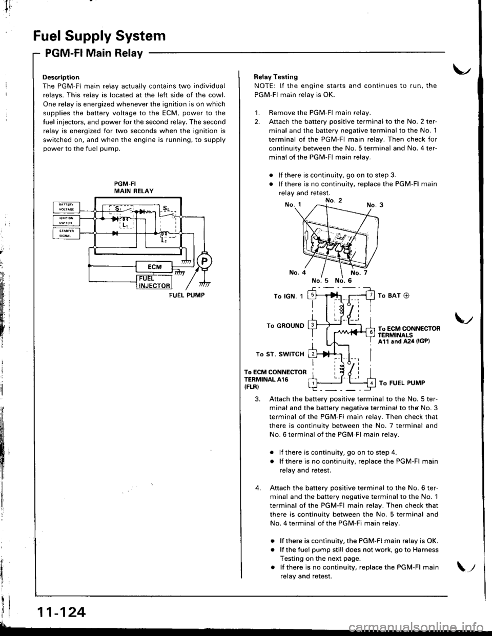
The PGM Fl main relav actuallv contains two individual
relavs. This relav is located at the left side of the cowl.
One relay is energized whenever the ignition is on which
supplies the battery voltage to the ECM, power to the
tuel injectors, and power tor the second relay. The second
relay is energized for two seconds when the ignition is
switched on, and when the engine is running, to supply
power to the fuel pump.
PGM-FIMAIN RELAY
11-124
FUEI- PUMP
Relay Testing
NOTE: lf the engine starts and continues to run, the
PGM-Fl main relay is OK.
1. Remove the PGlvl Fl main relay.
2. Attach the battery positive terminal to the No. 2 ter-
minal and the battery negative terminal to the No. 1
terminal of the PGM-Fl main relay. Then check for
continuity between the No. 5 terminal and No. 4 ter-
minal of the PGN4-Fl main relay.
. lf there is continuity, go on to step 3.
. lf there is no continuity, replace the PGM-Fl main
relay and retest.
To lGN. 1
To GROUND
To ST. SWITCH
To ECM CONNECTORTERMINAL A16
{FLRI
To BAT @
To ECM CONNECTORftNMNALSAll and A24 (lGP)
V
To FUEL PUMP
3. Attach the battery positive terminal to the No. 5 ter-
minal and the battery negative terminal to the No. 3
terminal of the PGM-Fl main relay. Then check that
there is continuity between the No. 7 terminal and
No. 6 terminal of the PGM-Fl main relav.
. lf there is continuity, goon tostep4.
. lf thereis nocontinuity, replacethe PGM-Fl main
relay and retest.
4. Attach the batterv oositive terminal to the No. 6 ter-
minal and the battery negative terminal to the No. 1
terminal ol the PGM-Fl main relay. Then check that
there is continuity between the No. 5 terminal and
No. 4 terminal of the PGM-Fi main relav.
. lf there is continuity, the PGM-FI main relay is OK.
. lf the fuei pumpstill does not work, goto Harness
Testing on the next page.
. lf thereis nocontinuity, replacethe PGM-Fl main
relav and retest.\;
Page 330 of 1681

I
tr,
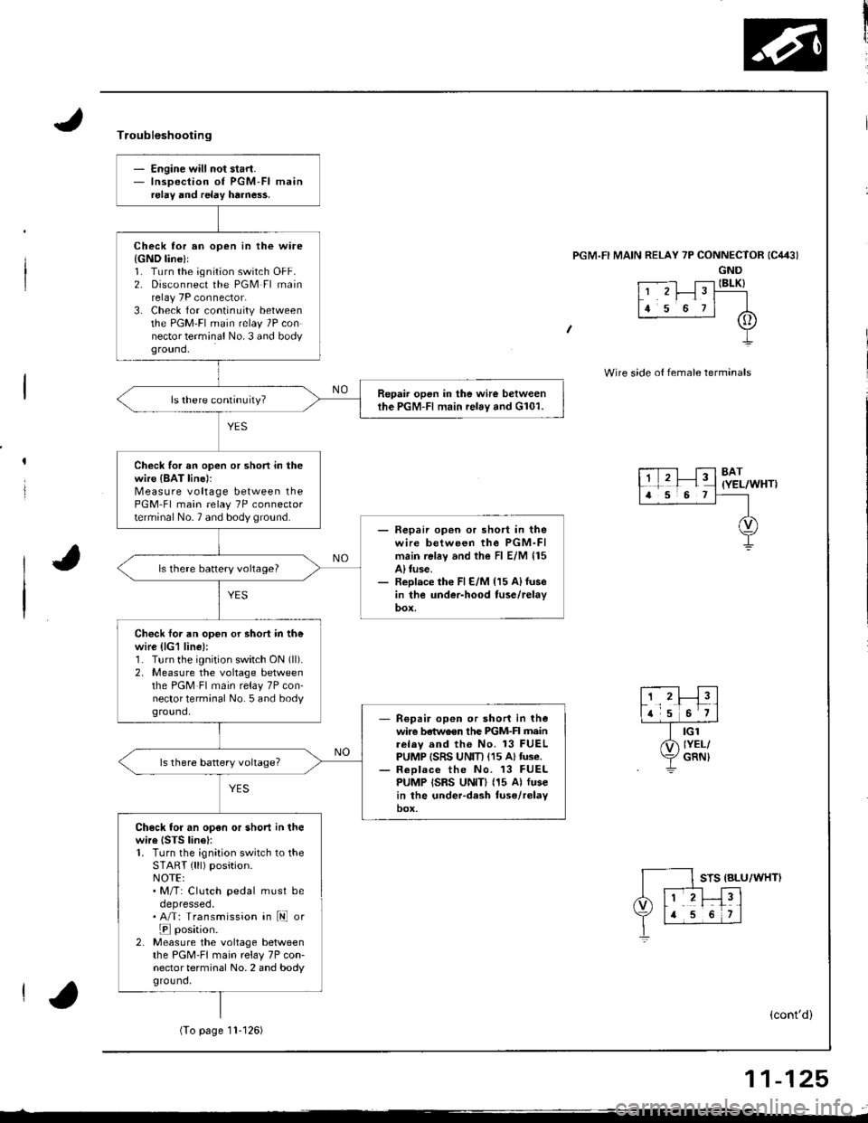
- Engine will not start.- Inspection of PGM-FI mainrelay and relay harne$.
Check lor an open in the ware{GND line}l1. Turn the ignition switch OFF.2. Disconnect the PGM Fl mainrelay 7P connector.3. Check for continuity betweenthe PGM'FI main relay 7P connector terminal No. 3 and bodyground,
Repair open in the wire betweenthe PGM-Fl main relay and G101.
Check for an open or shon in thewire {BAT line)rMeasure voltage between thePGM-Fl main relay 7P connectorterminal No.7 and body ground.- Fepaii open or short in thewire between the PGM-FImain rel6y and the Fl E/M 115A) tuse.- Replace th€ Fl E/M {15 A)fusein the under-hood tuse/relay
ls there battery vohage?
Check foi an open or shori in thewire (lG1 line):1. Turn the ignition switch ON (ll).
2, Measure the voltage betweenthe PGM Fl main relay 7P con-nector terminal No. 5 and bodyground,R€pair open or short in thewire betwo€n the PIGM-FI mainrelav and the No. 13 FUELPUMP ISRS UNIT) (15 Altuse.ReDlace the No. 13 FUELPUMP ISRS UNID (15 Al fusein the under-dash tuse/relayoox,
Check for an open or short in thewire {STS linel:1. Turn the ignition switch to theSTART { lll) position.NOTE:. M/T: Clutch pedal must beoepresseo.. A/T: Transmission in ld or
E position.2. Measure the voltage betweenthe PGM-FI main relay 7P con-nector terminal No. 2 and bodyground,
Troubleshooting
'l RELAY 7P CONNECTOR
GND
t .--.-l T;-l IBLK)L' 'r I" T----
lr s o rl A
+
Wire side o{ female termanals
8AT(YEL/WHT)
STS {BLU/WHTI
(cont'd)
(To page11- t 26)
11-125
Page 331 of 1681

F
I
Fuel Supply
PGM-Fl Main
System
Relay (cont'd)
\
lb
i
(From page 11 125)
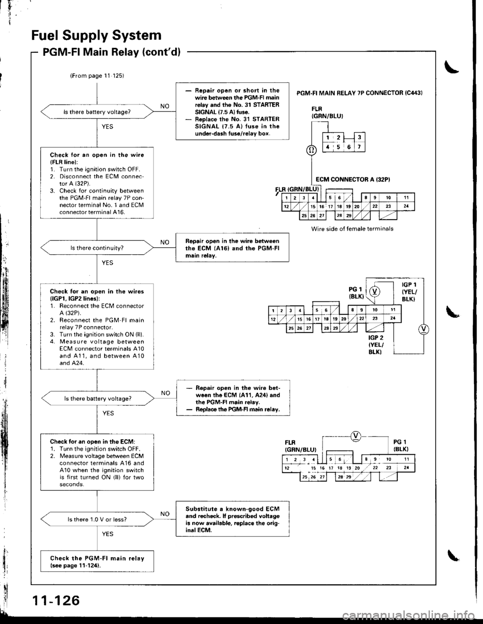
- Reprir open or short in thewire between the PGM-FI mainrelay and the No. 31 STARTERSIGNAL {7.5 A} tuse.- RoDlace the No. 31 STARTERSIGNAL {7.5 A) fuse in theunder-dash luse/relav box,
Check for an open in the wire
{FLR line}:1. Turn the ignation switch OFF.2. Disconnect the ECM connector A (32P).
3. Check for continuity betweenthe PGM-FI main relay 7P con-nector terminal No. 1 and ECMconnector terminal A16-
Repair open in the wire betweenthe ECM (A161 and the PGM-FImein relay,ls there continuity?
Check for an open in the wires{lGPl, lGP2lines}:1. Reconnect the ECM connectorA (32P).
2. Reconnect the PGM-Fl mainrelay 7P connector.3. Turn the ignition switch ON {ll).4. Measure vo ltage betweenECM connector terminals A10and A11, and between A10and 424.
- Repaar open in lhe wir€ bet-ween the ECM 1A11, A24l andthe PGM-FI main relay.- Repldce the PGM-FI main relay.
ls there battery voltage?
Substitute a known-good ECMand recheck. It prescribed vohageis now available. roplace lhe o.ig-inalECM.
ls there 1.0 V or less?
Check the PGM-Fl main relaylsee page 11-124).
PGM.FI MAIN BELAY 7P CONNECTOR IC443I
FLR
FLR
Wire side of temale terminals
Check tor en open in the ECM:1. Turn the ignition switch OFF.2. Measure voltage betlveen ECMconnector termanals A16 andA10 when the ignition switchis first turned ON (ll) for two
IGRN/BLU}
o
1,2!t5i6
:cM CONNEi)TOR A I32P)
I23sl6a9to11
1215lor 17 18t920/22232a
25262l12329
PGl(8LKI
IGP 1
{YEL/BLK}
(
t356I
t5161t la192022
25a
IGP 2{YEL/BLKI
12 15 15 17 18 19 20 .r 22 23
Page 346 of 1681

Evaporative Emission (EVAP) Controls
,J
a
DescriDtion
The evaporative emission controls are designed to minimize the amount of luel vapor escaping to the atmosphere. Thesystem consists of the following components:
A. EvaporativeEmission lEVAPlControlCanister
An EVAP control canister is used for the temporary storage of fuel vapor until the fuel vapor can be purged from theEVAP control canister into the engine and burned.
B. Vapol Purge Control System
EVAP control canister purging is accomplished by drawing fresh air through the EVAP control canister and into a pon
on the intake manifold. The purging vacuum is controlled by the EVAP purge control solenoid valve.
C. Fuel Tank Vapor Control System
When fuel vapor pressure in the fuel tank is higher than the set value of the EVAP two way valve, the varve opens anoregulates the flow of fuel vapor to the EVAP control canister.
FrcmNo. 15FUELTANKPRESSURESENSOR
EVAPTHREE WAYVALVE
EVAP CONTROLCANISTENVENT SHUT VALVE
YEL/- BLK
EVAPBYPASSSOLENOIDVALVE
LT GRN
RED/EVAPTWO WAYVALVE
FUEL TANKEVAP VALVE
FUEL TANK
EVAP PURGE CONTROL SOLENOID VALVE DUTY CON-
TROLLED AFTER STARTING ENGINE
?!l ---- 311'AiS-*(7.s Al
FromPGM.FIMAIN RELAY
VARIOUSSENSORS
----<
YEL
EVAP PURGECONTROLSOLENOID VALVE
(cont'd)
-141
Page 466 of 1681

Terminal NumberSignalDescriptionMaasuring Conditlons/Tarminal Voliage
424ACCLAir conditioning (Ay'C) clutch relay
control
With A,/C comDressor ON: 0 V
With Ay'C compressor OFF: Battery voltage
A25tG1Power supply systemWith ignition switch ON (ll)r 12 V
426LG1Ground
B1Not used
82BAROS SBarometric pressure sensor signal
input
With ignition switch ON (ll) and depending on
barometric pressure: Approx. 3 V
B3ECTEngine coolant temperature sen-
sor signal input
With ignition switch ON (ll) and depending on
engine coolant tem perature: Approx. 0.1 - 4.8 V
B4TPSThrottle position sensor signal
input
With ignition switch ON (ll) 8nd throttle fully
open: 4.14 - 4.82 V
With ignition switch ON (ll) and throttle fully
closed: 0.44 - 0.56 V
B5VSSVehicle speed sensor signal inputWith ignition switch ON (ll) and front wheels
rotating; Pulsing signal
B6AFSBUpshifvdownshift comparative
signal output
With engine idling: 0 V
At uDshift or downshift: 5 V for an instant
B7AFSAUpshifvdownshift com parative
srgnal output
With engine idling: 0 V
At upshift or downshift: 5 V for an instant
B8NCSGCountershaft speed sensor signal
ground
Always: 0 V
B9NCCountershaft speed sensor signal
Input
Depending on vehicle speed: Pulsing signal
When vehicle is stopped:0 V
B10NMMainshaft speed sensor signal
input
Depending on vehicle speed: Pulsing signal
When vehicle is stoDoed: 0 V
811Not used
812STOP SWBrake switch signal inputWith ignition switch ON {ll) and b.ake pedal
depressed: Battery voltage
With ignition switch ON (lll and brake pedal
released:0 V
813Not used
814scsTiming adjustment
service check signal
With ignition switch ON (ll) and service check
connector oDen:5 V
With ignition switch ON (ll) and service check
connector connected with special tool: 0 V
815Not used
816Not used
817NMSGMainshaft speed sensor signalgroundAlways: 0 V
818Not used
819FASShift acknowledge inputWith engine idling: 5 V
At upshift or downshift: 0 V for an instant
820VBEF+5 V referenceWith ignition switch ON {lll: Approx. 5 V
82'lNot used
Not used
14-49
Page 467 of 1681
![HONDA INTEGRA 1998 4.G Workshop Manual Troubleshooting Procedures
Checking the Diagnostic Trouble Code (DTC)
with an OBD ll Scan Tool or th€ Honda PGM Tester
When the TCM senses an abnormality in the input or output systems, the lD,] ind HONDA INTEGRA 1998 4.G Workshop Manual Troubleshooting Procedures
Checking the Diagnostic Trouble Code (DTC)
with an OBD ll Scan Tool or th€ Honda PGM Tester
When the TCM senses an abnormality in the input or output systems, the lD,] ind](/manual-img/13/6069/w960_6069-466.png)
Troubleshooting Procedures
Checking the Diagnostic Trouble Code (DTC)
with an OBD ll Scan Tool or th€ Honda PGM Tester
When the TCM senses an abnormality in the input or output systems, the lD,] indicator light in the gauge assembly will
blink. When the 16p Data Link Connector (DLC) (located under the dash on the passenger side) is connected to the OBD ll
Scan Tool or Honda PGM Taster as shown, the scan tool or tester will indicate the Diagnostic Trouble Code (DTC) when
the ignition switch is turned ON {ll}.
When the !r indicator light has been reported on, connect the OBD ll Scan Tool confirming to SAE J1978 or Honda PGM
Tester to the DLC (16P) behind the ashtray. Turn the ignition switch ON (ll) and observe the DTC on the screen ofthe OBD
ll Scan Tool or Honda PGM Tester. After determining the DTC, refer to the electrical system Symptom-to-Component
Chart on pages 14-54 and 14-55.
NOTE: SeetheOBDll ScanTool orHonda PGM Tester user's manual for specific instructions.
OBD-IlSCAN TOOL orHONDA PGM TESTER
Some PGM-Fl problems will also make the lol indicator light come on. After repairing the PGM-Fl system. disconnect the
BACK Up fuse (7.5 A) in the under-hood fuse/relay box for more than 10 seconds to reset the TCM memory, then recheck.
NOTE: Disconnecting the BACK UP fuse also cancels the radio anti-theft code, preset stations and the clock setting. Get
the customer's code number, and make note of the radio presets before removing the fuse so you can reset them
uJ trr
ulu
ai
14-50L
DATA LINK CONNECTOR (16P)
I
il
lt
rJq
Page 468 of 1681

L./Checking th€ Diagnostic Trouble Codo (DTC)
with the Sowica Check Connector and Special Tool
When the TCM senses an abnormality in the input or output systems, the [D;l indicator light in the gauge assembly willblink.
When the Service Check Connector (located under the dash on the passenger side) is connected with the special tool asshown, the E1T indicator light will indicate (blink) the Diagnostic Troubte Code (DTC) when the ignition switch is turned ON{
}.
When the @ indicator light has been reported on, connect the Service Check Connector with the special toot.
GAUGE ASSEMEI.Y
Then turn ON (ll) the ignition switch and observe the E indicator light.Codes 1 through 9 are indicated by individual short blinks. Codes 1O and above are indicated by a series of long and shortblinks. One long blink equals 10 short blinks. Add the long and short blinks together to determine the code. After deter-mining the code, refer to the electrical system Symptom-to-Component Chart on pages 14-S4 and 55.
\-F;ii^r
) ,J
Se. OTCI
Soo DTC2
Long blinkShort blinb lfive timcsl
Soe DTCl5
Some PGM-FI problems will also make the E indicator light come on. After repairing the PGM-FI system, dasconnect theBACK UP fuse No. 47 (7.5 A) in the under-hood tuse/relay box for more than 1O seconds to reset the TCM memory, thenrecnecK.
NOTE; Disconnecting the BACK UP fuse also cancels the radio anti-theft code, preset stations and the clock setting(cont,d)
Short blink loncsl
\-/ \i,
14-51