Page 1296 of 1681

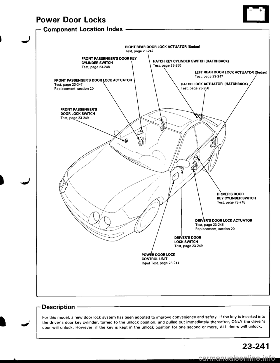
Power Door Locks
Component LocationIndex
RIGHT REAR DOOR LOCK ACTUATOR {SedanlTest, page 23-247
FRONT PASSENGER'S DOOR KEYCYI-INDER SWITCHTest, page 23-248
HATCH KEY CYLINDER SWITCH (HATCHBACK)
Test, page 23-250
LEFT REAR DOOR LOCK ACIUATOR (Scdlnl
Test, page 23'247FRONT PASSENGER'S DOOR LOCK ACTUATORlest, page 23-247Replacement, soction 20HATCH L(rcK ACTUATOR IHATCHBAC(ITest, page 23-250
FRONT PASSENGER'SDOOR LOCK SWITCHTest, page 23-249
DRIVER'S DOORKEY CYLINDER SW]TCHTest, page 23-248
OOOR LOCK ACTUATORTest, page 23-246Replacement, section 20
DRIVEB'S DOORLOCK SWITCHTest, page 23-249
oooR LocKCONTNOL UNITInput Test, page 23-244
-)
J)
I
For this model, a new door lock svstem has been adooted to imDrove convenience and salety. lf the key is inserted into
the driver's door kev cvlinder. turned to the unlock position, and pulled out immediately thereafter, ONLY the driver's
door will unlock. However, il the key is kept in the unlock position for one second or more, ALL doors will unlock.J
23-241
Page 1297 of 1681
Power Door Locks
Circuit Diagram
@*"
DR]VER'S000R LocKSWITCH
NATCN KEYCYLINDER SWITCH
L_____
ooon rocx xroe If7 l
VIKEY
DRIVER'SDOOR LOCKACTUATOR
E
UNDER.HOOO FUSEi RELAY BOX
N0.41 (1004) No.s4 (40A)
DFIVERS DOORKEY CYLJNOERSWITCH
WHT/GRN
FRONTPASSENGERSDOOR LOCKACTUATOR
T--=-l-4{il^
* LEFT REARDOOR LOCKACTUATOR
,@-
* RIGHT NEARDOOR LOCKACTUATOH
-4{.ill^
HATCH LOCKACTUATOR
T-:-lfl.|.{-
LTGRN
LT BLU
A
t--lt=JKEY
i
Atl
T-tl-lKEYBLK
I
G503
.LK BLKll
tlAA
:-l
G501 G2r.G502 ercl
BLK
,l'
G5o1G502
LOCK
o
POWER DOORLOCK CONTROLUNIT
8LK
A-l
G501G502
23-242
Page 1298 of 1681

I,t
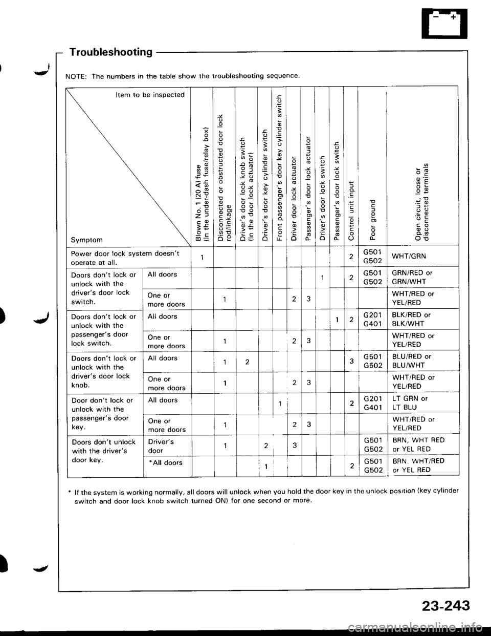
Troubleshooting
* lf the system is working normally, all doors will unlock when you hold the door key in the unlock oosrtion {key cylinder
switch and door lock knob switch turned ON) for one second or more
)
NOTE: The numbers in the table show the troubleshooting sequence
Item to be inspected
Symptom
g
z:t
;i
:
5
{,!
(,o
o-c
E5
B
'io
B
o)c
c
o
:
D
.uo
I
o)
o-
-c
:o
o
I
!
o)
cJ
o
c
c
o)
Power door lock system doesn't
operate at all.
G501
G502WHT/GRN
Doors don't lock or
unlock with the
driver's door lock
switch.
All doors2G 501
G502
GRN/RED or
GRN/WHT
One or
more doors
'I23WHT/RED or
YEL/RED
Doors don't lock or
unlock with the
passenger's door
lock switch.
All doors1G201
G401
BLK/RED or
BLK/WHT
One or
more ooors123WHT/RED or
YEL/RED
Doors don't lock or
unlock with the
driver's door lock
knob.
All doors123G501
G502
BLU/RED or
BLU/WHT
One or
more doors123WHT/RED or
YEL/RED
Door don't lock or
unlock with the
passenger's door
key.
All doorsl2G201
G401
LT GRN or
LT BLU
One or
more doors2WHT/RED or
YEL/RED
Doors don't unlock
with the driver's
door key.
Driver's
ooor23G501
G502
BRN, WHT REO
or YEL RED
*All doors1G 501
G502
BRN, WHT/RED
or YEL RED
-
23-243
Page 1300 of 1681

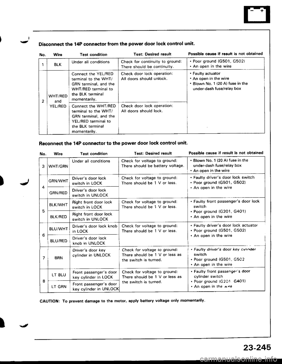
Disconnect the 14P connector from the power door lock control unit'
)
No. WileTest conditionTest: Dgsired resultPossible causo if rosult is not obtained
Reconnect the 14P conneetor to the power door lock control unit'
No. wireTest conditionTest: Desired resultPossible cause il result is not obtained
I
1BLKUnder all conditionsCheck tor continuity to ground:
There should be continuity.
. Poor ground (G50'1, G502). An open in the wire
2
WHTi RED
ano
YEL/RED
connect the YEL/RED
terminal to the WHT/
GBN terminal, and the
WHT/RED terminal to
the BLK terminal
momentarily.
Check door lock operation:
All doors should unlock.
Faulty actuator
An open in the wire
Blown No. 1 {20 A} fuse in the
under-dash Juse/relay box
Connect the WHT/RED
terminal to the WHT/
GRN terminal, and the
YEL/RED terminal to
the BLK terminal
momentanly.
Check door lock operation:
All doors should lock.
3WHT/GRN
Under all conditionsCheck for voltage to ground:
There should be battery voltage.
. Blown No. 1 (20 A) fuse in the
under-dash fuse/relay box. An open in the wire
GRN/WHTDriver's door lock
switch in LOCK
Check lor voltage to ground:
There should be 1 V or less.
Faulty driver's door lock switch
Poor ground (G501, G502)
An open in the wire
GRN/REDDriver's door lock
switch in UNLOCK
5
BLK/WHTRight front door lock
switch in LOCK
Check for voltage to ground:
There should be 1 V or less.
Faulty front passenger's door lock
switch
Poor ground (G201 , G401)
An open in the wireBLKi REDRight front door lock
switch in UNLOCK
BLU/WHTDriver's door lock knob
in LOCK
Check for voltage to ground:
There should be 1 V or less.
. Faulty driver's door lock actuator. Poor ground (G501, G502). An open in the wire
BLU/REDDriver's door lock
knob in UNLOCK
7BRN
Oriver's doo. key
cylinder in UNLOCK
Check for voltage to ground:
There should be 1 V or less as
the switch is turned.
. Faulty driver's door key cvtrrder
switch. Poor ground (G501, G502. An open in the wire
8
LT BLUFront passenger's door
key cylinder in LOCK
Check for voltage to ground:
There should be 1 V or less as
the switch is turned.
. Faulty front passengef's door
cylinder switch. poor ground lG20r G4Ol). An open in the *reLT GRNFront passenger's door
key cylinder in UNLOCK
\J
CAUTION: To prevent damage to the motol, apply battery voltage only momentarily
23-245
Page 1303 of 1681
Power Door Locks
Driver's Door Key Cylinder
Switch Test
1. Remove the door panel (see section 20).
2. Disconnect the 2P connector f.om the switch.
terminal side
Check tor continuity between the terminals in eachswitch position according to the table.
Front Passenger's Door Key Cylinder
Switch Test
1. Remove the door panel (see section 20).
2. Disconnect the 3P connector from the switch.
FRONTPASSENGER'SDOOR KEYCYLINDERSwlTCH
CONNECTOR
3. Check for continuity between the terminals in eachswitch position according to the table.
Terminal
il;------__\tt
UNLOCKoo
OFF
Terminal
P**--__\c
LOCKo--o
UNLOCKoo
UNTOCK<
I
UNLOCK
r--O\:
I LOCK
23-248
(--l__!J KEYtil
Page 1305 of 1681
Power Door Locks
Hatch Lock Actuator Test
Remove the rear t.im panel (see section 20).
Disconnect the 6P connector from the actuator.
1.1.
2.
Hatch Key Cylinder Switch Test
Remove the rear trim panel (see section 20).
Disconnect the 3P connector from the switch.
3. Check for continuitv between the terminals in each
switch position according to the table.
6P CONNECTOR
3. Check actuator operation by connecting power andground according to the table.
CAUTION: To prev€nt damage to the actuator,
apply battery voltage only momeniarily.
1 lf the actuator fails to work properly, replace it,
23-250
Terminal
ilil;---tBc
LOCKoo
UNLOCKo
Terminal
ilil;-]E
LOCK@o
UNLOCKoo
UNLOCK
.-,4
I LOCK
| !J KEY
Page 1306 of 1681
Hatch Opener
Circuit DiagramHatch Latch Switch Test
Remove the rear trim panel lsee section 20).
Disconnect the 6P connector from the switch.
3. Check for continuity between the terminals in each
switch position according to the table.
HATCHOPENEHRELAY
HATCHOPENERACTUATOB
UNDER-HOODFUSE/RELAYBOX
UNDER.DASHFUSE/RELAYBOX
la :llf q ^ll
ELUMHT YEURED
tl
[S-l*0,., f/tl| IoPENEF lt.l I
I ? l'*n'" +_i
tl8LK BLK
tl
tl
tt.:
G503 G503
BATTEFY
(+)
Y
I
-r--t
I I lm,1
uI| )Nov II f. (4oA) |rT '
IWHT/RED
I-r----| )ur II L (2oA) I
IWHTiGRN
fi--l->t_:___J-KEY
Terminal
:- ..- crosrUon-1UNLOCK
LOCK
F
23-251
-----t1< IKEY--,_)
J
Page 1340 of 1681

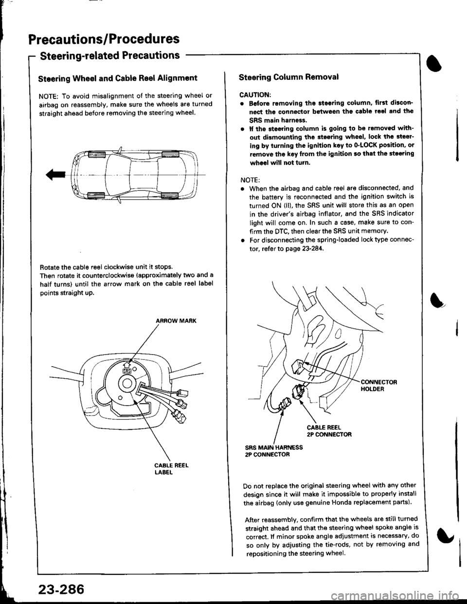
Precautions/Procedures
Steering-related Precautions
Steering Wheel and Gable Reel Alignment
NOTE: To avoid misalignment of the steering wheel or
airbag on reassembly. make sure the wheels are turned
straight ahead before removing the steering wheel.
Rotate the cable reel clockwise unit it stops.
Then rotate it counterclockwise (approximately two and a
half turns) until the arrow mark on the cable reel label
points straight up.
ARROW MARK
23-286
Steering Column Removal
CAUTION:
. Before romoving the steoring column, lirst di3con-
nect ths connector bctwoen tho csble rsal and the
SBS main harneEs.
. lf the steeting column is going to be rsmoved with-
out dismounting the steering wheel, lock the steer-
ing by iurning the ignition k6y to o'LOCK position' or
remove tho key lrom thc ignition ro that the steering
wheel will not turn.
NOTE:
When the airbag and cable reel are disconnected, and
the battery is reconnected and the ignition switch is
turned ON (ll), the SRS unit will store this as an open
in the driver's airbag inflator, and the SRS indicator
light will come on. In such a case, make sure to con-
firm the DTC, then clear the SRS unit memory.
For disconnecting the spring-loaded lock type connec-
tor, refer to page 23-284,
SRS MAIN HARNESS2P CONNECTOR
Do not replace the original steering wheel with any other
design since it will make it impossible to properly install
the airbag {only use genuine Honda replacement parts).
After reassembly. confirm that the wheels are still turned
straight ahead and that the steering wheel spoke angle is
correct, lf minor spoke angle adjustment is necessary, do
so only by adjusting the tie-rods, not by removing and
repositioning the steering wheel.
L