Page 1527 of 1681
Fog Lights
UNDER-HOODFUSE/RELAYBOXi-f;;-| neroucrt
!__L':___
:;i!'r.
6€e HeadlightSwitch,page 10O.
Y
I
-.1.*.
Flash.to-pasE ISwitch /
orrl-t o"t*
oir.r, {-Swltch \",I-J -
lt:
-- -'t coMBtNATtoN1H€8dT I LIGHT
lggltl"" iP#[9]l
*,JI-
See HeadlightSwitch,page |00.
ON
"oN"
INDICATOR
FOGLIGHTIN-LINEFUSEPHOfO 123
FOGLIGHTREI.AYPHATO 122
See HeadliohtSwitch,page 100.
cl6
RIGHTFOG LIGHT
------Tl'c42
elurneo ll
".u,".of, "t"to% u,
A csroBLU/REO ll PHO|O tr
Ut",'ry*
"'fi
',ua'r.,o
"'
110-14
..- c4o -a-----l c3o1: PHoro 122 : : pHaToll
Page 1528 of 1681
Dash and Console Lights
r-r---1 UNDER-HOODI I FUSE 51 I FUSE/RELAY] +BSMALL :BOXI { 1sA I pHoro2l
L-g---J9 Y C217wxr I euoro zt
s I ccssCOMBINATIONf --*--f Headtio l LIGHT
; xe1 \orr I swncri ii#[.%
I \--?_r I'
I L-]Id=J IL---Y.------J
See Headlight Switch,page 100-1.FUSE 30ttstnoMEt{tuGt{Ts7.54
*,"1'-19'x%*
",0,u.* !l j"-.*- - - -
;:tr-
- - - - - - - -
T-
- - - - - - - ;fi .i']f,- - - - - -,u.*
aE-t I I c---a@,
: [, 3 Jf c566 ll ll ll ll
i
"-",
lii,;-:r
lr;+'+.
[ ",.. r",,u**,i;"':l ",.."**. |
*".
I ",,,
OPTIONCONNECTOR(Oash Lighis)
, ll BRTGHTNESS' 3.a C562 CONTROLLER
Atl., .ffi"gifli irffit1jr''rs*l pi*;l-".
-"
l'ol"*,T*' ilF-Jffi-i[==:--- *.?j'?,u
: l-,LJ Y :L
i=rfr:={-l"'=
.-i"ffi
l"
"." I I
RED
l2-,J
*.' cqor
114
Page 1529 of 1681
UNOER-DASHFUSE/RELAYBOXI
t
I
,
r-1 TNTEGRATEoI I coNTRoL UNIT| | PHOfO 62
J
xa
c440
A &??f,,""'"'u-ror
I PHora 51
il,.,.::r---j
Oerminals-;;i3L*
4 :---
i ! "ro".*l
1'&! ".0"*l ,flsx'"*
, .1, "uu, o I "uuu "eo "'*
!t'-lF'r HAZABD r-lF'r CRUTSE rE==I I IWARNTNG | | lCONrRoLl I
i6i**" i6i***'. i6ii€#16l*"" igi***'. i6!€Hf=ri
iLi iJ.i Ll-'sryi:8
f
cs63 s
f
csss "?L--- j:
"'"1
"* ,ri*,";f ".o
"l
-;-.;FI-
".o I ir-u:r'out I
L----Js:::,--,-"'
FED/BLK
FEO/BLK
SLK
FEO/BLK
CIGABETTELIGHTER
c404
c67?
c684
HEATERCONTROLPANEL
C411 FEO/BLK
12
FED/BLK
I
BBril"l
I
@
r
I
I
I
I
I
I
I@@
u_c684
C677
c404
10FEO
RED
9BED
I
J'
-------J
1 14-1
Page 1530 of 1681
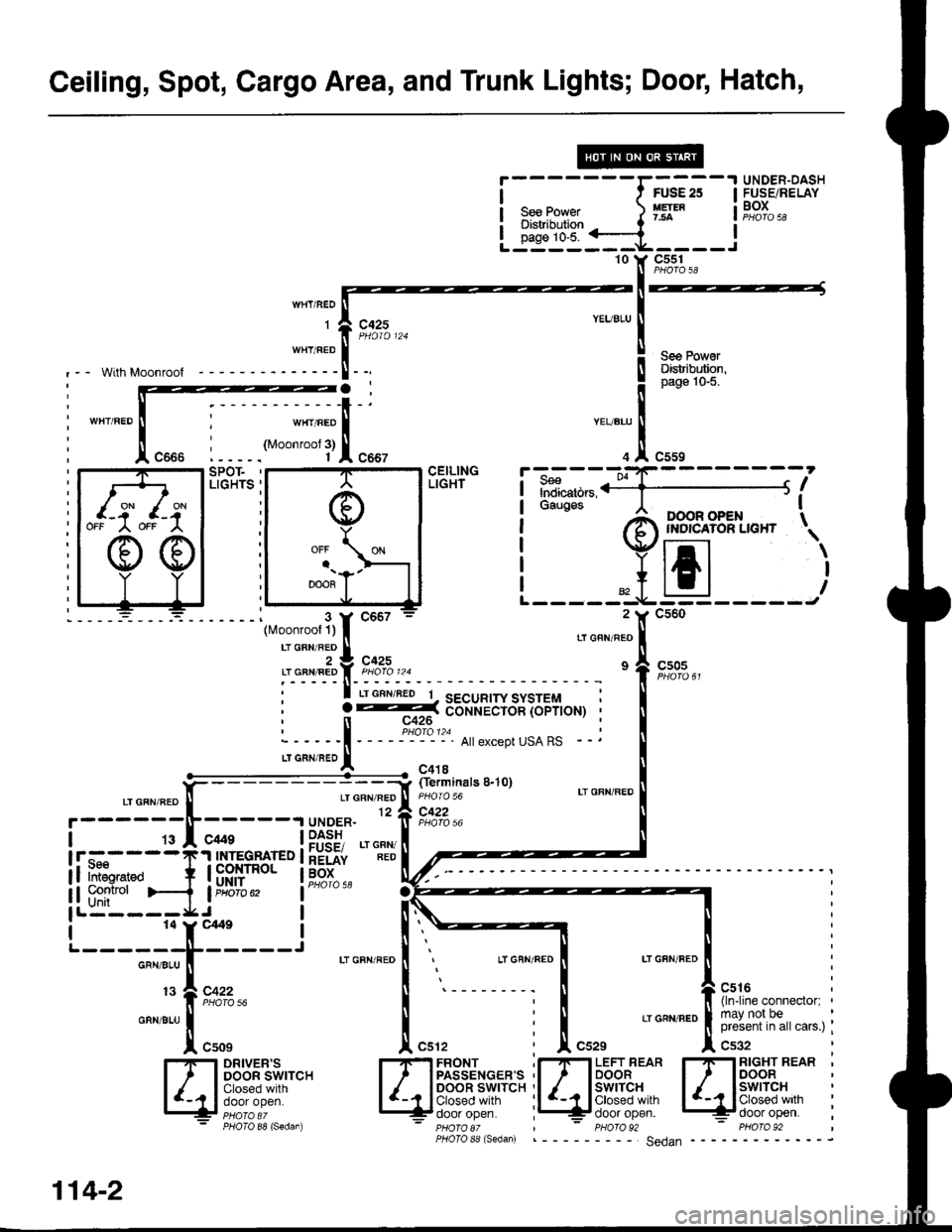
Ceiling, Spot, Cargo Area, and Trunk Lights; Door, Hatch,
i
- - - - - - -rffi
;
-
I H,!8",klf;""
I s""Po*"r. ) Ifl* i!,?t,,: Distribution t '-
!-id"i::=a----l'10 Y C55110 Y C5s11l PHOTO aA
-l--
IYEUBLU
I
i qpq Fv"'ll uElnDuron.! page'lo-5.
"Tl",,,
Indicators,ii1;](;;;' I II'OOR OPEN TINDICAIOR LIGHT \
tJEJ
With Moonroof
c425
wHr/BEoJl
::'::l[
LIGHTS '
-:_ __i (ferminats 8.10)
CEILINGLIGHT
,-, o"n "a9 [ rroro ro LT GFN'REDGFN/REO12 a C422if pForo )6
| _9I _c*s __ |PfSE, .'"""
t!-f."----T'! IU.E9F FD I hEiii iiD
if ifr*"o + l8Rllr"o' ti;91".. l1---
i i i:tr#i">-{ i"usfl. lai6iose
lL:---=*J-.^ |
'---=r,f;---J .'""""."i
.-E
.,o"""."f.u,.
I-I-I DRIVER'S I-IF] FBONT .I-IFI LEFT REAR I-IFI RIGHT REAB 'l, IDooRswrrcH l, IPASSENGEBS,I I loo.|orB" l/ ISSP;B, :
ll+lF.":"::r!!r lglp;?"',"i,:;i'''"" il /-r|il{':!,sf l '-11:$"|I,lr
i
13?,c:::""" I
'--------;
I t{r"rn".iil""onn""to., ,
o"n".u| | : | 'oa',n."|[3r,J#,1?,,"",",;
| "uor ,f[ cu', i J[ cszs ,1, c'g,
PHOIO 88 (Sedan) - pHOrO 8t | - PHOrO 92 - PHO|O 92PHoIo 88 (s6dan) ___ Sedan
a-t c-{OFF
OFF A
";flxl
3::; ;;il;;;
::"T{ ;,
2 Y C560
' ? --=:( d-o-n-r.iiiicin ioprroHr, n c426
:_---_i - _ _ _:Plo_'?. A||exceptusARs _
LTGRN,BE'I - c4'r8
114-2
Page 1532 of 1681
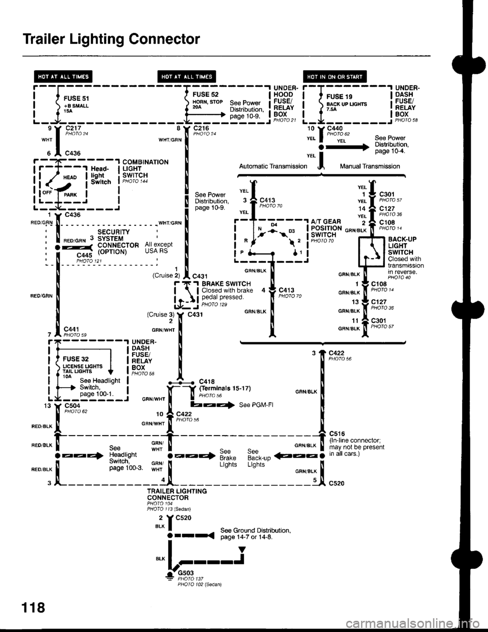
Trailer Lighting Connector
rl;:'
H***
', J "' o, "'oto'o
; -
l-
- - - - - -
iiiJnlw
,i%*,*:l Y* | L-i+--.r tdl##i*
I (c,uise ir I 6a31- ..._ -....__::"
*-
| ."u ", * [ in reverse.
u iti!ms..:y'I'9|| .["...
- -l*s;.,g,."'""
,",0:;"* *";,1 I "*'"tt-fiF'1%"
FUSE32 | i:gPfu [ '89"'::.,"
ili'*'U"T*.,t,., !Fst., J--. .0,.
l[r!g:_l """*",f-l g:lTinars 1s-17)
;04 [ ba{ See PGM-FI)ro 62 fi A cczz
".":.:Xt*" """,,J"',it'*'**=
.EE4 :e?d,,!h,
""' i-:.+ 9t= 9:9___- €::5 ;;;irc;;ai
".o".* | il',iii'1t.. $11 |
Lisnii Lb;i;' o"n,.* |
. JL-----------1JI- ljl c'ro
TRAILER LIGHTINGCONNECTOR
2 Y Cs20BLX I - See Ground Drstnbutron,Orrr{ Oaqe r4-7 or 14-6.T-IY"," I I--'I^-rrr-
r:-910,3,.,,
PHOIO 102 lsedanl
5 A C435 | ver- | IrcsE rv-q
if:T---r J;l l-'!ti^*t" I oromaticrransmission I Manuarrransmission
ll(':'iis,i'"nl;*ri"* i ffi
i l#.1"-"
I sw*ch ' Piu''J 'r
L*'**r*,
"]l
"*. "iU t*.,
L'_-_L-_-_'___..!
".o 0,," l( "o.u I
o"o" to-s
_:l_____ 1,!,| ,";:,'","
"'""i'!;
:isr"H"" ^; j""":"" t []t lil?lfililr
""""ff*:;
Lfl6ti*-" i--g-----J
F T'I BRAKE SWITCH TI
Ilj iiifl'#'!"';l-"' tr
""#"3 "
lf c431 GRN/BIK
I
it
*)ir;***"{:"- [:**"
"":r[;;,,
-",*l"Y ""#B'' J.l1nqi, se€Power
.-3:i!i,Jil
I swllch I PH(,,/ci r44
! ,"" ,o*", "ttl "T
U .rot
8 Y C216
il-l-
118
Page 1548 of 1681
- How the Circuit Works
The immobilizer system is designed to prevent the
car f rom being started without the owner's ignition
key. lf an attempt is made to start the car without
the correct key, the immobilizer system will disable
the car's fuel supply.
The immobilizer system consists of the ignition key,
immobilizer receiver unit, immobilizer indicator
light, PGM-FI main relay, fuel pump, and the PCM
or ECM.
With the ignition switch in ON (ll) or START (lll), the
immobilizer receiver unit and the PCM or ECM
receive an "ignition on" signal through fuse 44 and
the PGM-FI main relay. The PCM or ECM then
sends power to the ignition key transponder through
the immobilizer receiver unit. The transponder then
sends a coded signal back to the PCM or ECM
through the receiver unit. lf the signal is correct, the
PCM or ECM will energize the car's fuel supply
system by grounding the PGM-FI main relay. The
immobilizer indicator light flashes a code to indicate
that the correct key has been inserted. lf the
ignition key signal is not correct, the PCM or ECM
will not energize the car's fuel supply system by not
grounding the PGM-Fl main relay. The immobilizer
indicator light then flashes a code to indicate that an
incorrect key has been inserted.
Refer to the Service Manual (Section 23,
Body Electrical) for specific tests and
troubleshooting procedures.
132-1
Page 1550 of 1681
a
)'-
I
1
i
I
-----'!rex^ER illt#lP$3"'s'J39"
I li33,i i i H^- lPHarc2'
l_.,*_______,fr_j F;t':"' i*.,;-,; lnpu Inpw t iidr'o az 9 l, C2j6' Ptioro )4,.llF-------il(coo+ r
I I
wHr I see tuwer
a.rn;o
I
eL,"v*r
I ii---- 3;*1tB:
.-r--------J^.^. I -l'.
f
------l6-f "',f""3,,
u.^,".o I ".*-", i
TI
,o l--------J "o,,
er-rcneol arx,wxrl I f-------.Jln:SY,,
'o
f
----- -qh9i","
""
i
aix,wxr
!
LIGHTFLASHER
+ (cont'd)
J
;LT-ffi}-hf[
-";][-. -:-[;^.
rz A-_-"1 '1" -1A-----------19
tlar.x.n:o ll ELKwHr ll GRN'YE
I tls A__-- -_--9J.t---- - - --- - - -1!
ll ,ll ","',' ll
' ' -
[*"*:iL_____::lL_
ill
""'"n
!-----:1 sEcuRrrr i!
I unrock output Loc* output fiirn[|. ! Eg,f"o. i\. siren contror ,gil,", ! ildib., I| -;;-q Hood swirch input t : r c44iA------ 7
PHOrO 5e9 t|'- - -^:1t- - - - - - - - ;'lf
!1ft"c*39,,, ij:g+ ffi,U',:.
*.ll ".o,o"n I
pase'ro*l'
]ZJ{ T
-
-:[:-;nT:===;.TIf
-----
ithT#'**l!$gs]'
: ;s__+_______+';,;.... i ! i,,#;'*' iF.ifl,
i I T1"'
""".lnro.
i Ljry-i3,'],o,,0 ',,u"if, F"l%oo ' L-*'-----
, sEcuRrrY rtl nooo ; "to".^f,
fl tts,'Jt;; l/.1:#[%
I cdHead'isht
u .* i IgJ'e*.,
";
"'r"J
"ro
' neoeLxf
Y'ioic"n 'ft*"'l*u.u"o
i t:;:['fig"'
Itr
"*l ilu"#:31 i ".-f
I I i iatr'f'ni"xl
I -i o,o' i **1
133-1
Page 1554 of 1681
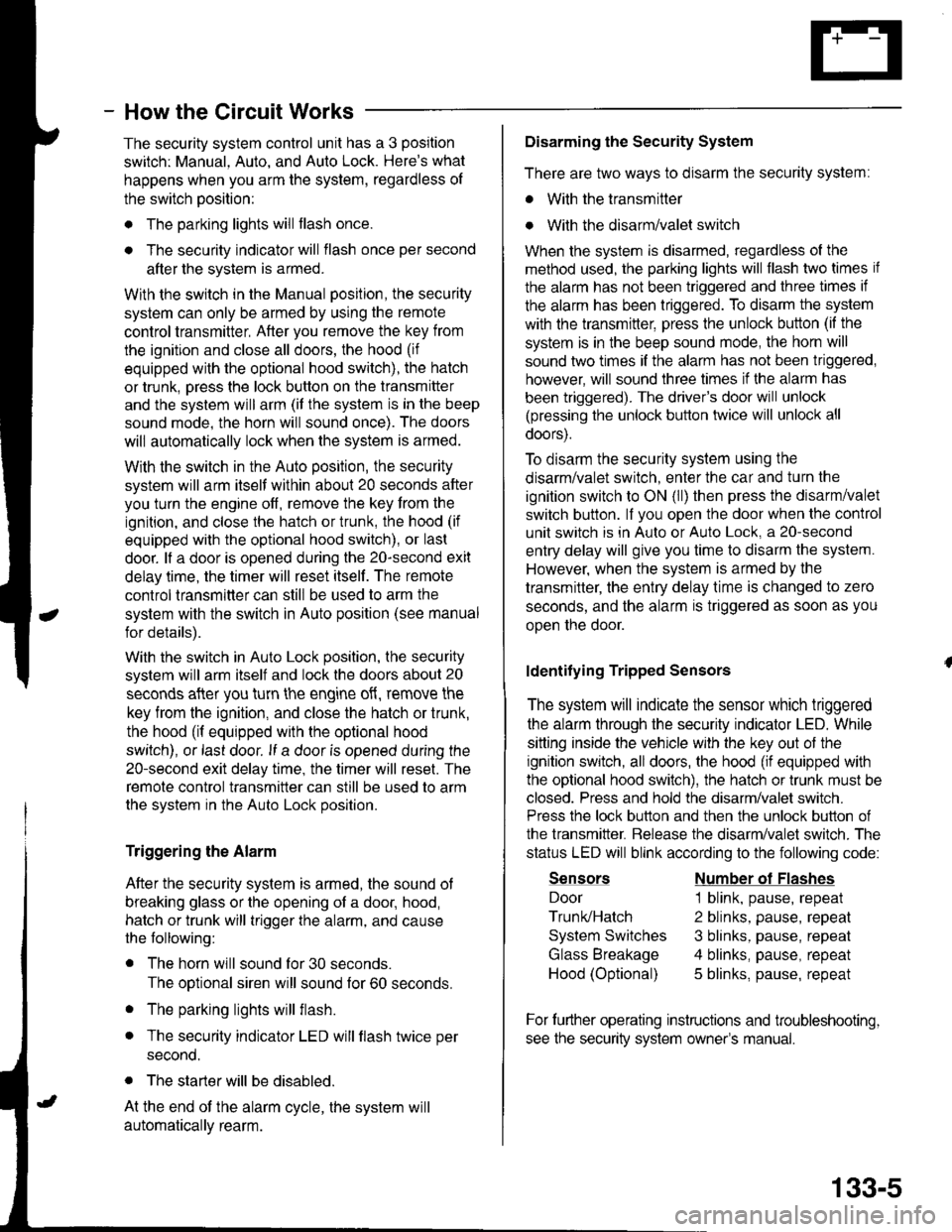
- How the Circuit Works
The security system control unit has a 3 position
switch: Manual. Auto. and Auto Lock. Here's what
happens when you arm the system, regardless ol
the switch position:
o The parking lights will flash once.
. The security indicator will flash once per second
after the system is armed.
With the switch in the Manual position, the security
system can only be armed by using the remote
control transmitter, After you remove the key from
the ignition and close all doors, the hood (if
equipped with the optional hood switch), the hatch
or trunk. Dress the lock button on the transmitter
and the system will arm (if the system is in the beep
sound mode, the horn will sound once). The doors
will automatically lock when the system is armed.
With the switch in the Auto position, the security
system will arm itself within about 20 seconds after
you turn the engine off, remove the key from the
ignition, and close the halch or trunk, the hood (if
equipped with the optional hood switch), or last
door. lf a door is opened during the 2o-second exit
delay time, the timer will reset itself . The remote
control transmitler can still be used to arm the
system with the switch in Auto position (see manual
for details).
With the switch in Auto Lock position, the security
system will arm itself and lock the doors about 20
seconds after you turn the engine of{, remove the
key from the ignition, and close the hatch or trunk,
the hood (if equipped with the optional hood
switch), or last door. lf a door is opened during the
2o-second exit delay time, the timer will reset. The
remote control transmitter can still be used to arm
the system in the Auto Lock position.
Triggering the Alarm
After the security system is armed, the sound ot
breaking glass or the opening of a door, hood,
hatch or trunk will trigger the alarm, and cause
the following:
r The horn will sound for30 seconds.
The optional siren will sound lor 60 seconds.
. The parking lights will flash.
. The security indicator LED will flash twice per
second.
. The starter will be disabled.
At the end of the alarm cycle, the system will
automatically rearm.
Disarming the Security System
There are two ways to disarm the security system:
. With the transmitter
o With the disarm/valet switch
When the system is disarmed, regardless of the
method used, the parking lights will flash two times if
the alarm has not been triggered and three times if
the alarm has been triggered. To disarm the system
with the transmitter, press the unlock button (if the
system is in the beep sound mode, the horn will
sound two times if the alarm has not been triggered,
however, will sound three times if the alarm has
been triggered). The driver's door will unlock
(pressing the unlock button twice will unlock all
doors).
To disarm the security system using the
disarm/valet switch, enter the car and turn the
ignition switch to ON (ll) then press the disarm/valet
switch button. lf you open the door when the control
unit switch is in Auto or Auto Lock, a 2o-second
entry delay will give you time to disarm the system.
However, when the system is armed by the
transmitter, the entry delay time is changed to zero
seconds, and the alarm is triggered as soon as you
oDen the door.
ldentifying Tripped Sensors
The system will indicate the sensor which triggered
the alarm through the security indicator LED. While
sitting inside the vehicle wlth the key out of the
ignition switch, all doors, the hood (if equipped with
the optional hood swilch), the hatch or trunk must be
closed. Press and hold the disarm/valet switch.
Press the lock button and then the unlock button of
the transmitter. Belease the disarm/valet switch. The
status LED will blink according to the following code:
Sensors
Door
Trunk/Hatch
System Switches
Glass Breakage
Hood (Optional)
Number ol Flashes
1 blink, pause, repeat
2 blinks, pause, repeat
3 blinks, pause, repeat
4 blinks, pause, repeat
5 blinks, pause, repeat
For further operating instructions and troubleshooting,
see the security system owner's manual.
133-5