Page 1178 of 1681
Gauge/lndicator/Terminal Location Index
coNNECTOR "8" (C5601
ltrii
rll
coNNECTOR "C" (Css8l
ACHOMETER:rdicates 10O rpm al
OO pulses per minutef the ignition controlrodule {lCM).
81 ------------ 816
ililllllilll
A,/T GEAR POS]TIONINDICATOR SYSTEMS€e page 23-140
c1 ------>cl0
I
Jilliltl
atespage 23-131t Test, page 23-132
^a1(
u;" u
7' /'- /n.u (,w.--
" oe)\r- -7 ttt'-1 r --
I 'l I z{.-a\y' | \-./^l
!t tr--',9I I l\-//11, I t,-\Jl
.r' to"-ei
I :rl
F<
elrle
ENGINE COOLANT TEMPERATUREGauge T€st, page 23-134Sending Unit Test, page 23'134
IECTI GAUGE:
A1 ----> A5
D1-------->D13
ililtl|illl
SPEEOOMETER:lndicates (60 mph at 1025 rpm) or
{60 km/h at 637 rpm) of the
vehicle speed sensor {VSS).
coNNECTOR "A" (C557)
coNNECTOR "D" (C5591
23-121
Page 1179 of 1681
I
rIGauge Assembly
BulbLocations
RIGHT TURN SIGNAL INOICATOR LIGHT ('I.4 WI
BRAKE SYSTEM LIGHT I1.4 WI
DOOR-OPEN INDICATOR LIGHT (1.4 WI
*ABS/SRS INOICATOR LIGHT (1.' W)
LOW FUEL INDICATOR I-IGHT I3.4 W)
SEAT BELT REMINDER LIGHT {1.4 WI
HATCH-OPEN INDICATOR LIGHT {1.4 W}: HarchbackTRUNK'OPEN INDICATOR LIcHT (1.4 W): Sedan
+: On the ABS/SRS printed circuit board
LEFT TURN SIGNAL INDICATOR LIGHT (1.4 WI
CHARGING SYSTEM LIGHT {1,4 WI
A/T GEAR POSITION INDICATOR LIGHT (1.'t2 W x 7)
HIGH BEAM INDICATOR LIGHT I1 .4 \A,
LOW ENGINE OIL PRESSUREINDICATOR LIGHT (1.4 W}
MALFUNCTION INDICATOR LAMP(MtLl (1.4 Wl
LIGHTS13.4 W x 3)REMINDER LIGHT I1.4 WI
cRursE LTGHT | 1.4 Wt
23-122
Page 1182 of 1681
J
BLKYEL
YEUBLU
A8SN0.53 (104) FUSE CONTROLlFrofi page 23A'123) UNIT
VV
II
tltlWHT/GFN BLU/REO
lonWHT€IU
I
I
I
\?
ALTERNATOR
lo'PNK
J
HAZAROWARNINGswtTcH
MENTENANCEREMINDERLIGHT0.4v,/i
lo'PNK
II
I
J
MAINTENANCEREMINDERUNIT
| 011
YEUREO
I
T
P"-:
)-
BLK
I:
G201G401
LOWENGINE OILPFESSUREINDICATORLIGHT0.4w)
23-125
)J
Page 1184 of 1681
{
Disassembly
NOTE: Handle the terminals and Drinted circuit boards carelully to avoid damaging them.
FUEL GAUGEMOUNTING SCBEW {x 3l
e
o
SPEEDOMETER MOUNTING SCREW (x 4)ENGINE COOLANTTEMPERATURE {ECT)GAUGEMOUNTING SCREW {x 3}
t)ENGINE COOLANTTEMPERATURE IECTIGAUGE UNITTest, page 23-134TACHOMETEF UNITSpecification, page 23-121
SRS PRINTEDCIRCUIT BOARD
d'dP
METER HOUSTNG
FUEL GUAGE UNITTest, page 23 131
'
/*'
r@/ ror
6rH"
SPEEDO/ODO/TRIP METER UNTT' SPEEDOMETERSpecification, page 23-121Troubleshooting, Page 23_128. ODOMETERTroubleshooting, page 23-128. TRIP METERTroubleshooting, Page 23 128
TACHOMETER MOUNTING SCREW {x 3)
PRINTED CIRCUIT BOARD
It
23-127
Page 1185 of 1681

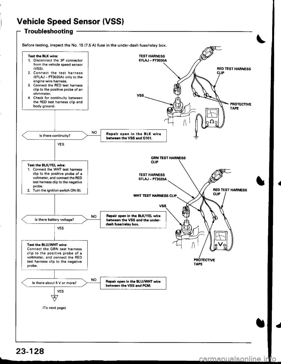
Vehicle Speed Sensor (VSSI
Troubleshooting
{To next page)
REO TEST HARNESS
PBOTECTIVETAPE
Test tho 8LK wiro:1. Disconnect the 3P connectorfrom the vohicle speed sensor(vss).
2. Connect the test harness(07LA,J - PT3020A) only to theengine wire harnoss.3, Connect the RED test harnessclip to the positive probe of anohmmel€r.4. Check for continuity betwoenthe RED test harness clip andbody ground.
Roplir op.n in th. BLK wirob.tw..n tha VSS .nd G101.
To3t thc BLK/YEL wiro:1. Conn6ct th€ WHT test harnessclip to the positive prob€ of avoltmeter, and connect the REDt€st harness clip to the nogativeprobe.2. Turn the ignition switch ON (lll.
R.p.lr op.n In tho BLK/YEL wirebrtw..n th. VSS and th. under-dr.h tu../r.l!y box.
Tort th. BLU/WHT wiro:Connect the GRN test harnessclip to the positive prob€ ot avoltmeter, and connect the REDtest harness clip to the nggatjveprobe.
Roprh op.n in th. 8LU/WHT wireb.tw.on tho VSS lnd PCM.ls there about 5 V or more?
Before testing, inspect the No. 15 (7,5 A) fuse in the under-dash fuse/relay box.
GRN TESTCLIP
TEST HARNESSOTLAJ - PT3O2OA
w'{T TES? HARIVESS CLIP
TAPE
23-128
Page 1187 of 1681

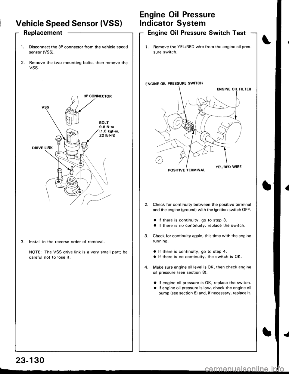
1. Disconnect the 3P connector from the vehicle speed
sensor (VSSl.
2. Remove the two mounting bolts, then remove the
VSS.
3P CONNECTOR
BOLT9.8 N.m(1.O kgf.m,22 tbt,ltl
DRIVE LINK
3.Install in the reverse order of removal.
NOTE: The VSS drive link is a very small part;
careful not to lose it.
DC
Vehicle Speed Sensor (VSS)
Engine Oil Pressure
lndicator System
ReplacementEngine Oil Pressure Switch Test
23-130
E-_
1 . Remove the YEL/RED wire trom the engine oil pres-
sure swlrcn.
ENGINE OIL PBESSURE SWITCH
Check for continuity between the positive terminal
and the engine (ground) with the ignition switch OFF.
a lf there is continuity, go to step 3.
a lf there is no continuity, replace the switch.
Check lor continuity again, this time with the engine
running.
a lf there is continuity, go to step 4.
a lf there is no continuity, the switch is OK.
Make sure engine oil level is OK, then check engine
oil pressure (see section 8).
a lf engine oil pressure is OK, replace the switch.
a lf engine oil pressure is low, check the engine oil
pump (see section 8) and, iI necessary, replace it.
2.
3.
POSITIVE TERMINAL
Page 1191 of 1681

Engine Coolant Temperature (ECT) Gauge
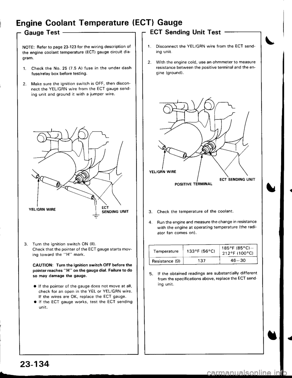
Gauge Test
NOTE: Refer to page 23-123 for the wiring description of
the engine coolant temperature (ECT) gauge circuit dia-
gram.
1. Check the No. 25 (7.5 A) fuse in the under-dash
fuse/relay box before testing.
2. Make sure the ignition switch is OFF, then discon-
nect the YEL/GRN wire trom the ECT gauge send-
ing unit and ground it with a jumper wire.
YEL/GRN WIRESENDING UNIT
Turn the ignition switch ON (ll).
Check that the pointer of the ECT gauge starts mov-
ing toward the "H" mark.
CAUTION: Turn the ignition switch OFF before the
pointer reaches "H" on the gauge dial. Failure to do
so may damage the gauge.
a lf the pointer of the gauge does not move at all,
check lor an open in the YEL or YEL/GRN wire.
lf the wires are OK, replace the ECT gauge.
a lf the ECT gauge works, test the ECT sending
unrt.
ECT Sending Unit Test
Disconnect the YEL/GRN wire from the ECT send-
ing unit.
With the engine cold, use an ohmmeter to measure
resistance between the positive terminal and the en-
gine (ground).
Check the temperature ol the coolant.
Run the engine and measure the change in resistance
with the engine at operating temperature (the radi-
ator fan comes on).
5. It the obtained readings are substantially different
from the sDecifications above, replace the ECT send-
Ing unrt.
POSITIVE TERMINAL
Temperature133oF (56oC)1850F (85.C)-
212.F (100'C)
Resistance {O)13746-30
23-134
Page 1202 of 1681

Replacement
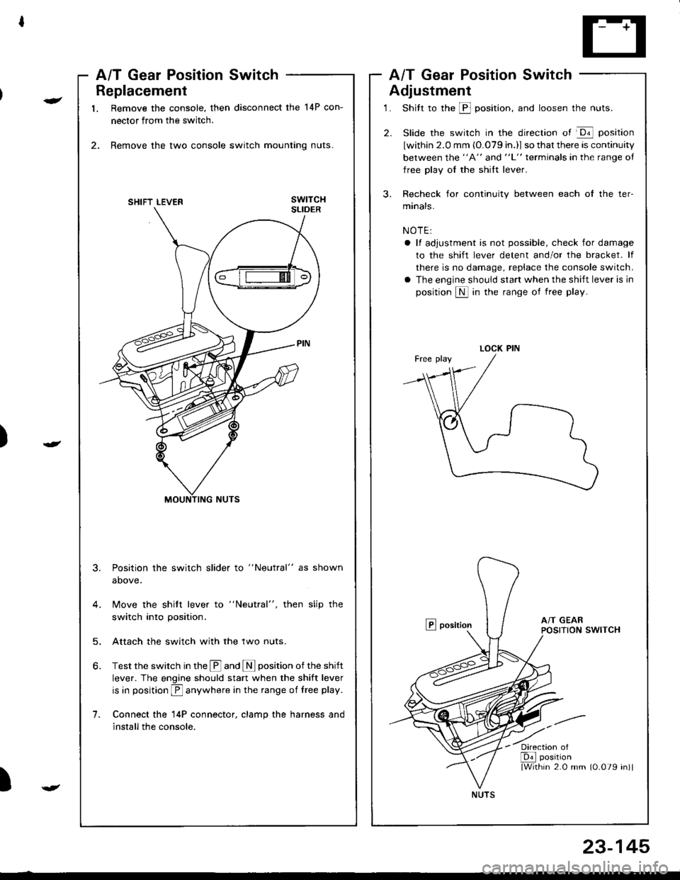
1. Remove the console. then disconnect the 14P con-
nector from the switch.
2. Remove the two console switch mounting nuts.
3.
1.
Position the switch slider to "Neutral" as shown
above.
Move the shitt lever to "Neutral", then slip the
switch into position.
Attach the switch with the two nuts.
Test the switch in the @ and I position of the shift
lever. The engine should start when the shift lever
is in position E anywhere in the range of free play.
Connect the l4P connector, clamp the harness and
install the console.
5.
)
-
A/T Gear Position SwitchA/T Gear Position Switch
Adjustment
1. Shitt to the @ position, and loosen the nuts.
2. Slide the switch in the direction of @ position
lwithin 2.0 mm (O.079 in.)l so that there is continuity
between the "A" and "L" terminals in the range oI
free play oI the shift lever.
3. Recheck for continuity between each of the ter-
manals.
NOTE:
a ll adjustment is not possible, check for damage
to the shift lever detent and/or the bracket. lf
there is no damage, replace the console switch.
a The engine should start when the shift lever is in
position S in the range of free play.
E position
)
LOCK PIN
'/ia
NUTS
23-145