Page 796 of 1681

- With the ignition switch ON(lll, the ABS indicator doesnot go off.- With the SCS s€.vice connec-tor connected lsee page 19-37), OTCS 11, 13, 15, 17 areindicated.
Check for a short to pow6r in thewheel sensor circuii:1. Disconnect the ABS controlu nit 22P connector.2. Start the engine.3, Measure the voltage betweenthe appropriate wheel sensor(+) circlit terminal and bodyground (see table).
Repair short to power in the {+)circuit wire between the ABScontrol unil and the approprialewheel sensor.
ls there 2 V or more?
Check for a short to body groundin th6 wheel sensor circuil:Check tor continuity between theappropriate wheel sensor (+) cir-cuit terminal and body ground(see table).. Ropair short lo body ground inthe {+) or {-l circuit wirebetween tho ABS contlol unitand th6 .ppropriate whe€l sen-
. Roplaco the .ppropliate wheelsensot.
ls there continuity?
Check for an open in the wheelsensor circuit:Check the resistance between theappropriate wheel sensor (+) and1-) circuit terminals (see table).
Ropair open in the {+) or (-} cir-cuit wire, or 3hort to the l+) cir-cuit wire in the l-l circuit wirebetween tho ABS control unitand th6 appropriate whgel 3en-
Replace th6 appropdate wh€elsensot.
ls the resistance OK?FronvRear: 450 - 2,050 O/20"c (68.F)
NOTE: lf you do not erase the DTC, the ABS indicator will not go off until vehicle speedexceeds 6 mph (10 km/h).
ABS CONTNOL UNIT 22P CONNECTOF
FLw {+l {GRN/ORN) FRw {+} (GRN/BLKI
oTcAppropriate Terminal
(+)Side( )side
11 (Right-front)No. 9: FRW (+)No. 8: FBW {-)
13 (Left'front)No.7: FLW (+)No.6: FLW 1-)
l5lBight-rear) iNo. 19:RRW (+!o. 20: RBW (-
17 (Left'r€af)17: RLW {+',1o. 18: RLW (-Wire side of lemale terminals
FLW (+) (GRN/ORN) FRW l+){GRN/BLK)
FLw l+l (GRN/ORNI FRW {-) {GRN}
FLW t-l(+l (GRN/BLKI
RL(-I {BLU/YELI
RLW l-) (GBY) RRW (+) (GRN/YEL)
Check for loose ABS control unitconnectors. lf necessary. substi-tute a known-good ABS controlunii and recheck.
RLW {+l (LT BLUI
RLw (+l {LT BLU}
-t(o
___r
l'!*
6l89l01t
1417t8t920
| ***-t
(()
Y
Troubleshooting
DTC 1 1, 13, 15, 17 : Wheel Sensor (open/short to body ground/short to power)
\
L
9-44
\
Page 806 of 1681
Troubleshooting
DTG 52: Motor Stuck OFF lcont'd)
PUMP ITIOTOR BELAY CONNECTOf,
JUMPERWIRE
Terminel side of female i€rminals
aBs oo tnol ut{tT 12P cof{f{EGToR
Wire side of lemale terminals
I
.t!
Ch.ck tor !n op.n in thc PMR cir-
cuit:1. Connoct tho pump motor relay
connector terminal No. 2 toNo.3 with a iumpor wir6.2, M€asure th6 voltage betw6entho A8S control unit 12P con-nector terminal No. 12 andbody ground.
R.p.ir op.n In th. wir. batw..nth. und.r-hood ABS tu../r.l.Ybox lnd th. ABS codrol unil.
Check lor a rho to pow.r in th.PMR circuii:1. Removo the jumper wire frompump motor relay connedor.2. Start the engine.3. ireasur6 the voltage betwoenth6 ABS control unit 12P con-nector terminal No. 12 8ndbody ground.
R.p.ir .hort to pow.r In th. wil.
brtwa!n lh. und..-hood ABSfur./r.l.y box rnd th. A8S con-trol unit.
ls th€re batt€ry voltage?
lf tha problam occura again,r.pllce th. ABS control unit.
Page 813 of 1681

Modulator Unit
Removal/lnstallation
CAUTION:
. Do not spill brake fluid on lhe vehicle; it may damage the paint; il brake fluid does contact the paint, wash it offimmediately with water.
. Tak€ care notto damage or delorm the brake lines during removal and installation.. To provont the brake fluid ftom flowing, plug and cover the hos€ ends and ioints with a shop towel or equiyalent material.
Removal
1. Disconnect the modulator unit and DUmD motor connectors.
2. Disconnect the brake lines, then remove the modulator unit.
Installation
1. lnstall the modulator unit, then connect the brake lines. Tighten the flare nuts to 15 N.m (1.5 kgf.m, 11 lbf.ft).2. Connect the modulator unit and pump motor connectors.
3. Bleed the brake system, starting with the front wheels.
4. Start the engine, and check that the ABS indicator goes off.
5. Test-drive the vehicle, and check that the ABS indicator does not come on.
From master cylinder
from master cylinderprimary side
PUMP MOTOB CONNECTOR
MOUNT
UNlT
MODULATOR UNIT CONNECTOR
toright front
8 mm EOLT22 N.m {2.2 kg[.m, 16 lbl.ftl
6 mm NUT9.8 N.m 11.0 ks{.m,7.2lbtftl
9-6
Page 814 of 1681
ABS Control Unit
RemovaUlnstallation
1. Remove the right quarter trim panel.
2. Disconnect the ABS control unit connectors.
3. Remove the ABS control unit.
Pulsers/Wheel Sensors
Inspection
/t
l\
I
Check the front and rear pulser for chipped or dam-
aged teeth.
Measure the air gap between tho wheel sensor and
pulser sllthe way around while rotating the pulser.
Standard: 0.4 - 1.0 mm (0.02 - 0.04 in)
NOTE: lf the gap exceeds 1.0 mm (0.04 in), the
probability is a distorted suspension arm which
should be reDlaced.
Front/R..1
L-TJ
.t-
t=
l-
Et-E_
Install the ABS control unit in the reverse order of
removal.
Start the engine, and check that the ABS indicator
goes off.
Test-drive the vehicle, and check that the ABS indi-
cator does not come on.
19-62
Page 995 of 1681

SYMPTOMREMEDY
Hot air tlow is low.Blower motor runs, but one or more
speeds are inoperative.
Follow the flowchart (see page 21-9).
Blower runs propetly.Check for the following:. Clogged heater duct
. Clogged heater outlet
. Incorrect door Position
No hot air tlowBlower motor does not run at all.Follow the flowchart {see page 21-11}
Blower motor runs.Check for the following:
. clogged heater duct
. Clogged blower outlet. Clogged heatet valve
. Faultv air mix door
. Heater valve cable adjustment lsee page 21-27].
. Air mix control cable adiustment {see page 21-27)
. Faulty thermostat (see section 10)
. Clogged evsporator (with air conditioning)
. Frozen evaDorator (with air conditioning)
Mode control motor does not run, or one or more mooes are
inoDeratave.
Follow the flowchart (see page 21-14).
Recirculation control door does not change between FRESH
and RECIRCULATE.
Follow the flowchart {see page 21-17).
Troubleshooting
Symptom Chart
NOTE: Check the engin€ coolant level and allow the engine to warm up before troubleshooting'
21-8
v
Page 1009 of 1681

Heater Unit
Replacement
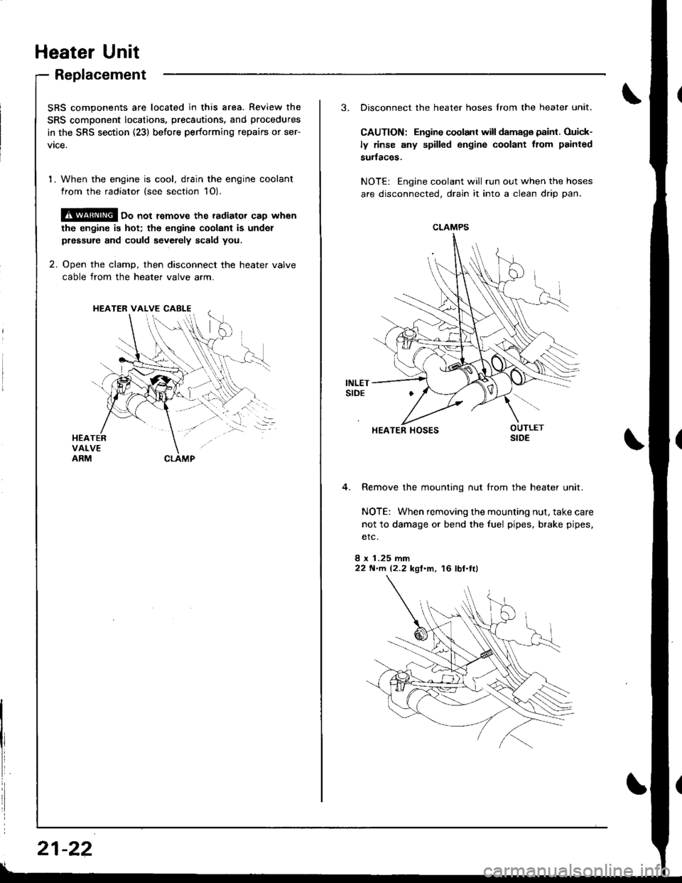
SRS components are located in this area. Review the
SRS component locatio.s, precautions, and procedures
in the SRS section (23) before performing repairs or ser-
vtce.
1. When the engine is cool, drain the engine coolant
from the radiator (see section 1O).
@ oo not remove the radiator cap when
the engine is hot; the engine coolant is undol
prsssure and could sevdely scald you.
2. Ooen the clamD, then disconnect the heater valve
cable from the heater valve arm.
HEATER VALVE CABI-E
I
i
21-22
3. Disconnect the heater hoses lrom the heater unit.
CAUTION: Engine coolant will damaga paint. Ouick-
ly rinse any spilled engine coolant from painted
sudaces.
NOTE: Engine coolant will run out when the hoses
are disconnected, drain it into a clean drip pan.
4. Remove the mounting nut from the heater unit.
NOTE: When removing the mounting nut, take care
not to damage or bend the fuel pipes, brake pipes,
etc.
8 x 1.25 mm22 N'llt. 12.2 kgl'm, 16 lbl.tl)
CLAMPS
HEATER HOSES
Page 1010 of 1681

.J
5.
6.
7.
8.
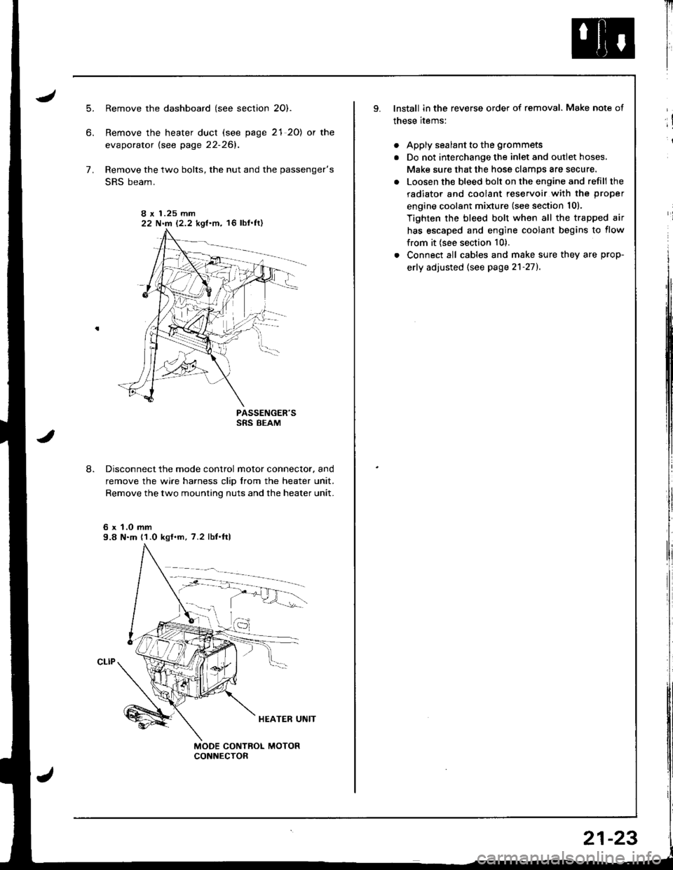
Remove the dashboard (see section 2O).
Remove the heater duct (see page 21 20) or the
evaporator lsee page 22-261.
Remove the two bolts, the nut and the passenger's
SRS beam.
PASSENGER'SSRS BEAM
Disconnect the mode control motor connector. and
remove the wire harness clip from the heater unit.
Remove the two mounting nuts and the heater unit.
6 x 1.0 mm9.8 N.m (1.0 kgf.m, 7.2 lbf.ftl
I r 1.25 mm22 N.m 12.2 kgf.m, 16 lbf'ft)
Il
I
I
lnstall in the reverse order of removal. Make note of
these items:
. Apply sealant to the grommets
. Do not interchange the inlet and outlet hoses.
Make sure that the hose clamps are secure.
. Loosen the bleed bolt on the engine and refill the
radiator and coolant reservoir with the proper
engine coolant minure (see section 10).
Tighten the bleed bolt when all the trapped air
has escaped and engine coolant begins to flow
from it (see section 10).
. Connect all cables and make sure they are prop-
erly adjusted (see page 2'l-271.
;!
i
21-23
Page 1025 of 1681

J
Troubleshooting
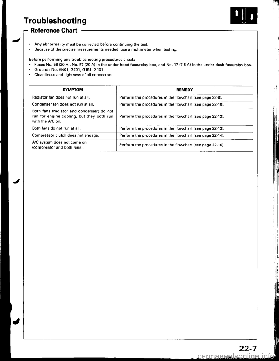
Reference Chart
. Any abnormality must be corrected before continuing the test.. Because of the precise measurements needed, use a multimeter when testing.
Before performing any troubleshooting procedures check:. Fuses No, 56 (20 A), No. 57 (20 A) in the under-hood fuse/relay box, and No. 17 {7.5 A) in rhe under-dash fuse/relay box.. Grounds No. G401, G201, G151, G101. Cleanliness and tightness of all connectors
I'IT
I
I
SYMPTOMREMEDY
Radiator fan does not run at all.Perform the procedures in the flowchart {see page 22-8).
Condenser fan does not run at all,Perform the procedures in the flowchart (see page 22-1O1.
Both fans {radiator and condenser) do not
run for engine cooling, but they both run
with the IVC on.
Perform the procedures in the tlowchart (see page 22-12).
Both fans do not run at all.Perform the procedures in the flowchart (see page 22-13).
Compressor clutch does not engage.Perform the procedures in the flowchart (see page 22-14).
l'lc system does not come on
{compressor and both fans).Perform the procedures in the flowchart (see page 22-15).
22-7