1998 HONDA INTEGRA throttle valve
[x] Cancel search: throttle valvePage 315 of 1681

ldle Control System
Fast ldle Thermo Valve (A/T model onlylFast ldle I nermo valve (A/ | mooel
Description
To prevent erratic running when the engine is warming
up. it is necessary to raise the idle speed. The fast idle
thermo valve is controlled by a thermowax plunger.
When the engine is cold, the engine coolant surround-
ing the thermowax contracts the plunger, allowing addi
tional air to be bvoassed into the intake manifold so that
the engine idles taster. When the engine reaches operat-
ing temperature, the valve closes. reducing the amount
of air bypassing into the manifold.
FAST IDLE THERMO
VALVE
VALVE
wAx
Inspection
NOTE: The fast idle thermo valve is factory adiusted; it
should not be disassembled.
1. Remove the intake air duct from the throttle body.
2. Start the engine.
3. Put your finger over the lower port in throttle body
and make sure that there is air flow with the engine
cold {engine coolant temperature below 86'F, 30"c).
LOWERPORT
lf there is no air flow, replace the last idle thermo
valve and retest.
Start the engine. Hold the engine at 3,000 rpm with
no load (in Park or neutral) until the radiator fan
comes on, then let it idle.
Check that valve is completely closed. lf not, air suc-
tion can be felt at the lower port in the throttle body.
l{ any suction is felt, the valve is leaking. Check
engine coolant level and for air in the engine
coolant system (see section 10). It OK, replace the
fast idle thermo valve and recheck.
5.
{1.0 kg.m,7.2lbftl
l
11-110
lL.�
Page 333 of 1681

r
Intake Air System
System DescriptioSystem uescnpllon
The system supplies air for all engine needs. lt consists of the intake air pipe. Air Cleaner (ACL), intake air duct, Throttle
Body (TB), ldle Air Control (lAC) Valve, fast idle thermo valve (A,/T model only), and intake manifold.
A resonator in the intake air pipe provides additional silencing as air is drawn into the system.
B18Cl engine lB18Bl, B18C5 enginos does not havs the IAB systeml:
IABCONTROLsollNolDVALVE
VARIOUSSENSORS
IABCONTROLDIAPHRAGM
IiITAKEAIR PIPE
INTAKE MANIFOLDINTA|(EAIRDUCT
RESONATOR
Page 335 of 1681

l-
Intake Air System
LOCKNUT
DEFLECTION10-12mmBIA- 112in.l
lf deflection is not within specs, loosen the locknut,
turn the adjusting nut until the deflection is as spec-
ified, then retighten the locknut.
With the cable properly adiusted, check the throttle
valve to be sure it opens fully when you push the
accelerator pedal to the floor. Also check the throt-
tle valve to be sure it returns to the idle position
whenever you release the accelerator pedal.
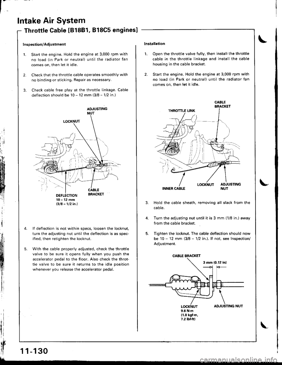
Throttle Cable IB18B1, 818C5 engines]
Inspection/Adiustment
1. Start the engine. Hold the engine at 3,000 rpm wirh
no load (in Park or neutral) until the radiator tan
comes on, then let it idle.
2. Check that the throttle cable operates smoothly wilh
no binding or sticking. Repair as necessary.
3. Check cable free play at the throttle linkage. Cable
deflection should be 10 - 12 mm (3/8 - 'l12 in.l
ADJUSTINGNUT
t
il
qr
ll1 1-130
!!
TING NUT
\lnstallation
1. Open the throttle valve fully, then install the throttle
cable in the throttle linkage and install the cable
housing in the cable bracket.
2. Start the engine. Hold the engine at 3,000 rpm with
no load (in Park or neutral) until the radiator fan
comes on, then let it idle.
INNER CABLE
Hold the cable sheath, removing all slack from the
caote.
Turn the adjusting nut until it is 3 mm {1/8 jn.) away
from the cable bracket.
Tighten the locknut, The cable deflection should now
be 10 - '12 mm (3/8 - 'll2 in.). lf not, see Inspection/
Adjustment.
3 mm 10.12 inl
u
4.
AD
\
JUSLOCKNUT9.8 N.m(1.0 kgt.m,7,2lbl.ttl
CABI.E
CABI,E BMCKET
Page 336 of 1681

't.
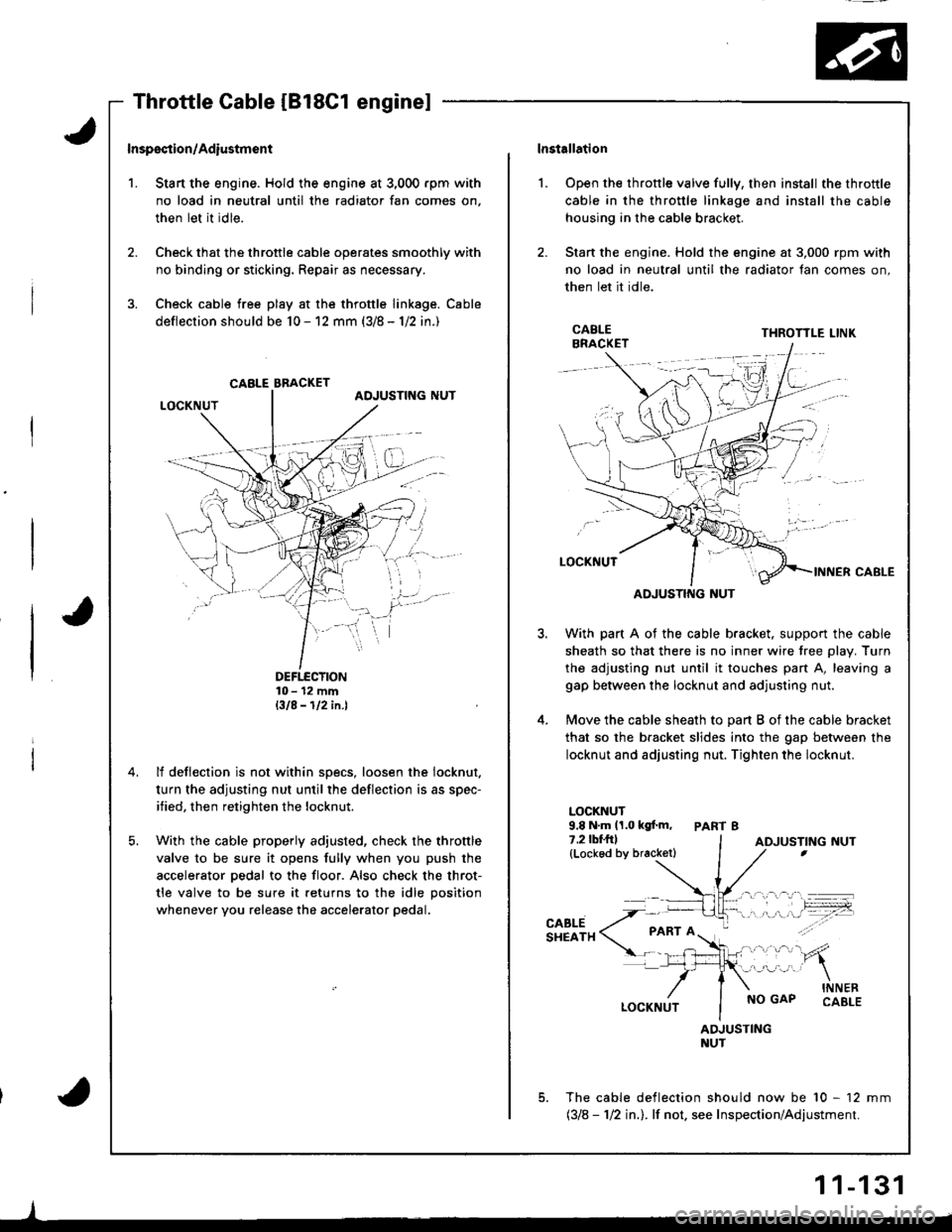
Inspsction/Adiustmsnt
Stan the engine. Hold the engine at 3,000 rpm with
no load in neutral until the radiator fan comes on,
then let it idle.
Check that the throttle cable operates smoothly with
no binding or sticking. Repair as necessary.
Check cable free play at the throttle linkage. Cable
deflection should be 10 - 12 mm (3/8 - 1/2 in.)
DEFTECTION10- 12 mmBIA-112in.l
lf deflection is not within specs, loosen the iocknut.
turn the adjusting nut until the deflection is as spec-
ified, then retighten the locknut.
With the cable properly adjusted, check the throttle
valve to be sure it opens fully when you push the
accelerator pedal to the floor. Also check the throt-
tle valve to be sure it returns to the idle position
whenever you release the accelerator pedal.
CABLE BBACKET
lnstallation
Open the throttle valve fully, then install the throttle
cable in the throttle linkage and install the cable
housing in the cable bracket.
Stan the engine. Hold the engine at 3,000 rpm with
no load in neutral until the radiator fan comes on,
then let it idle.
l.
3.
5.
CABLEBRACKETTHROTTLE LINK
ADJUSTING NUT
With part A of the cable bracket. support the cable
sheath so that there is no inner wire tree plav. Turn
the adjusting nut until it touches part A, leaving a
gap between the locknut and adjusting nut.
Move the cable sheath to oart B of the cable bracket
that so the bracket slides into the gap between the
locknut and adjusting nut. Tighten the locknut.
LOCKNUT9.8 N.m 11.0 kgf.m, PART 87.2lbf.frl(Lockod by bracketl
CABLESHEATH
NO GAPINNERCABLE
ADJUSTINGNUT
The cable deflection should now be 10 - 12 mm(318 - 112 in.l. lf not. see Inspection/Adjustment.
ADJUSTING NUT
1 1-131
Page 337 of 1681

In
Intake Air System
Throttle Body
$;
Description
The throttle body is of the single barrel side-draft type.
The lower portion of the throttle valve is heated by
engine coolant from the cylinder head. The idle adjusting
screw which increases/decreases bypass air is located on
the top ot the thronle body.
IDLE ADJUSTINGSCREW
THROTTLESTOP SCREW(Non-adjustable)
FAST IDLE
| | .o clearance. THRoTTLE SToP scREw
{ | | _ .lDonotadiust)
| | y:::::::T,"9":::.'"Tl::f ,::i1::"1" fllyll-'n"
VALVE {A/T model onlv}
Inspection
1. Start the engine. Hold the engine at 3,000 rpm with
no load {in Park or neutral) until the radiator fan
comes on, then let it idle.
2. Stop the engine, and check that the throttle cable
operates smoothly without binding or sticking.
. lf the throttle body pon is clogged, clean it with
carburetor cleaner.
. lf there are any abnormalities in the above steps,
check for:
Excessive wear or play in the throttle valve shaft.- Sticky or binding throttle lever at full close posi-
tion.- Clearance between throttle stop screw and throt-
tle lever at fullclose position.
81881, Bl8Cl engines:
There should beno clearance.
818C5 engine:THROTTLE LINK
There should be
throttle valve shaft or if the shaft is binding or sticking.
glL-
Page 338 of 1681

Disassembly
NOTE:
. The throttle stoD screw is non-adiustable.
. After reassembly, adjust the th rottle ca ble (page 11-130, 131),andA/Tthrottlecontrol cable (section l4)Ior cars with A/T.. The TP sensor is not removable.
IOLE ADJUSTINGSCREW
FAST IDLETHERMOVALVE {A/T model onlylInspectaon, page 1 1-l 10
-l
12.2 kgf.m, 16 lbf.ft)
1 1-133
Page 420 of 1681

Description
\J
t{
{
14-3
The automatic transmission is a combination of a 3-element torque converter and triple-shalt electronically controlled
automatic transmission which provides 4 speeds forward and 1 speed reverse. The entire unit is positioned in line with
the engrne.
Torque Converter, Gears, and Clutches
The torque converter consists of a pump, turbine, and stator, assembled in sigle unit. The torque converter is connected to
the engine crankshaft so they turn torether as a unit as the engine turns. Around the outside of the torque convener is a
ring gear which meshes with the starter pinion when the engine is being started. The entire torque converter assembly
serves as a flywheel while transmitting power to the transmission mainshaft.
The transmission has three parallel shafts; the mainshaft. the countershaft, and the sub shaft. The mainshaft is in-line with
the engine crankshaft.
The mainshaft includes the 1st, and 2ndl4th clutches,and gear for 3rd, 2nd, 4th, reverse, and 1st. (3rd gear is integral with
the mainshaft, while reverse gear is integral with the 4th gear.)
The countershaft includes the 3rd clutch and gears for 3rd,2nd, 4th, reverse, 1st, and parking. Reverse and 4th gears can
be loched to the countershaft at its center,providing 4th gear or reverse, depending on which way the selector is moved.
The sub-shaft includes the 1st-hold clutch and gears fo 1st and 4th.
The gears on the mainshaft are in constant mesh with those on the countersahft and sub-shaft.When certain combinations
of gears in the transmission are engaged by clutches. power in transmitted from the mainshaft to the countershaft via the
sub-shaft to orovude oil, lo'1. E, E. and E.
Electronic Control
The electronic control svstem consists of the Transmission Control Module (TCM), sensors, and four solenoid valves.
Shilting and lock-up are electronically controlled for comfortable driving under all conditions.
The TCM is located below the dashboard, behind the lelt side kick panel on the driver's side.
Hydraulic Control
The valve bodies include the main valve body, the secondary valve body, the regulator valve body, the serbvo body, and
the lock-up valve body, through the respective separator plates, They are bolted to the torque converter housing,
The main valve body contains the manual valve, the 1-2 shift valve, the 2-3 shitt valve, the Clutch Pressure Control
lCPC) valve, the 4th exhaust valve, the reliel valve, and the ATF pump gears.
The secondary valve body contains the 4-3 kick-down valve, the 3-2 kick-down valve, the 2-3 orifice control valve, the
3-4 shift valve, the orilice control valve, the modulator valve, and the servo control valve.
The regulator valve body contains the pressure regulator valve, the lock-up control valve, the torque converter check
valve, and the cooler check valve.
The servo body contains the servo valve, which is integrated with shift fork shaft, the throttle valve B, and the accumula-
tors.
The lock-up valve body contains the lock-up shift valve and the lock-up timing B valve, and is bolted to the regulator valve
ooqy.
Fluid from the regulator passes through the manual valve to the various control valves.
Shift Control Mechanism
Input to the TCM from various sensors located throughout the car determines which shift control solenoid valve should
be activated. Activating a shitt control solenoid valve changes modulator pressure, causing a shift valve to move. This
pressurizes a line to one ol the clutches, engaging that clutch and its corresponding gear.
Lock-uD Mechanism
In @ position, in 2nd, 3rd and 4th, and @ position in 3rd, pressurized fluid can be drained lrom the back oI the tor-
que converter through a fluid passage, causing the lock-up piston to be held against the torque converter cover. As this
takes place, the mainshaft rotates at the same speed as the engine crankshaft. Together with hydraulic control, the TCM
optimizes the timing of the lock-up mechanism.
The lock-up valves controlthe range of lock-up according to lock-up control solenoid valves A and B, and throttle valve B.
When lock-up control solenoid valves A and B activate, modulator pressure changes. Lock-up control solenoid valves
A and B are mounted on the torque converter housing, and are controlled by the TCM.
(cont'd)
Page 444 of 1681

Servo Body
The servo body is located on the secondary valve body.
The servo body houses the servo valve (integrated with the shift fork shaft), the throttle valve B, and the accumulator pis-
tons.
THROTTLE
Accumulator Pistons
The accumulator pistons are assembled in the servo body and right side cover. The 1st-hold clutch accumulator piston is
in the right side cover, and the 1st,2nd,3rd, and 4th accumulator pistons are in the servo bodv.
lST.HOLD ACCUMULATORPISTON
lST ACCUMUI.ATOR
2ND ACCUMULA3RO ACCUMULATOR PISTON
THBOTTLE LONG VALVE
RIGHT SIDE COVER
14-27