1998 HONDA INTEGRA throttle valve
[x] Cancel search: throttle valvePage 211 of 1681

Gomponent Locations
Index (cont'dl
THROTTLE BODY {TBIInspection, page 1 1'132
Disassembly, page 1 1-133
THEOTTLE CABLEInspection/Adjustment, pages 11-130, 131
lnstallation, Pages 11 130' 131AIR CLEANER IACL)Replacement, Page 11 129
RESONATOR
INTAKEAIRBYPASS {IAB)CONTROLDIAPHRAGM(818C1 engine onlylTroubleshooting,page 11-135
i-)
i--- / /
i rl
l'-' i
INTAIR
POSITIVE CRANKCASEVENTILATION (PCV) VALVEInspection, page 11'140
BYPASS IIAB}CONTROLSOLENOIDVALVE (818C1 ongine only)
Troubleshootrng,page 11-135
PGM-FIMAIN RELAYRelayTesting, Page 11 124
Troubleshooting, Page 1 1-1 25
L
ENGINE CONTROL MODULE IECM}
Tro!bleshooting, Page 11 50
SERVICE CHECK CONNECTOR {2P)
Troubleshooting Procedures, page 1 1'32
DATA LINK
1 1-6
\'
Page 241 of 1681

Troubleshooting
Troubleshooting Procedures (cont'd)
Symptom Chart
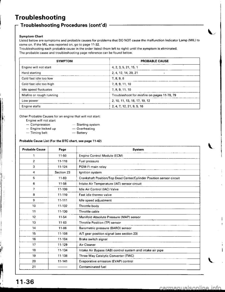
Listed below are symptoms and probable causes for problems that DO NOT cause the malfunction Indicator Lamp (MlL) to
come on. lf the MIL was reported on, go to page 11-32.
Troubleshooting each probable cause in the order listed (from left to right) until the symptom is eliminated.
The probable cause and troubleshooting page relerence can be found below.
Other Probable Causes for an engine that will not start:
Engine will not sta rt- Compression- Engine locked up- Timing belt
\_
- Starting system- Overheating- Battery
'4,
It
Probable Cause List (For the DTC chart. see page 11-421
Probable CausePageSystem
111-50Engine Control Module (ECM)
211118Fuel pressure
311-124PGM-Fl main relay
4Section 23lgnition system
51 1-83Crankshaft Position/ToD Dead Center/Cylinder Position sensor circuit
11-58Intake Air Temperature (lAT) sensor circuit
71 '�t- 100ldle Air Control (lAC) Valve
811110Fast idle thermo valve
I11lllldle speed adjustment
'1011-132Throttle body
111 1-130Throttle cable
1211-54lvlanifold Absolute Pressure {MAP) sensor
IJ1163Throttle Position {TP) sensor
1411-86Barometric pressure (BARO) sensor
1 '1 106A/T gear position signal {see section 23)
16'1 1 104Brake switch signal
1711 129Air Cleaner
181 1- 134Intake Air Bypass {lAB} control system and intake air pipe
19'1 1 138Three Way Catalytic Convener (TWC)
2011-141Evaporative emission (EVAP) control
21Contaminated fuelll ll 21 | - | cont"-in"t"o tu"
11 l-
I
,l 11-36
-
SYMPTOMPROBABLE CAUSE
Engine will not stan4, 2, 3,5, 21, 15, 1
Hard starting2, 4, 12, 14,20,21
Cold fast idle too low
Cold fast idle too high7, 8, 9, 11, r0
ldle speed fluctuates7,8,9,11,10
Misfire or rough runningTroubleshoot for misfire on pages 11-78,79
Low power2, 10,'t1, 13, 14, 17, 19, 12
Engine stalls2, 4,1 , 12,21,9, 5, 16
Page 243 of 1681

Troubleshooting
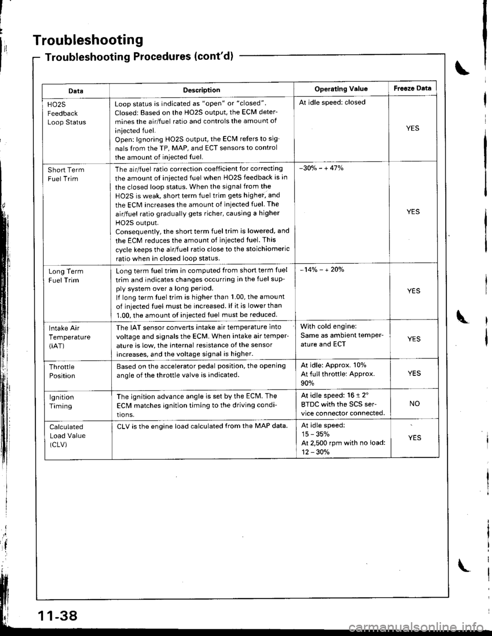
DataDescriotionOperating ValueFreeze Data
HO25
Feedback
Loop Status
Loop status is indicated as "open" or "closed".
Closed: Based on the H02S output, the ECM deter-
mines the airlfuel ratio and controis the amount of
iniected fuel.
Open: lgnoring HO2S output, the ECM refers to sig-
nals from the TP, MAP, and ECT sensors to control
the amount of iniected fuel.
Al idle speed: closed
YES
Short Term
Fuel Trim
The airlfuel ratio correclion coeificient lor correcting
the amount ol iniected fuel when HO2S feedback is in
the closed loop status. When the signal from the
HO2S is weak, short term fuel trim gets highef. and
the ECM increases the amount of injected fuel The
airlfuel ratio gradually gets richer, causing a higher
HO2S output.
Consequentlv, the short term fuel trim is lowered, and
the ECM reduces the amount of injected tuel. This
cycle keeps the airlfuel ratio close to the stoichiomeric
ratio when in closed loop status.
-30o/" - + 41%
YES
Term
Trim
Long
F uel
Long term fuel trim in computed trom short term fuel
trim and indicates changes occurring in the fuel sup-
ply system over a long period.
lf long term fuel trim is higher than 1.00, the amou nt
of injected fuel must be increased. ll it is lower than
1.00, the amount of iniected fuel must be reduced
-14% - + 2Oo/"
YES
lntake Air
Temperature(rAT)
The IAT sensor converts intake air temperature into
voltage and signals the ECM. When intake air temper-
ature is low, the internal resistance of the sensor
increases, and the voltage signal is higher.
With cold engine:
Same as ambient temPer-
ature and ECTYES
Throttle
Position
Based on the accelerator pedal position. the opening
anole of the throttle valve is indicated.
Ar idle: Approx. 107o
At full throttle: Approx.
90%
YES
lgnition
Timing
The ignition advance angle is set by the ECM. The
EClvl matches ignition timing to the driving condi-
tio ns.
At idle speed: 16 t 2'
BTDC with the SCS ser-
vice connector connected.
NO
Calculated
Load Value
(CLV)
CLV is the engine load calculated from the MAP data.At idle speedi
15 - 35%
At 2,500 rpm with no load:
12 - 30./.
YES
-38
Page 249 of 1681

Troubleshooting
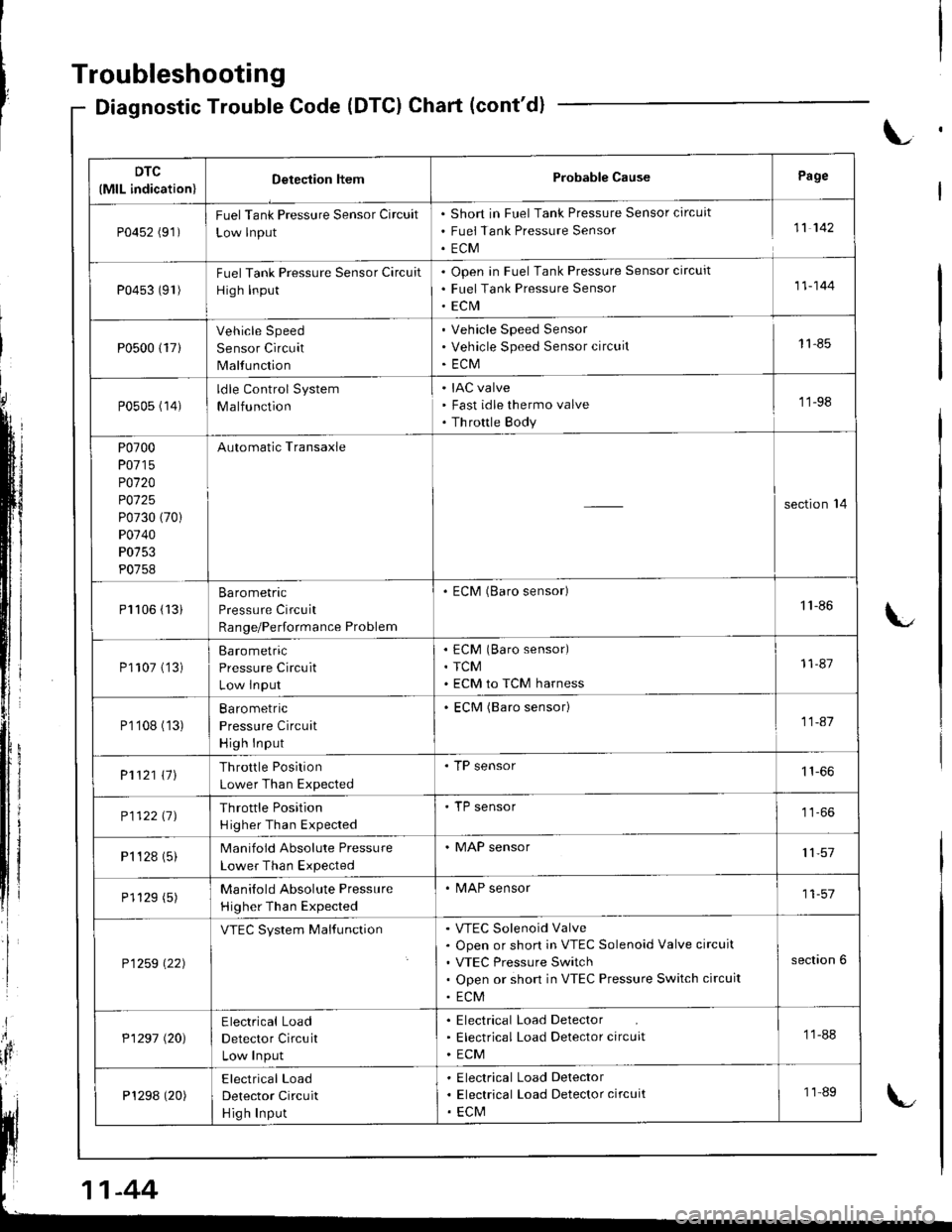
Diagnostic Trouble Code (DTCI Chart (cont'd)
L
DTC
(MlL indication)Detection ltemProbable CausePage
P0452 (91)FuelTank Pressure Sensor Circuit
Low lnput
Short in Fuel Tank Pressure Sensor circuit
Fuei Tank Pressure Sensor
ECM
11 142
P0453 (91)Fuel Tank Pressure Sensor Circuit
High Input
Open in Fuel Tank Pressure Sensor circuit
Fuel Tank Pressure Sensor
ECrVI
11-144
P0500 {17}
Vehicle Speed
Sensor Circuit
Malfunction
Vehicle Speed Sensor
Vehicle Speed Sensor circuit
ECM
11-85
P0505 (14)ldle Control System
Malfunction
IAC valve
Fast idle thermo valve
Th rottle Body
'11-98
P0700
P0715
P0120
P0125
P0730 (70)
P0740
P0753
P0758
Automatic Transaxle
section'14
Pl106 (13iBarometric
Pressure Circuit
Range/Performance Problem
. ECM (Baro sensor)1'l -86
P1107 ('�]3)Barometric
Pressure Circuit
Low lnput
ECM (Baro sensor)
TCM
ECM to TCM harness
11-87
P1'108 (13)Ba ro metric
Pressure Circuit
High Input
ECM (Baro sensor)11-41
P1121 \11Throttle Position
Lower Than Expected
. TP sensor
P112211JThrottle Position
H igher Than Expected
'TP sensor
P1 '�t 28 (5)Manifold Absolute Pressure
Lower Than Expected
. MAP sensor11,57
P1129 (5)Manilold Absolute Pressure
Higher Than Expected
. MAP sensor11-57
P1259 \22)
VTEC System MalfunctionVTEC Solenoid Valve
Open or short in VTEC Solenoid Valve circuit
VTEC Pressure Switch
Open or short in VTEC Pressure Switch circuit
ECM
section 6
P1297 (20)Electrical Load
Detector Circuit
Low Input
Electrical Load Detector
Electrical Load Detector circuit
ECM
11-88
P1298 (20)Electrical Load
Detector Circuit
Hig h Input
Electrical Load Delector
Electrical Load Detector circuit
ECM
11-89
-44
Page 268 of 1681

The scan tool indicates Diagnostic Trouble Code (DTC) P0122: A low voltage problem in the Throttle Position{TP) sensor circuil.
The TP Sensor is a potentiometer. lt is connected to the throttle valve shaft. As the throttle position changes, the throttleposition sensor varies the voltage signalto the ECM.
ARUSHHOI.DER
BRUSH 5
FULLTHROTTLE
TP SENSOR CONNECTOR IC115)
Wire side of temale terminals
ECM CONNECTOR D {16P)
(GRN/BLUI
Wire side ot female terminals
sG2 / -\
fr rrr r 'tr\
- 1 2 3)
|{- f- /
| _-,/tlI /6 I TPS-\j/
Terminalside of maletermrnats(To page 11-64)
The MIL has be€n reDort€d on.DTC P0122 is stor€d.
Problem veritication:1. Start the engine. Hold theengine at 3,000 rpm with noload (in Park or neutral) untilthe radiator fan comes on, thenturn the ignition switch OFF.2. Turn the ignition switch ON (ll).
3. Check the throttle positionwith the scan tool.
ls there approx. 10% whenthe throttle is fully closedand approx.90o/o when thethrottle is fully opened?
lntermittenl tailure, system is OKat this time. Check tor poor con-nections or loose wires at Cl15{TP s€nsor) end ECM.
Check lor an open in ihe wire(VCC2line):
1. Turn the ignition switch OFF.2. Disconnect the TP sensor con,nector,3. Turn the ignition switch ON (ll).4. Measure voltage betweenTP sensor connector terminalsNo. l and No. 3.
ls there approx. 5 V7
Check fo. an open in wire IVCC2line):lleasure voltage between ECMconnector terminals D10 and D11.
R.p.ir opon in tho wire betwoenECM {D101 and TP sen3or.ls there approx. 5 V?
Substitute a known-good ECMand recheck. lf pr6sc.ibed volt-age ia now available, replaco theoriginalECM.
Check for an open or 3hort in TP3ensor:1. Turn the ignition switch OFF.2. Measure resistance betweenTP sensor terminals No. '1 andNo.2 with the throttle fullyctoseo,
OUTPUT VOLTAGE {V)
4
RESISTOR3
2
TERMINAL
I
o
THROTTLEOPEI{INGBUS}IINGIDLE
sG2{GRN/BLK)vcc2IYEL/BLU}
vcc2{YEL/BI
l\e
4E
i2iRN,
. llLI5
6/101t 12
t515
(cont'd)
Page 303 of 1681

ldle Control System
ldle Control System
i P0505 | fne scan tool indicates Diagnostic Trouble Code (DTC) P0505: ldle control system malfunction,
NOTE: ll DTC Pl508 is stored at the same time as DTC P0505, troubleshoor DTC P1508 first. then troubleshoot DTC P0505.
Possible Cause
. IAC valve mechanical malfunctiorr
. Fast idle thermo valve malfunction (A"/T)
. Throttle body clogged port, improper adjustment
. Intake manifold, gasket leakage
. Intake air hose loose, leakage
a Vacuum hoses leakage
. ECT sensor incorrect output
. Throttle Position sensor incorrect output
Troubleshooting Flowchart
Problem verification:1. Start the engine. Hold theengine at 3,000 rpm wath noload 1in Park or neutral) untilthe radiator fan comes on,then let it idle.2. With the scan tool, check thefollowing items.- Throttle position should beapprox. 10% with the throttle fully closed.Engine coolant tempera-ture should be 116 212F(80 - 100'c).lf they are not within thespec., repair the faulty sensor crrcuft,3 Check the engine speed atidle with no-load conditions:headlights, blower fan, reardefogger, radiator fan, and airconditioner are not operating,
- The MIL has been reported on.- DTC P0505 is stored.
ls it 750 t 50 rpm (81881,
818C1 engines), 800 I 50 rpm(818C5 engine)?
Intermittent failur6, svstsm is OKat this tim€.
ls it 550 rpm (81881,818C1
engines), 600 rpm {818C5enginelor less?
-98
(To page 11'99)(To page 11-99)
Page 304 of 1681

Chock th6 IAC vrlv.:Disconnect the 2P connector tromthe IAC valve.
ooes lhe engine speed droporlhe engine stall?
Adiu3t th. lb.r.l idle Bp..d lrocplgc 11-1111.lf it's impo3.iblo, clo.n tho portsin thc throftlc body.
Ch.ck th€ frtt idl. th.rmo vrlv.:1, Turn the ignition switch OFF.2. Remov€ th6 intake air ductfrom the throttle body.3. Slart the engine and let it idle.4. Put your finger on the lowerport in the thronle bodv.
Chack angina coobnt Lv.l and fo.ai. in th. cooling ry.l.m. It OK,r.place tha fatt ldla lftarmo valva.Does the engine speed drop?
Put your linger on the uppor portin the throttle body.
Chacl tor vrcuum leek3, m.lcilJa th6 throttlo valvo ir com-plotaly cloaad, rnd ropair aa nac-a3aatY,
ooes ihe engin6 speed drop?
Adiutt th€ idl. .p..d l..r p.g.11-1111. lf it'. impo3riblo, rcpl.c.thc IAC v.lvc.
{A/T model)----tLOWERPORT
L. _. _._. _. _. _.-l
IDLETHERMOVALVE
1 1-99
Page 305 of 1681

ldle Control System
Problem verification:'1. Do the ECM Feset Procedure.2. Sta rt the engine.
ldle Air Control (lAG) Valve
The scan tool indicates Diagnostic Trouble Code (DTC) P1508: A problem in the ldle Air Control (lAC) valve
crrcurt.
The IAC Valve changes the amount of air bypassing the throttle body in response to a current signal from the Eclvl in
order to maintain the proper idle speed.FTom AIB To INTAKECLEANER MANIFOLD
IAC VALVE CONNECTOR IC116}
YES
WIRE SIDE OF FEMALE TERMINALS
ECM CONNECTOR A {32PI
Check for an open or short in thewire IIACV line):1. Turn the agnition switch OFFand reconnect the IAC valve
2. Disconnect the ECM connector A (32P).
3. Turn the ignition swatch ON (ll).
4. M easu re voltage betweenbody ground and ECM connector terminal A12.
IACV {8LK/BLU}
tacv{BLK/BI-UI
The MIL has been reoorted on.OTC Pl508 is stored.
lntermittent failure, svstem is OKat this time. Check for ooor con-nections or loose wires at C116{lAC valvel and ECM.
ls DTC P1508 indicated?
Check tor an open in lhe wirellGPl line):1. Turn the ignition switch OFF.2. Disconnect the IAC valve con
3. Turn the ignition switch ON (ll).
4. Measure voltage betlveen bodyground and the IACV connectorterminalNo.2.
Repair open in the wire betweenIAC valve and PGM-FI main relav-ls there battery voltage?
Repair open or shon in the wi.ebetween ECM {A12l and lAc valve.ls there battery voltage?
Check the IAC velve function:Momentarily connect ECM con-nector terminals A12 and A10with a jumper wire several times.
Does the IAC valve click?
Substitute a known-good ECMand rocheck. lf symptom/indica-tion goes away. replace the origi-nal ECM.
','*',,'Llu.9', I l112 15 16 17 1a1o20/
l--12u1 z"-if1za-2"' . '1 .
910
t-r '21
Wire side of female terminals
JUMPER WIRE
1-100