1998 HONDA INTEGRA sensor
[x] Cancel search: sensorPage 219 of 1681

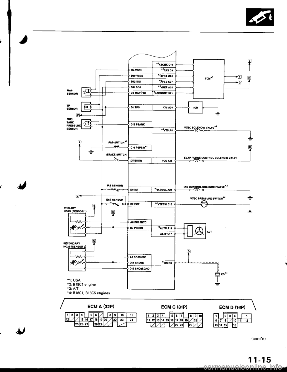
System DescriPtion
Electrical Connections
FUELIN'ECTOHS
EVAP COIiTIBOL CANISTEAvE|rISHUT VAIVE
sotENoto vaLvE
lo FAOIAIOB FAN FELAY,CONOEI{SEh FAN FELAY
FUSESr-1) BATTERY {100 A)*
€) INTERIOF LIGHT {7.5 A}.
€) HORN STOP 120 A)'
o rcl (,$ A)*
o BACK UP IRADIO) 17.5 A)*
@ Fr €/M t15 Al'.'I NO. .I3 FUEL PUMP ISRS UNIN (15 A)
a,J No. 25 METER 17.5 Al
O No. 15 ALTERNATOR SP SENSOR {7.5 A}(0 No. 17 HEATER A/C R€LAY (7.5 A)(i) No. 31 STAnTEB SIGNAL (7.5 A)
*: in the under'hood fuse/relaY box
Page 220 of 1681

SENSOF
sEitsoi
FUEITANKPFESSI'REgEl{soR
CO|IIFOL SOLENOID VAIVE
soLtltoto vlLvEt2
ytEc PREgsuiE Ewrc8*
s€col{oaFY
*1: USA*2:818C1 engine+3: A,/T*4: B18Cl, 818C5 engines
BFAK€ SWITCII
IATSENSOR
(cont'd)
11-15
Page 221 of 1681

t;
System Description
sG2
Electrical Connections (cont'd)
c223 CiOSi
I
PO2SHTC
vccl
vcc2
cnl6lu'
OFN/BLK
YEVWHT
WHT/YEL
REO/YEL
YEVBLU
RED/ALX
WHI/qFN
TPS
neo,wrtrJffil
oFN/Btx--1-:JECt SE SOR
neonerJf$l
cnvELx--L# |IAT SENSOR
vsveLu--JJr[5lneozgr.x--_l F--? |cnN/Blx 1-:JfP SENSOR
".,.""11--,"u-l
I WECSOLENOIDI VALVE
VTEC PIIESSUFEswtTcH
-+ BLU/BLK - |----o o--l I- +- aq'- --l # |
+ i crdl
fr i-'-
t'=- - -
l
*-,*{Fli
,.,__!i
CXFSEN90B
._.._.._..J
PAI||ARYHO2S (SENSOR 1)cfl4ft'-------------1YEVBED ---l f .g--t- IFEo/cBN ___l F=-< f Icnr,wxr"_ lFj IIIAP SENSOB
cill
*4: 818C1, 818C5 engines*5: 81881 engine
11-16
Page 226 of 1681
![HONDA INTEGRA 1998 4.G Workshop Manual _{-]
..*-l--1E____]:l
EFAXE SWITCH
taa,t"r-{YEVGR
----
YEL/8rx --]
IeLx,YrKI.--GRI,/ELU--- lYEVGR| ---
eu--------1
FUEL TANKPRE9SUNE SENSOR
c793
EVAP BYPASSSOLENOIOVALVE
. ,.tn"* jf ,.rn""YEVBLU HONDA INTEGRA 1998 4.G Workshop Manual _{-]
..*-l--1E____]:l
EFAXE SWITCH
taa,t"r-{YEVGR
----
YEL/8rx --]
IeLx,YrKI.--GRI,/ELU--- lYEVGR| ---
eu--------1
FUEL TANKPRE9SUNE SENSOR
c793
EVAP BYPASSSOLENOIOVALVE
. ,.tn"* jf ,.rn""YEVBLU](/manual-img/13/6069/w960_6069-225.png)
_{-]
..*-l--1E____]:l
EFAXE SWITCH
taa,t"r-{YEVGR
----
YEL/8rx --]
IeLx,'YrKI.--GRI,/ELU'--- lYEVGR| ---
eu--------1
FUEL TANKPRE9SUNE SENSOR
c793
EVAP BYPASSSOLENOIOVALVE
. ,.tn"* jf ,.rn""YEVBLU -l F YEV9LUr-r cnrf lI r-r cnlrt-GRN/BLX I f cRri,/ErxBLK/YEL I l Br.t<,/wrreru'� l| alrf-
Brx/,r'rrr lf Erx/wrr
11-21
Page 241 of 1681

Troubleshooting
Troubleshooting Procedures (cont'd)
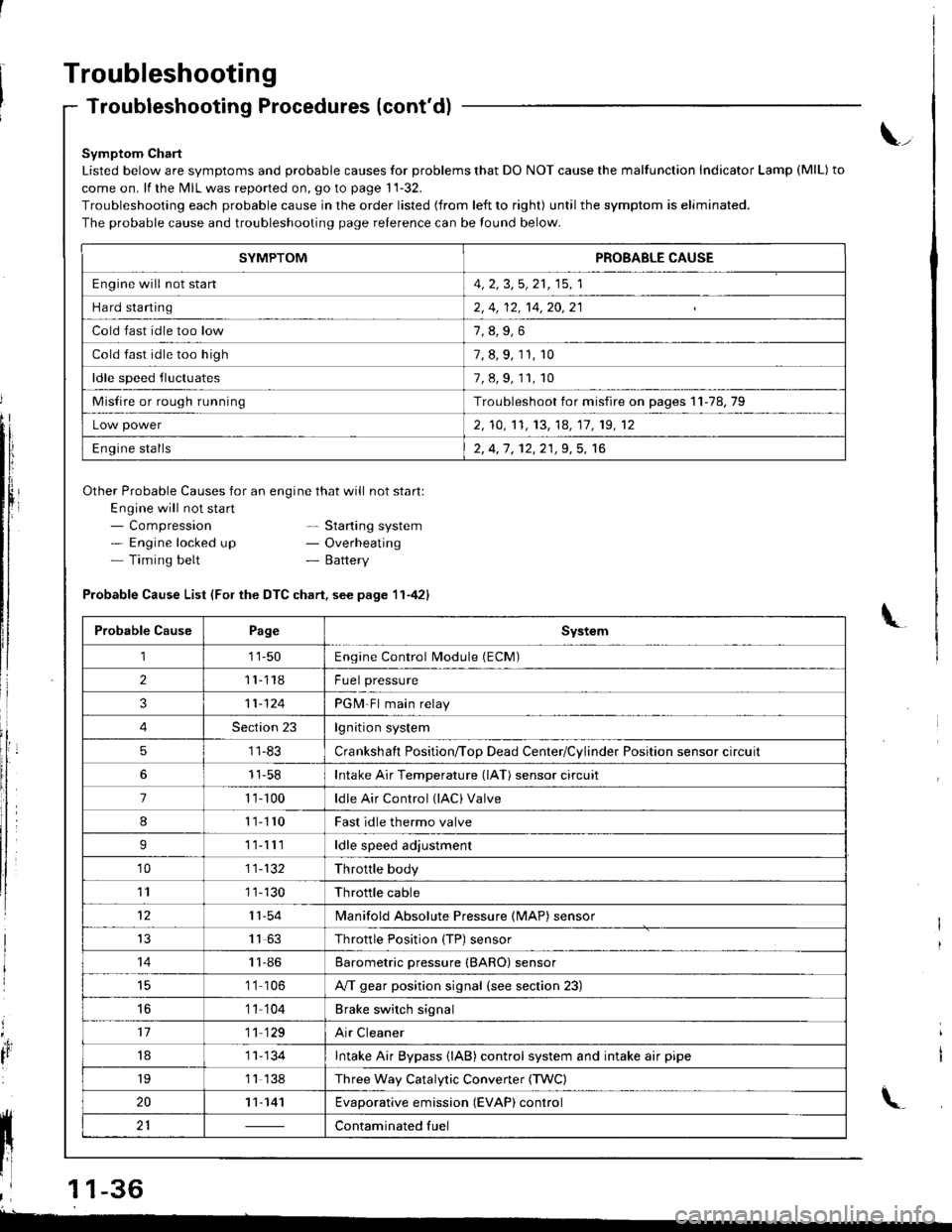
Symptom Chart
Listed below are symptoms and probable causes for problems that DO NOT cause the malfunction Indicator Lamp (MlL) to
come on. lf the MIL was reported on, go to page 11-32.
Troubleshooting each probable cause in the order listed (from left to right) until the symptom is eliminated.
The probable cause and troubleshooting page relerence can be found below.
Other Probable Causes for an engine that will not start:
Engine will not sta rt- Compression- Engine locked up- Timing belt
\_
- Starting system- Overheating- Battery
'4,
It
Probable Cause List (For the DTC chart. see page 11-421
Probable CausePageSystem
111-50Engine Control Module (ECM)
211118Fuel pressure
311-124PGM-Fl main relay
4Section 23lgnition system
51 1-83Crankshaft Position/ToD Dead Center/Cylinder Position sensor circuit
11-58Intake Air Temperature (lAT) sensor circuit
71 '�t- 100ldle Air Control (lAC) Valve
811110Fast idle thermo valve
I11lllldle speed adjustment
'1011-132Throttle body
111 1-130Throttle cable
1211-54lvlanifold Absolute Pressure {MAP) sensor
IJ1163Throttle Position {TP) sensor
1411-86Barometric pressure (BARO) sensor
1 '1 106A/T gear position signal {see section 23)
16'1 1 104Brake switch signal
1711 129Air Cleaner
181 1- 134Intake Air Bypass {lAB} control system and intake air pipe
19'1 1 138Three Way Catalytic Convener (TWC)
2011-141Evaporative emission (EVAP) control
21Contaminated fuelll ll 21 | - | cont"-in"t"o tu"
11 l-
I
,l 11-36
-
SYMPTOMPROBABLE CAUSE
Engine will not stan4, 2, 3,5, 21, 15, 1
Hard starting2, 4, 12, 14,20,21
Cold fast idle too low
Cold fast idle too high7, 8, 9, 11, r0
ldle speed fluctuates7,8,9,11,10
Misfire or rough runningTroubleshoot for misfire on pages 11-78,79
Low power2, 10,'t1, 13, 14, 17, 19, 12
Engine stalls2, 4,1 , 12,21,9, 5, 16
Page 242 of 1681

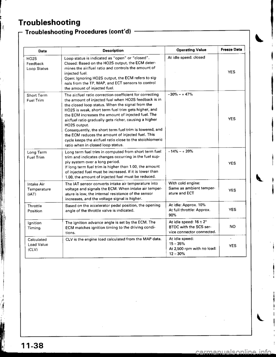
ECM Data
By connecting the OBD ll scan tool or the Honda PGM Tester to the 16P data link connector (DLC), various data can beretrieved from the EcM The items risted in the tabre berow conform to the sAE recommended practice.The Honda PGM Tester also reads data beyond that recommended bv SAE.understanding this data wirl herp to rind the causes of intermiftent fairures or engine probrems.
NOTE:
' The "operatlng values" given below are approximate values and may be different depending on the environment andthe individual car.' Unless noted otherwise, "at idle speed" means idling with the engiFe completely warmed up, transmissron in park orneutral and the A,/C and all accessories turned off.
DataDescriptionOperating ValueFreeze Data
Diagnostic
Trouble Code(DTC)
lf the ECM detects a problem, it will store tt as a cocteconsisting ot one letter and four numbers.Depending on the problem, an SAE-defined code{Poxxx) or a Honda-defined code (plxxx) will beoutput to the lester.
lf no problem is detected,
there is no output.
YES
Engine SpeedThe ECM computes engine speed from the signalssent from the Crankshaft Position sensor.This data is used for determining the I|me andamount of fuel injection.
Nearly the same as
tachometer indication at
idle speed:
81881,818C1 engines:
750 t 50 rpm
818C5 engine:
800 1 50 rpm
YES
Vehicle SpeedThe ECM converts pulse signals trom the VehicleSpeed Sensor (VSS) into speed data.
Nearly the same as
speedometer indicationYES
Manitold
Absolute
Pressure {MAP)
The absolute pressure created in the intake manifoldby engine load and speed.With engine stopped:
Nearly the same as atmo
spheric pressure. At idle
speed:
24 - 37 kPa (180 - 280
mmHg,7.1 1'1.0 inHg)
YES
Engine Coolant
Temperature
(ECT)
The ECT sensor converts coolant temperature intovoltage and signals the ECM. The sensor is a thermis-tor whose internal resistance changes with coolanttemperature. The ECM uses the voltage signals fromlhe ECT sensor to determine the amount of iniectedfuel.
With cold engine:
Same as ambient temper
ature and IAT
With engine warmed up:
approx. 176 - 200'F
{80 - 93.C)
, YES
Heated Oxygen
Sensor (HO2S)
{sensor 1)(sensor 2)
The Heated Oxygen Sensor detects the oxygen con-tent in the exhaust gas and sends voltage signals tothe ECM. Based on these signals,lhe ECM controlsthe airlfuel ratio. When the oxygen content is high{that is, when the ratio is leaner than the stoichiomericratio), the voltage signal is lower. When the oxygencontent is low (that is, when the ratio is richer thanthe stoichiomeric ratio), the voltage signal is higher.
0.0 - 1.25 V
At idle speed:
abour 0.'1 - 0.9 V(sensor I )NO(sensor 1)
(conl'd)
11-37
Page 243 of 1681

Troubleshooting
DataDescriotionOperating ValueFreeze Data
HO25
Feedback
Loop Status
Loop status is indicated as "open" or "closed".
Closed: Based on the H02S output, the ECM deter-
mines the airlfuel ratio and controis the amount of
iniected fuel.
Open: lgnoring HO2S output, the ECM refers to sig-
nals from the TP, MAP, and ECT sensors to control
the amount of iniected fuel.
Al idle speed: closed
YES
Short Term
Fuel Trim
The airlfuel ratio correclion coeificient lor correcting
the amount ol iniected fuel when HO2S feedback is in
the closed loop status. When the signal from the
HO2S is weak, short term fuel trim gets highef. and
the ECM increases the amount of injected fuel The
airlfuel ratio gradually gets richer, causing a higher
HO2S output.
Consequentlv, the short term fuel trim is lowered, and
the ECM reduces the amount of injected tuel. This
cycle keeps the airlfuel ratio close to the stoichiomeric
ratio when in closed loop status.
-30o/" - + 41%
YES
Term
Trim
Long
F uel
Long term fuel trim in computed trom short term fuel
trim and indicates changes occurring in the fuel sup-
ply system over a long period.
lf long term fuel trim is higher than 1.00, the amou nt
of injected fuel must be increased. ll it is lower than
1.00, the amount of iniected fuel must be reduced
-14% - + 2Oo/"
YES
lntake Air
Temperature(rAT)
The IAT sensor converts intake air temperature into
voltage and signals the ECM. When intake air temper-
ature is low, the internal resistance of the sensor
increases, and the voltage signal is higher.
With cold engine:
Same as ambient temPer-
ature and ECTYES
Throttle
Position
Based on the accelerator pedal position. the opening
anole of the throttle valve is indicated.
Ar idle: Approx. 107o
At full throttle: Approx.
90%
YES
lgnition
Timing
The ignition advance angle is set by the ECM. The
EClvl matches ignition timing to the driving condi-
tio ns.
At idle speed: 16 t 2'
BTDC with the SCS ser-
vice connector connected.
NO
Calculated
Load Value
(CLV)
CLV is the engine load calculated from the MAP data.At idle speedi
15 - 35%
At 2,500 rpm with no load:
12 - 30./.
YES
-38
Page 244 of 1681

Engine Control Module Terminal Arrangement
ECM CONNECTOR A I32P}
ECM CONNECTOR A I32PI
*1: USA*2:818C1 engine*3:A,/T*4: 818C1, 818C5 engines
female terminals
NOTEr Standard battery voltageis 12 V.
{cont'di
LG22A
TerminalWireTerminal nameDescriptionSignal
YELlNJ4 (No. 4 FUEL INJECTOR)Drives No. 4 fuel iniector.With engine running: pulses2BLUlNJ3 (No.3 FUEL INJECTOR)Drives No. 3 fuel injector.
3REDlNJ2 (No.2 FUEL INJECTOB)Drives No.2 fuel injector.
BRNlNJl (No. 1 FUEL INJECTOR)Drives No. l Iuel iniector.
5GRN/REDS 02SHTC (SECONDARY
HEATED OXYGEN SENSORHEATER CONTROL)
Drives secondary heated oxygensensor heater,With ignition switch ON (ll)i battery volrageWith fully warmed up engine runningiduty controlled
6ORN/BLKP O2SHTC {PRIMARY HEAIEDOXYGEN SENSOB HEAIERCONTFOL)
Draves primary heated oxygensensor heater,With ignition swirch ON (ll): battery voltageWith lully warmed up engine running:duty controlled
84G RNI/ELVTS (VTEC
SOLENOID VALVE)Drives VTEC solenoid valve.With engine at low rpm: 0 VWith engine at high rpm: battery voltageIBRN/BLKLG1 (LOGIC GROUND)Ground for the ECM control circuit.Less than 1.0 V at alltimes10BLKPGl (POWER GROUND)Ground for the EC[, power circuit.Less than 1.0 V at all times't'lYEUBLKIGPl {POWER SOURCE)Power source for the ECMcontrolcircuit.With ignition switch ON 1ll): battery voltageWith ignition switch OFF| 0 V
12BLI(8LUIACV(IDLE AIR CONTROL VALVE}Drives IACV.With engine running: about 6 V 10 V(depending on engine speed)
REDPCS (EVAP PURGE CONTROLSOLENOID VALVE)Drives EVAP purge controlsolenoid valve.Wilh engane running, engine coolant above154"F (68'C): duty controlled
GRN/BLUFLR (FUEL PUMP RELAY)Drives fuel pump relay.0 V for two seconds after turning ignitionswitch ON (ll), then battery voltage
17B LVBEDACC (fuC CLUTCH RELAY)Drives A,/C clulch relay.With compressor ON: 0 VWith compressor OFFt baftery voltage
18GRN/ORNMIL (I\4ALFUNCTION
INDICATOR LAMPiDrives MlL.With MIL turned ON:0 VWjth MIL turned OFF: battery vottage
19*,WHT/GRNALTC (ALTERNATOR
CONTROL)Sends alternator control signal,With fully warmed up engine runninglbattery voltageDuring driving with small electrical load: 0 V
20YEUGRNICM (IGNITION CONTROLMODULE)Sends ignition pulse.With ignition switch ON (ll): battery voltageWith engine running: about'10 V(depending on engine speed)22BRN/BLKLG2 (LOGIC GROUND)Ground forthe ECM controlcifcuit.Less than 1.0 V at all times8LKPG2 (POWEfl GROUND)Ground for the ECM power circuit.Less than 1.0 V at all times
24YEUELKIGP2 (POWER SOURCE)Power source for the ECMcontrolcircuit,With ignition switch ON {lli: battery voltageWith ignition switch OFF: 0 V
25*3WHT/BLKVREF (REFERENCE VOLTAGE)Provides reference voltage toother control units,With ignition swirch ON (ll): about 5 VWath ignition switch OFF: 0 V
26. 'PNK/8LU
IAB SOL (INTAKE AIR BYPASSCONTROL SOLENOID VALVE)Drives IAB conlrol solenoidWith engrne running, engrae speed betow5,750 rpm: battery voltageWith engine running, engine speed above5,750 rpm: 0 V
27* IGRNFANC (BADIATOR FANCONTROL)Drives radiator fan relay.With radiator {an running: 0 VWith radiator Ian stopped: battery voltage
2ABLU2WBS (EVAP BYPASSSOLENOID VALVE)Drives EVAP bypass solenoidWith ignition switch ON (ll): battery vottage
29LT GRNVSV (EVAP CONlROLCANISTER VENT SHUT VAVLE)Drives EVAP control canister ventshut valve.Wilh ignilion switch ON lll): banery votrasc
1 1-39