1998 HONDA INTEGRA sensor
[x] Cancel search: sensorPage 245 of 1681

I
t
h,,l,!
il
Troubleshooting
ECM CONNECTOR {31P)
Engine Control Module Terminal Arrangement (cont'd)
ECM CONNECTOR C {31P)
235srsscs1112t31515t71A19
2A
Wire side of lemale terminals
NOTE: Standard battery voltage is 12 V.
TerminalnumbercolorTerminal namoD6scriptionSignal
1BLU/REDCKF P (CKF SENSOR P SIDE)Detects CKF sensor.With engine running: pulses
28LUCKP P (CKP SENSOR P SIDE)Detects CKP sensor.With engine running: pulses
3GRNTDC P {TDC SENSOR P SIDE)Detects TDC sensor,With engine running: pulses
YELCYP P (CYP SENSOR P SIDE)Detects CYP sensor,With engine running: pulses
5BLU/REDACS (AJC SWITCH SIGNAL)Detects A,/C switch signal.With A,/C switch ON: 0 VWith A,/C switch OFF: battery voltage
6BLUA/VHTSTS (STARTEB SWITCHSIGNAL)
Detects starter switch signal.With staner switch ON: battery voltageWith starter switch OFF: 0 V
7BRN,AiVHTSCS (SERVICE CHECKSIGNAL)Detects service check connectorsignal (the signalcausing a DTC;ndication).
With the co n nector con nected: 0 VWath the connector disconnected: about 5 V
8GRNAVHTK LINESends and receives OBD ll scantool and PGM tester signal.With ignition switch ON (ll): about 5 V
9YELFAS lFEEDBACK AT SIGNAL)Sends feedback signal for theTCM,At idle: about 5 VDuring shifting: momenlary change to 0 V
10WHT/BLU
VBU (VOLTAGE BACK UP)Power source for the ECMcontrolcircuit,Power source for the DTC
Battery voltage at all times
t1WHT/REDCKF M (CKF SENSOR I\4 SIDE)Ground for CKF sensor.
12BLUI/E LCKP M (CKP SENSOR M SIDE)Ground for CKP sensor.
WHT/BLUTDCM (TDC SENSOR M SIDE)Ground tor TDC sensor.
14CYPM (CYP SENSOR M SIDE)Ground for CYP sensor.
15*.BLU/BLKVTP SW (VTEC
PRESSUFE SWITCH)Detects VTEC pressure switchsr9nal.
With engine at low rpm:0 VWith engine at high rpmlbattery voltaqe
161,GRN
PSPSW (P/S OILPRESSURE SWITCH)Derecls PSP switch signal.At idle with steering wheel in straight aheadpositioni 0 VAt idle with steering wheelat full lock: batteryvoltage
17WHT/REDALTF (ALTERNATOR FRSIGNAL)Detects alternator FR signal.With fully warmed up engine running:0 V battery voltage (depending onelectrical load)
18ORNVSS (VEHICLE SPEEDSENSORiDetects VSS signal.With ignition switch ON (ll) and lrontwheels rotating: cycles 0 V- 5 V
19*3BLUAT CHK (A/T FI DATA LINE)Detects TCM data signal.With ignition switch ON (ll)i pulses
21*LT GRNBARO OUT (SAROMETRIC
SENSOR OUTPUT S!GNAL)Sends barometric sensor outputsrgnal,With ignition switch ON (ll): about 3 V(depending on barometric pressure)
27 x3GRYAFSB (A"/T FI SIGNAL B)Detects retard signal from theTCM,At idle: about 5 VDuring shifting: momentary changeto0V
28+1GRN/8LUA+SA (A/T FI SIGNAL A)Detects retard signal from theTCM.At idle: about 5 VDuring shifting: momentarV changeto0V
29+3LT GRN/BLKATPPN (A/T GEARPOSITION SWITCH)Detects A,/T gear position switchsrgnal-In E orE positionr 0VIn anv other position: battery voltage
*1: USA*2:818C1 engine*3: A/T*4: 818C1, 818C5 engines
Page 246 of 1681

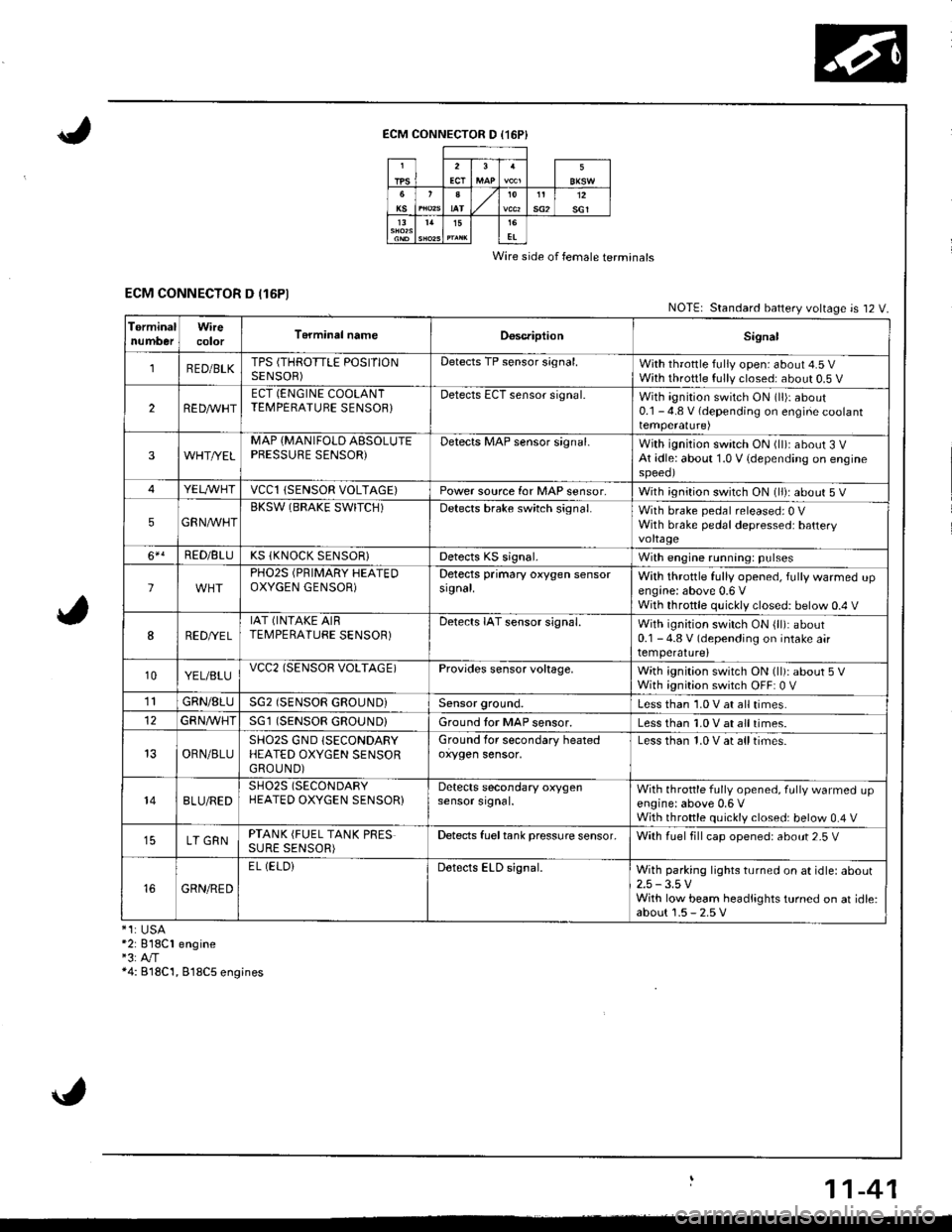
ECM CONNECTOR D (16P}
Wire side of female terminals
ECM CONNECTOR D (16P1NOTE| Standard battery voltage is 12 V.
TerminalnumberWirecolorT6rminal nameDoscriptionSignal
1RED/BLKTPS (THROTTLE POSITIONSENSOR)Detects TP sensor s;gnal.With throttle fully open: about 4.5 VWith throttle fully closed: about 0.5 V
2REDAr'r'HTECT (ENGINE COOLANTTEMPERATUBE SENSOB}Detects ECT sensor signal.With ignition switch ON (ll)r about0.1 - 4.8 V (depending on engine coolanttemperalure)
3WHT//ELMAP {MANIFOLD AESOLUTEPBESSURE SENSOR)Detects MAP sensor signal.With ignition switch ON (ll)iabout 3 VAt idle: about 1.0 V {depending on enginespeeol
4YELA/VHTvccl{SENSOR VOLTAGE)Power source for MAP sensor,With ignition switch ON (ll): about 5 V
5GRNAVHTBKSW (BRAKE SWITCH)Detects brake switch signal.With brake pedal released: 0 VWith brake pedal depressed: batteryvoltage
6*!RED/BLUKS (KNOCK SENSOR}Detects KS signal.With engine running: pulses
lPHO2S (PRIMARY HEATEDOXYGEN GENSOR)Detects primary oxygen sensorsignal.With throttle fully opened, fully warmed upengine: above 0.6 VWith throttle quickly closed: below 0.4 V
8RED/VEL
IAT (INTAKE AIRTEMPERATURE SENSOR)Detects IAT sensor signal.With ignition switch ON {ll): about0.1 - 4.8 V (depending on intake airtemperature)
10YEL/BLUvcc2(SENSOB VOLTAGE)Provides sensor voltage,With ignition switch ON (ll): about 5 VWith ignition switch OFF: 0 V
1lGRN/8LUSG2 (SENSOR GROUND}Sensor ground.Less than 1.0 V at all times.
GFNA/VHT(SENSOR GROUND}Ground tor MAP sensor.Less than 1.0 V at all times.
OBN/BLUSHO2S GND (SECONDARY
HEATED OXYGEN SENSORGROUND)
Ground for secondary heatedoxygen sensor,Less than 1.0 V at alltimes.
148LU/REDSH02S (SECONDARY
HEATED OXYGEN SENSOR}Detects secondary oxygensensor srgnal.With throttle fully opened. fully warmed upengine: above 0,6 VWith throttle quickly closed: below 0.4 V
LT GRNPTANK (FUEL TANK PRESSURE SENSOR)Detects fueltank pressure sensor.With luel fill cap opened: about 2-5 V
GRN/RED
EL (ELOiDetects ELD signal.With parking lights turned on at idle: about2.5 -3.5 VWith low beam headlights turned on at idle:about 1.5 - 2.5 V*1:USA*2: 818C1 engine"3:A"/T*4: B18C'1, 818C5 engines
11-41
Page 247 of 1681

1l
Troubleshooting
Diagnostic Trouble Gode (DTCI Chart
*: These DTCS will be indicated by the blinking ot the lvalfunction Indicator Lamp (MlL) with the SCS service connector
connected.
Ia
\
\
il
\
DTC
lMlL indication*lDetection ltemProbabls CausePage
P0107 (3)
Manifold Absolute
Pressure Circuit
Low Input
Open or short in MAP sensor circuit
MAP sensor
ECM
'11-54
P0108 (31
Manifold Absolute
Pressure Circuit
High Input
Open in MAP sensor circuit
MAP sensor
ECM
tt-5t,
P0112 (10)
Intake Air
Temperature Circuit
Low Input
Short in IAT sensor circuit
IAT sensor
ECM
11.58
P0113 {10)
lntake Air
Temperature Circuit
High Input
Open in IAT sensor circuit
IAT sensor
ECM
1'�1-59
P0116 (86)
Engine Coolant
Temperature Circuit
Range/Performance Problem
. ECT sensor' Cooling system11-60
P0117 (6)
Engine Coolant
Temperature Circuit
Low Input
Short in ECT sensor circuit
ECT sensor
ECM
1 '�t-61
P0118 {6)
Engine Coolant
Temperature Circuit
High Input
Open in ECT sensor circuit
ECT sensor
ECt\,4
1't -62
P0122l7l
Throttle Position
Circuit
Low Input
Open or shon in TP sensor circuit
TP sensor
ECM
11,63
P0123 (7)
Throttle Position
Circuit
High Input
Open in TP sensor circuit
TP sensor
ECM
I t-oc
P0131 (1 )
Primary Heated Oxygen Sensor
Circuit Low Voltage (Sensor 1)
Shon in Primary HO2S (Sensor'l) circuit
Primary H02S {Sensor 1)
Fuel supply system
ECM
11-67
P0132 (1)Primary Heated Oxygen Sensor
Circuit High Voitage (Sensor 1)
Open in Primary HO2S (Sensor 1) circuit
Primary HO2S (Sensor 1)
ECM
11-69
P0133 (61)Primary Heated Oxygen Sensor
Slow Response (Sensor 1)
. Primary HO2S (Sensor 1). Exhaust system1 1-70
,r:' 11-42
L
Page 248 of 1681

DTC(MlL indicationlDeteciion ltemProbable CausoPage
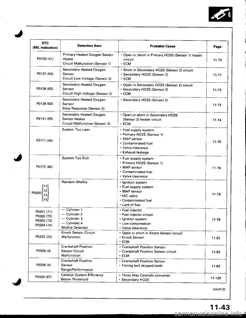
P013s {41)
Primary Heated Oxygen Sensor
Heater
Circuit Malfunction {Sensor '1)
. Open or shon in Primary HO2S (Sensor 1) heater
circuit. ECM1't-74
P0137 (63)Secondary Heated Oxygen
Sensor
Circuit Low Voltage (Sensor 2)
Short in Secondary HO2S (Sensor 2) circuit
Secondary H02S {Sensor 2)
ECM11-7'l
P0138 {63)
Secondary Heated Oxygen
Sensor
Circuit High Voltage (Sensor 2)
Open in Secondary HO2S (Sensor 2) circuit
Secondary HO2S (Sensor 2)
ECM
P0139 (63)Secondary Heated Oxygen
Sensor
Slow Response (Sensor 2)
Secondary HO2S (Sensor 2)
P0141 (651Secondary Heated Oxygen
Sensor Heater
Circuit Malfunction (Sensor 2)
. Open or short in Secondary HO2S(Sensor 2) heater circuit. ECM11-'14
P0171 (45)
System Too LeanFuel supply system
Primary HO2S {Sensor I )MAP sensor
Contaminated fuel
Valve clearance
Exhaust leakage
11-76
P0172 t45l
System Too RichFuel supply system
Primary HO2S (Sensor 1)
MAP sensor
Contaminated fuel
Valve clearance
11.76
,...,{iil
174l
Random Misfirelgnition system
Fuel supply system
MAP sensor
IAC valve
Contaminated fuel
Lack offuel
't 1-78
P0301 (71)
P03Q2 l'121
P0303 (73)
P0304 (74)
- Cylinder 1- Cylinder 2- Cylinder 3- Cylinder 4
Misfire Detected
Fuel injector
Fuel injector circuit
lgnition system
Low compression
Valve clearance
11-79
P0325 {23)
Knock Sensor Circuit
MalfunctionOpen or short in Knock Sensor circuit
Knock Sensor
ECM11-82
P0335 (4)Crankshaft Position
Sensor Circuit
Malfunction
Crankshaft Position Sensor
Crankshaft Position Sensor circuit
ECM1 1-83
P0336 (4)Crankshaft Position
Sensor
Range/Performance
. Crankshaft Position Sensor. Timing belt skipped teethIl-83
P0420 (67)Catalyst System Efficiency
Below Threshold
. Three Way Catalytic converter. Secondary HO2S11-139
(cont'd)
11-43
Page 249 of 1681

Troubleshooting
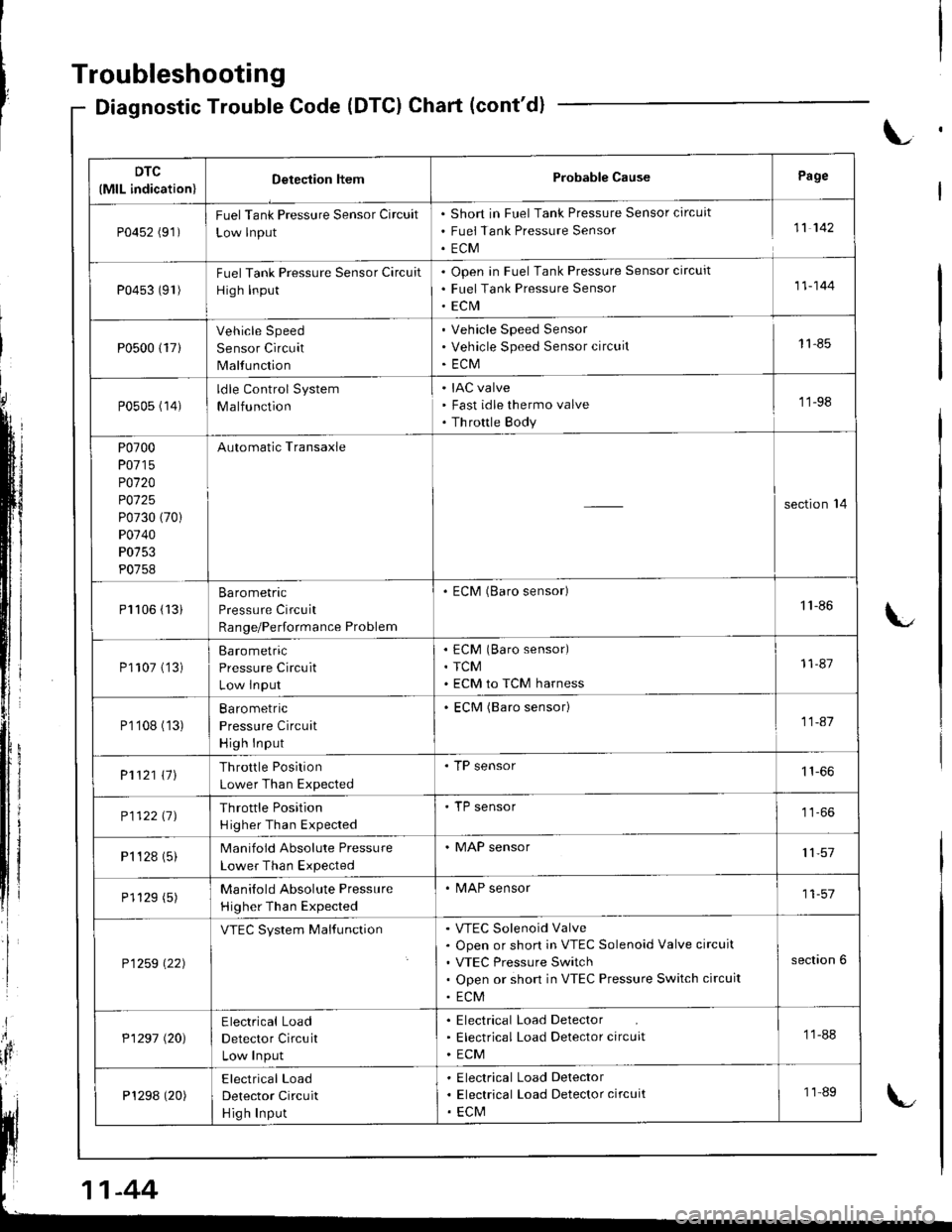
Diagnostic Trouble Code (DTCI Chart (cont'd)
L
DTC
(MlL indication)Detection ltemProbable CausePage
P0452 (91)FuelTank Pressure Sensor Circuit
Low lnput
Short in Fuel Tank Pressure Sensor circuit
Fuei Tank Pressure Sensor
ECM
11 142
P0453 (91)Fuel Tank Pressure Sensor Circuit
High Input
Open in Fuel Tank Pressure Sensor circuit
Fuel Tank Pressure Sensor
ECrVI
11-144
P0500 {17}
Vehicle Speed
Sensor Circuit
Malfunction
Vehicle Speed Sensor
Vehicle Speed Sensor circuit
ECM
11-85
P0505 (14)ldle Control System
Malfunction
IAC valve
Fast idle thermo valve
Th rottle Body
'11-98
P0700
P0715
P0120
P0125
P0730 (70)
P0740
P0753
P0758
Automatic Transaxle
section'14
Pl106 (13iBarometric
Pressure Circuit
Range/Performance Problem
. ECM (Baro sensor)1'l -86
P1107 ('�]3)Barometric
Pressure Circuit
Low lnput
ECM (Baro sensor)
TCM
ECM to TCM harness
11-87
P1'108 (13)Ba ro metric
Pressure Circuit
High Input
ECM (Baro sensor)11-41
P1121 \11Throttle Position
Lower Than Expected
. TP sensor
P112211JThrottle Position
H igher Than Expected
'TP sensor
P1 '�t 28 (5)Manifold Absolute Pressure
Lower Than Expected
. MAP sensor11,57
P1129 (5)Manilold Absolute Pressure
Higher Than Expected
. MAP sensor11-57
P1259 \22)
VTEC System MalfunctionVTEC Solenoid Valve
Open or short in VTEC Solenoid Valve circuit
VTEC Pressure Switch
Open or short in VTEC Pressure Switch circuit
ECM
section 6
P1297 (20)Electrical Load
Detector Circuit
Low Input
Electrical Load Detector
Electrical Load Detector circuit
ECM
11-88
P1298 (20)Electrical Load
Detector Circuit
Hig h Input
Electrical Load Delector
Electrical Load Detector circuit
ECM
11-89
-44
Page 250 of 1681

DTC(MlL indication)Dstection ll€mProbable CausePage
P1336 (54)Crankshaft Speed
Fluctuation Sensor
Intermittent lnterruption
. CKF sensor
1190
Pl337 (54)Crankshaft Speed
Fluctualion Sensor
No Signal
CKF sensor
CKF sensor circuit
ECM
'11-90
P't359 (8)
Crankshaft Position/Top
Dead Center/Cylinder Position
Sensor
Connector Disconnection
CKP/TDC/CYP sensor circuit
1't -92
P1361 (8)Top Dead Center
Sensor Intermittent
Interruptaon
. TDC sensor't1-83
P1352 (8)Top Dead Center
Sensor No Signal
TDC sensor
TDC sensor circuit
ECM
1183
P1381 {9}Cylinder Position Sensor
Intermittent Interruption
. CYP sensor11-83
Pl382 (9)Cylinder Position Sensor
No Signal
CYP sensor
CYP sensor circuit
ECM
11-83
P1456*6 (90)
Evaporative Emission Control
System Leak Detected (Fuel
Tank Area)
Fuel fill cap
Vacuum connection
Fueltank
Fuel tank pressure sensor
EVAP bypass solenoid valve
EVAP two way valve
EVAP control canister vent shut valve
EVAP control canister
EVAP purge control solenoid valve
11-146
P14s7*5 {90)
Evaporative Emission Control
System Leak Detected (EVAP
Control Canister Area)
Vacuum connection
EVAP control canister
Fuel tank pressure sensor
EVAP bypass solenoid valve
EVAP two way valve
EVAP control canister vent shut valve
FuelTank
EVAP purge control solenoid valve
'1 'l - 146
P1508 ( 14)
ldle Air Control Valve
Circuit Failure
IAC valve
IAC valve circuit
ECM
1 1-100
P1607 (-)Engine Control
Module Internal
Circuit Failure
. ECM
11-92
(cont'd)
11-45
Page 253 of 1681

PGM-FI System
System Description
ENGINE CONTROL MODULE (ECM)OUTPUTS
*1: USA*2: 818C1 engine*3: A,/T*4: 818C1, 818C5 engines
PGM-FI Sy3tem
The PGM-Fl system on this model is a sequential multiport fuel injection system.
Fuel lniector Timing and Duration
The ECM contains memories for the basic discharge durations at various engine speeds and manifold pressures. The
basic discharge duration, after being read out from the memory. is further modified by signals sent from various sensors
to obtain the final discharge duration.
ldle Air Control
ldle Ai. Control Valve (lAC Valve)
When the engine is cold, the Ay'C compressor is on. the transmission is in gear (Ay'T only)the brake pedal is depressed, the
P/S load is high, or the alternator is charging, the ECM controls current to the IAC Valve to maintain correct idle speed.
lgnition Timing Control
. The ECM contains memories for basic ignition timing atvarious engine speeds and manifold pressures, lgnitiontiming
is also adjusted for engine coolant temperature.
. AKnockControl System isadoptedwhich sets the ideal ignition timing for the octane n um ber of gasoline used*r,
Other Control Functions
L Starting Control
When the engine is started, the ECM provides a rich mi{ure by increasing fuel injector duration.
2. Fuel PumD Control
. When the ignition switch is initially turned on, the ECM supplies ground to the PGM-FI main relay that supplies
current to the fuel pump for two seconds to pressurize the fuel system.
. When the engine is running, the ECM supplies ground to the PGM-FI main relay that supplies current to the fuel
DUmO.
. When the engine is not running and the ignition is on. the ECM cuts ground to the PGM-FI main relay which cuts
current to the fuel oumo.
INPUTS
TDc/CKP/CYP Sensor
CKF Sensor
MAP Sensor
ECT Sensor
IAT Sensor
TP Sensor
HO2S
VSS
BARO Sensor
ELD*1
Starter Signal
ALT FR Signal
Air Conditioning Signal
A,/T Gear Position Signal*3
Battery Voltage (lGN.1)
Brake Switch Signal
PSP Switch Signal*'�
Knock Sensor*1
VTEC Pressure Switch*4
Fuel Tank Prssure Sensor
Fuel InjectorTiming and Duration
Electronic ldle Control
Other Control Functions
lgnition Timing Control
ECM Back-uD Functions
Fuel-lnjectors
PGM-Fl Main Relay (Fuel Pump)
MIL
IAC Valve
A,/C Compressor Clutch Relay
Radiator Fan Belay*1
Condenser Fan Relay
ALT*1
rcM
EVAP Purge Control Solenoid
Valve
H02S Heater
VTEC Solenoid Valve*'
IAB Control Solenoid Valve*,
EVAP Bypass Solenoid Valve
EVAP Control Canister Vent
Shut Valve
11-48
Page 254 of 1681

3.Fuel Cut-off Control
. Du ring dece leration with the th rottle va lve closed, cu rrent to the fuel injectors is cutoffto improvefuel economyat
speeds over following rpm:. B'1881 engine: 970 rpm {Canada model: 1.050 rpm). B18C1 engine:970 rpm {Canada model: 1.050 rpm). 818C5 engine: 1,300 rpm (Canada model: 1,400 rpm)
. Fuel cut-off action also takes place when engine speed exceeds 7,000 rpm (B'1881 engine), 8.100 rpm (818C1
engine) or 8,600 rpm (818C5 engine), regardless ol the position of the thronle valve, to protect the engine from
over-revving.
A,,/C ComDressor Clutch Relav
When the ECM receives a demand for cooling from the air conditioning system, it delays the compressor from being
energized, and enriches the mixture to assure smooth transition to the A,/C mode.
Evaporative Emission (EVAP) Purge Control Solenoid Valve
When the engine coolanl temperature is above '154'F (68'C) and the air conditioner on. the ECM controls the EVAPpurge control solenoid valve which controls vacuum to the EVAP purge control canister.
Intake Air Eypass (lAB) Control Solenoid Valve*a
When the engine rpm is below 5,750 rpm, rhe IAB control solenoid valve is activated by a signal from the ECM, intake
air flows through the long intake path, then high torque is delivered. At speeds higher than 5,750 rpm, the solenoidvalve is deactivated by the ECM, and intake air flows through the short intake path in order to reduce the resistance in
airflow.
Sell-diagnosis Function lMalfunction Indicator Lamp {MlL)lWhen an abnormality occurs in a signal from a sensor, the ECM supplies ground for the MIL and stores the code in
erasable memory. When the ignition is initially turned on, the ECM supplies ground for the N4lL tor two seconds to
check the MIL bulb condition.
Two Driving Cycle Detection Method
To prevent false indications, the Two Driving Cycle Detection Method is used for the HO2S, fuel metering-related, idle
control system, ECT sensor, TWC and EVAP control system and other self-diagnostic functions, When an abnormality
occurs, the ECM stores it in its memory. When the same abnormality recurs after the ignition switch is turned OFFand ON (ll)again, the ECM informs the driver by lighting the MlL.
However, to ease troubleshooting, this function is cancelled when you shon the service check connector. The MIL will
then blink immediately when an abnormality occurs.
4.
5.
6.
3.
4.
ECM Fail-safe/8ack.up F0nctions
1. Fail-sate Function
When an abnormality occurs in a signal from a sensor, the ECM ignores that signal and assumes a pre-programmed
value for that sensor that allows the enqine to continue to run.
2. Back-uo Function
When an abnormality occurs in the ECM itself, the fuel injectors are controlled by a back-up circuit independent of the
system in order to permit minimal driving.
11-49