1998 HONDA INTEGRA glove box
[x] Cancel search: glove boxPage 1314 of 1681
Set/Resume Switch Test/Replacement
SRS comDonents are located in this area. Review the
SRS component locations, precautions, and procedures
in the SRS section (23) before performing repairs or ser-
vice.
NOTE: The original radio has a coded theft protection cir-
cuit, Be sure to get the customer's code number before- disconnecting the battery.- removing the No. 47 {7.5 A} fuse from the under-hood
fuse/relav box.- removing the radio.
Atter service, reconnect Dower to the radio and turn it on.
When the word "CODE" is displayed, enter the customer's
s-digit code to restore radio operatior..
1. Disconnect the battery negative cable, then discon-
nect the oositive cable, and wait at least three min-
utes,
2. Disconnect each airbag connector.
Drivor's Side:
a Remove the access panel from the steering wheel,
then disconnect the 2P connector between the
driver's airbag and cable reel,
Front Passenge;'s Side:
a Remove the glove box.
. Disconnect the 2P connector between the front
passenger's airbag and SRS main harness.
)
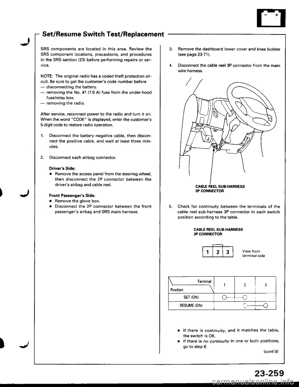
Remove the dashboard lower cover and knee bolster(see page 23-71).
Disconnect the cable reel 3P connector trom the main
wire harness.
CABLE REEL SU&HARNESS3P CONNECTOR
Check for continuiw between the terminals of the
cable reel sub-harness 3P connector in each switch
position according to the table.
CAALE REEL SUB.HARNESS3P CONNECTOR
terminalside
lf there is continuity, and it matches the table,
the switch is OK.
lf there is no continuity in one or both positions,
go to step 6.(cont'd)
Terminal
t"*-
---\23
SET {ON)oC
RESUME (ON}o
23-259
Page 1315 of 1681
Gruise Control
- Set/Resume Switch Test/Replacement {cont'dl
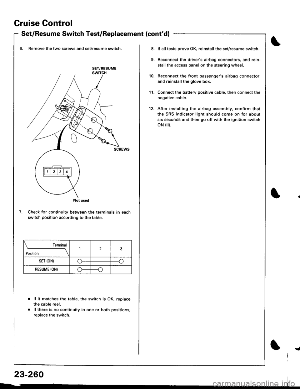
6, Remove the two screws and sevresume switch.
Check for continuity between the terminals in each
switch position according to the table.
lf it matche$ the table, the switch is OK. replace
the cable reel.
lf there is no continuity in one or both positions,
reolace the switch.
Not used
7.
Terminal
t*n*------l23
SET {ON)G----o
RESUME (ON}o----o
lf alltests prove OK, reinstallthe sevresume switch.
Reconnect the driver's airbag connectors, and rein'
stall the access panel on the steering wheel.
Reconnect the front passenger's airbag connector,
and reinstallthe glove box.
Connect the battery positive cable, then connect the
negative cable.
After installing the airbag assembly, confirm that
the SRS indicator light should come on for about
six seconds and then go off with the ignition switch
oN flr).
11.
12.
!a
Page 1339 of 1681
Disconnecting the Airbag Connector(s)
!@ To prevent accidental airbag dsploymcnt, turn ths ignition switch OFF, disconnect the negrtive battory
able, and wait three minut€s before disconnesting any SRS Glnnoqto.s.
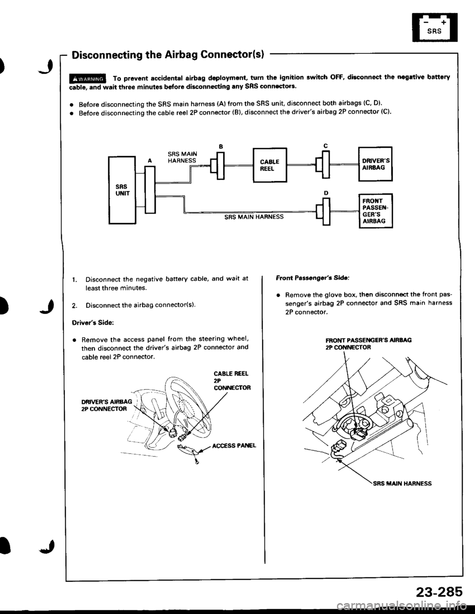
. Before disconnecting the SRS main harness {A)from the SRS unit, disconnect both airbags (C, D).
. Before disconnecting the cable reel 2P con nector ( B). disconnect the driver's airbag 2P connector (C).
)
1. Disconnect the negative baftery cable. and wait at
least three minutes.
2. Disconnect the airbag connector(s).
Driver's Side:
. Remove the access panel from the steering wheel,
then disconnect the driver's airbag 2P connector and
cable reel 2P connector.
CABLE REEL2?CONNECTOR
Front Ps$sngar'3 Sid.:
. Remove the glove box. then disconnect the front pas-
senger's airbag 2P connector and SRS main harness
2P connector,
\,./AccEssPANEL
23-2A5
Page 1371 of 1681
)
Airbag
Replacement
After a collision in which the airbags were deployed, the
airbag assemblies and the SRS unit must be replaced'
!!@ stole a removed sirbag with the pad sur'
ii6--up. tt tle sirbag i5 impropetly stored lace down,
accidental doploym€nt Gould propol tho unit with
enough lorce to cause serious iniury.
CAUTION:
. Do not install usad SRS parts from another vehicle'
When repairing, u3e only new SRS parB.
. Carefully inspsct the airbag befor€ you iGtall it Do
not install 8n airbag that shows signs of being
dlopped or improperly handled' such a3 dsnts,
cracks or defolmalion
. Always disconnact lhe airbag conneqtor{s) when the
harn$s is disconn€ctsd.
. Do not dislsembla or tlmp€r with thr sirbag
1. Make sure vou have th€ anti-theft code for the radro,
then write down the frequencies for the radio's pre-
set buttons.
2. Disconnect the battery negative cable, then discon-
nect the positive cable from the battery, and wait at
least three minutes.
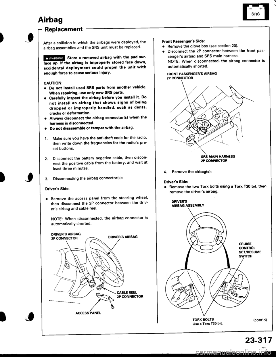
3. Disconnecting the airbag connector(s):
Driver's Side:
a Remove the access panel from the steering wheel,
then disconnect the 2P connector between the driv-
er's airbag and cable reel.
NOTE: When disconnected, the airbag connector is
automaticallY shorted.
)
23-317
2t @aa-gY(x
Front Pa3ienget's Sidel
. Remove the glove box (see section 20).
. Disconnect the 2P connector betwsen tha front pas-
senger's airbag and SRS main harness.
NOTE: When disconnected, the airbag conngctor is
automaticallY shoned
FBONT PASSENGER'S AIRBAG2P CONNECTOR
4. Remove the airbag(s):
Drivar's Side:
. Bemove the two Torx bolts using ! Torr T3O b{t, thGo
remove the driver's airbag'
DRIVER'SAIRBAG ASSEMBLY
CRUISECONINOLSET/RESUMEswtTcH
TORX BOLTSti3e a To T30 bit.(cont'd)
Page 1373 of 1681
I
I
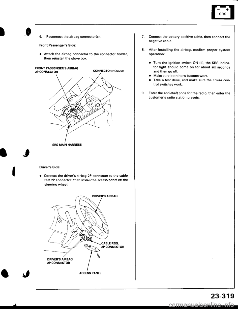
6. Reconnect the airbag connector(s).
Front Passenger's Side:
. Attach the airbag connector to the connector holder.
then reinstallthe glove box.
CONNECTOR HOLDER
Driver's Side:
. Connect the driver's airbag 2P connector to the cable
reel 2P connector, then rnstall the access panel on the
steering wheel.
\,
23-319
7.Connect the baftery positive cable, then connect thenegative cable.
After installing the airbag, confirm proper system
operal|on:
. Turn the ignition switch ON (ll); the SRS indica-
tor light should come on for about six seconds
and then go off.
. Make sure both horn buttons work.
. Take a test drive, and make sure the cruise con-
trol switches work.
Enter the anti-theft code for the radio. then enter the
customer's radio station presets,
9.
Page 1374 of 1681
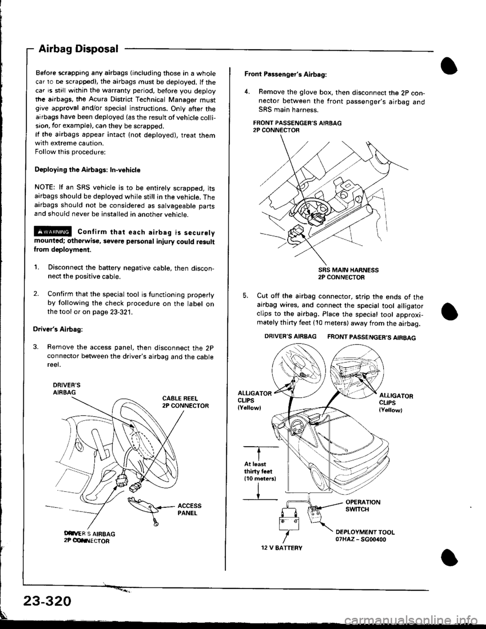
Before scrapping any airbags (including those in a whole
car ro be scrappedl, the airbags must be deployed. lf the
car is still within the warranty period, before you deploy
the airbags, the Acura District Technical Manager mustgive approval and/or special instructions. Only after theairbags have been deployed (as the result of vehicle colli-
sion, for example). can they be scrapped.
lf the airbags appear intact (not deployed). treat themwith extreme caution.
Follow this procedure:
Deploying the Airbags: In"vehicle
NOTE: lf an SRS vehicle is to be entirely scrapped. itsairbags should be deployed while still in the vehicle. Theairbags should not be considered as salvageable parts
and should never be installed in another vehicle.
E@ Contirm that each airbsg is securelymounted; otherwise, severe personal iniury could resultfrom deployment.
1. Disconnect the battery negative cable, then discon-nect the positive cable.
2. Confirm that the special tool is functioning properly
by following the check procedure on the label onthe tool or on page 23-321.
Driver's Airbag:
3. Remove the access panel, then disconnect the 2pconnector between the driver's airbag and the cablereel.
DRIVEE'SAIRBAGCABLE REEL2P CONNECTOR
Airbag Disposal
Oit,ER S AIREAG2P OdIIIECTOR
\\+- AccEss
I
PANEL
12 V EATTERY
Front Passenger's Airbag:
4. Remove the glove box, then disconnect the 2p con-nector between the front passenger's airbag andSRS main harness.
FRONT PASSENGER'S AIRBAG2P CONN€CTOR
SRS MAIN HARNESS2P CONNECTOR
5. Cut off the airbag connector, strip the ends ot theairbag wires. and connect the special tool alligatorclips to the airbag. Place the special tool approxi-mately thirty feet (10 meters) away from the airbag.
DRIVER'S AIRBAG FRONT PASSENGER'S AIRBAG
ALLIGATORCLIPSlYellowl
ALLIGATORCLIPSlYellowl
-T--
IAt leastthiny tcet110 meters)
IV
23-320
Page 1375 of 1681
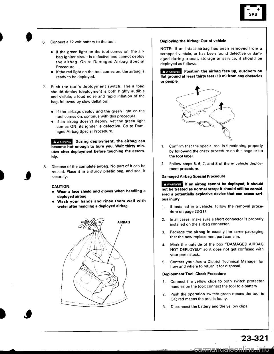
)6.
7.
8.
Connect a 12 volt battery to the tool:
. lf the green light on the tool comes on, the alr-
bag igniter circuit is defective and cannot deploy
the airbag. Go to Damaged Airbag Specia I
Procedure.
. lfthe red light on the tool comes on, the airbag is
ready to be deployed.
Push the tool's deployment switch The airbag
should deploy (deployment is both highly audible
and visible; a loud noise and rapid inflation of the
bag, followed by slow deflation).
. lf the airbags deploy and the green light on the
tool comes on, continue with this procedure
. lf an airbag doesn't deploy. yet the green light
comes ON, its igniter is defective. Go to Dam-
aged Airbag Special Procedure.
!!@ During deployment, the airbag c8n
become hot enough to burn you Wait thirtY min-
ut€s after d€ployment befote touching the assem-
blv.
Dispose of the complete airbag. No part of it can be
reused. Place it in a sturdy plastic bag, and seal it
securery.
CAUTION:
. wear a lace shield and gloves when handling a
deployed airbag.
. Wash your hands and rinse them well with
water after handling a deployed sirbag
)
Deploying the Airbag: Out-ot-vehicle
NOTE: lf an intact airbag has been removed from a
scraDDed vehicle, or has been found defective or dam-
aged during transit, storage or service, it should be
deoloved as follows:
@@ Position th€ airbag laca up. outdoors on
tlat ground at l€ast thirty leet (10 m) ftom any obstacles
or people.
1. Confirm that the special tool is functioning properly
by tollowing the check procedure on thls page or on
the tool lab€|.
2. Follow steps 5, 6, 7, and 8 ol the in.vehicle deploy'
ment orocedure.
Damaged Airbag Sp€citl Procedurc
!@ [ an airbag cannot be d.ploytd, h 3hoold
not be lreated as normal scrap; it should 3till b. corlrkl
ered a polentially sxplosive device that can clura tari
ous iniury.
1. lf installed in a vehicle, follow the removal proce-
dure on page 23-317.
2. ln all cases, make sure a short connector is properly
installed on the airbag connector.
3. Package the airbag in exactly the same packaging
that the new replacement part came In.
4. Mark the outside of the box "DAMAGED AIRBAG
NOT DEPLOYED" so it does not get confused with
your Parts stock.
5. Contact your Acura District Technical lvanager for
how and where to return it for disposal.
Deployment Tool: Ch€ck Ptocedure
1. Connect the yellow clips to both switch protector
handles on the tool; connect the tool to a battery
2. Push the operation switch: green means the tool is
OK; red means the tool is faultv.
3. Disconnect the battery and the yellow clips
23-321
Page 1383 of 1681
).1
Contents
How to Use This l\.4anual 1Circuit Schematics (see Circuit Index)Fuse/Relaylnformation 6ComponentLocation Photographs 201
Connector Cavity Numbers 202Connectorldentification 203
Ground-to-Components Index 6-6Wire Harness Routing 203Circuit ldentification lor ln-Line and Fuse Box Connectors
Circuit Index
Air conditionerAir delivery 61Blower controls 60Compressor controls 62Fans 63Anti-lock brake system (ABS) 44A/T gear position indicator 89Automatic transmission controls'98199 models 39'00 models 39-4Back-up lightsHatchback 110Sedan 110- 1Brake system indicator light
USA 71Canada 71-1Brake lightsHatchback 110-6Sedan 110-7Cargo area light (Hatchback) 114-3Ceiling light 114-2Charging system 22Cigarette lighter 155
Clock 154Condenser fan 63Console lights 114Cruise control 34Dash lights 1 14Daytime running lights 110-8Door open indicator 114-2Engine coolant temperature gauge 81Engine oil pressure indicator light 72Fog lights 110-14Front parking lights 110-11Front side marker lights 110-11Fuel gauge 81Fuse/relay boxUnder-dash 6Under-hood 6-3Under-hood ABS 6-5Gauges 81Glove box light 114Ground distribution 14Ground-to-Componentsindex 6-6Hatch open indicator '114-3
Hatch opener '134
Hazard warning lightsHatchback 'l l0-2Sedan 110-4Headlights 1'10-8Headlight switch 100HeaterAir delivery 61Blower controls 60Fanswith A,/C 63without A,/C 63-2Horns 40lgnilion key reminder 73lgnition system 20
204
lmmobilizer system ('00 model) 132lndicators 80Integrated control unit 70Interlock system'98199 models 138'00 models 138-1License plate lightsHatchback 110-12Sedan 110-13Lights-on reminder 73Low fuel indicator light 74l\,4aintenance reminder light 83l\iloonroof 122Odometer 81-1Power antenna 151Power distributionBattery to ignilion switch, fuses, and relays
Fuses to relays and components 10-2Power door locksHatchback '130
Sedan 130-2Power mirrorsHatchback 141Sedan 141-1Power windowsHatchback 120Sedan 120-2Programmed fuel injection system (PGM-Fl)'98199 models 23'00 models 24Radiator fanwith tuC 63without A,/C 63-2Rear parking lightsHatchback 110-12Sedan 110- 13Rear window defogger 64Seat belt reminder 73Security system 133Speedometer Il-1Spotlights 114-2Starting syslemAutomalictransmission 21l\.4anualtransmission 21-1Stereo sound system 150Supplemental restraint system (SRS) 47Tachometer 81- 1TaillightsHatchback 110-12Sedan 110-13Trailer lighting conneclor 118Trunk lid open indicator 114-3Trunk light (Sedan) 114-3Turn signal lightsHatchback 110-2Sedan 110-4Vehicle speed sensor (VSS) 33Wiper/washerFront 91Rear 92
10
).1
I
Xr
12Fg oAmerican Honda Motor Co., Inc. - All Rights Reserved Service Communications 275 pages