1998 HONDA INTEGRA brake sensor
[x] Cancel search: brake sensorPage 726 of 1681

Front Suspension
Knuckle/Hub (cont'd)
Knuckle lnstallation
1. lnstall the knuckle on the driveshaft.
2. lnstall the knuckle on the lower arm and the tie-rod,
then tighten the nuts and install new cotter pins.
CAUTION:
. Be carelul not to damage tho ball ioint boot.
a Torque the castls nut to the lowel torque spgci-
fication, then tight€n it only far enough to align
the slot with the pin hole. Do not align the nut
by loosening.
NOTE: Wipe off the grease before tightening the
nut at the ball joint.
NUT
ri
10 x 1.25 mm4il N.m (4.{ kgtm,32lbf.ftl
On reassembly,bend the cotter pin
as shown.
CASTLE NUT12 x 1 .25 mm49 - 59 N.m (5.0 - 6.0 kgf m, 36 -,|i| lbf ft)
3. Install the knuckle on the upper arm, then tighten
the castle nut and install a new cotter Din.
COTTER PINReplace.On reassembly,bend the cotter pin
CASTLE NUT12 x 1.25 mm39 - 47 N.m{4.0 - 4.8 kgf.m,29 - 3s rbr.ft)
;
, 'ar
COTTER PIN
18-16
4.Install the wheel sensor with the sensor mounting
bolts (tor vehicles with ABS).
lnstall the sensor wire with the two 5 mm bolts (for
vehicles with ABS).
NOTE: Be careful when installing the sensors to
avoid twisting wires.
6 mm BOLTS9.8 N.m 11.0 kgf.m,7 lbf.ftl
v_)
SENSOR MOUNTINGBOLTS9.8 N.m (1.0 kgf.m,7.2 lbl.ftl
6. lnstall the brake disc with the 6 mm brake disc retain-
Ing screws.
NOTE: Before installing the brake disc, clean the
mating surfaces of the front hub and the brake disc.
6 mm BRAKE DISCRETAINING SCREWS9.8 N.m 11.0 kgl.m, 7.2 lbf'ftl
Page 775 of 1681

Anti-lock Brake System {ABS}
Speciaf Tools ............... 19-24
Component Locations,...........,..,........... 19-25
Anti-lock Brake System (ABSI
Features/Construction ....................... 19-2G
Circuit Diagram ........... 19-30
ABS Control Unit Terminal
Arrangement ........... 19-32
Troubleshooting Precautions ................ 1g-35
Diagnostic Trouble Code (DTC)
DTC Indication (SCS Mode) ............... t9-37
DTC Erasure {MES Mode) .................. 19-38
b Troubleshooting Index ...................... 19-39- Troubleshooting
ABS Indicator Does Not
Come On .............. 19-40
ABS Indicator Does Not
Go Off .............. ..... 19-42
DTC 11, 13, 15. 17:
Wheel Sensor (Open/Short to Body
Ground/Short to Power) ............... l9-44
DTC 12. 14, 16, 18:
Wheel Sensor (Electrical Noise/
Intermittent Interruption) ..........,.. 19-45
DTC21 -24:
Pulser ...,.......... ..... 19-46
DTC 31 - 38:
Solenoid .............. 19-47
DTC 41 - 44:
Wheel Lock .......... 19-50
DTC 51:
Motor Lock .......... 19-51
DTC 52:
Motor Stuck OFF ...................,........ 19-52
DTC 53:
Motor Stuck ON ............................. 19-55
DTC 54:
Fail-safe Relay ................................ t9-57
DTC 61.62:
lgnition Voltage ............................. 19-59
DTC 71:
Different Diameter Tire .................. 1 9-60
DTC 81:
Gentral Processing
Unit {CPU} ............ 19-60
Modulator Unit
Bemoval/lnstallation ......................... 19-61
ABS Control Unit
Replacement ............ 19-62
Pulsers/Wheel Sensors
Inspection ................ 19-62
Wheel Sensors
Replacement .,.......... 19-63
Page 784 of 1681
![HONDA INTEGRA 1998 4.G Workshop Manual ABS Gontrol Unit Terminal Arrangement
ABS CONTROL UN]T 22P CONNECTOR
Wire side oI female t6rminals
Terminal
numbel
Wire
Golor
Terminsl sign
{Terminal
namet
Description
Measurgmgnt
TerminalConditions
{ HONDA INTEGRA 1998 4.G Workshop Manual ABS Gontrol Unit Terminal Arrangement
ABS CONTROL UN]T 22P CONNECTOR
Wire side oI female t6rminals
Terminal
numbel
Wire
Golor
Terminsl sign
{Terminal
namet
Description
Measurgmgnt
TerminalConditions
{](/manual-img/13/6069/w960_6069-783.png)
ABS Gontrol Unit Terminal Arrangement
ABS CONTROL UN]T 22P CONNECTOR
Wire side oI female t6rminals
Terminal
numbel
Wire
Golor
Terminsl sign
{Terminal
namet
Description
Measurgmgnt
TerminalConditions
{lgnition swhch ON {ll}}Voltage
1BLK/WHTGND3(Ground 3)
Ground1.GNDBelow 0.3 V
4GRN/REDPARK
{Parking)
Detects parking brake
switch signal4-GNDParking
brake
PulledBelow 0.3 V
Battery voltage
LT GRN/
BLK
FLW (-)
{FronLleft
wheel negative)
Detects left-front wheel
sensor srgnal
0.053 V or
above
0sci\oscope:
0.15 Vp-p or
above
7GBN/ORN
FLW (+)
(Front-left
wheel positive)- | Turn wheel at
E
1 turntsecona
l'GRN
FRW (-)
(Front-right
wheel negative)
Detects right-f ront wheel
sensor slgnal
8-9
1 FR\N (+)
I \GRN/BLK (Front-right
I I wheelpositiveStops0.25 - 1.15 V
10GRN/WHTSTOPDetects brake switch signal1O.GNDBrake pedalDepressedBaftery voltage
ReleasedBelow 0.3 V
11BLK/TELtG2
(lgnition 2)
Power source for activating
the system11-GNDlgnition
switch
oN {I)Battery voltage
Start (lll)Below 0.3 V
19-32
Page 1058 of 1681
J
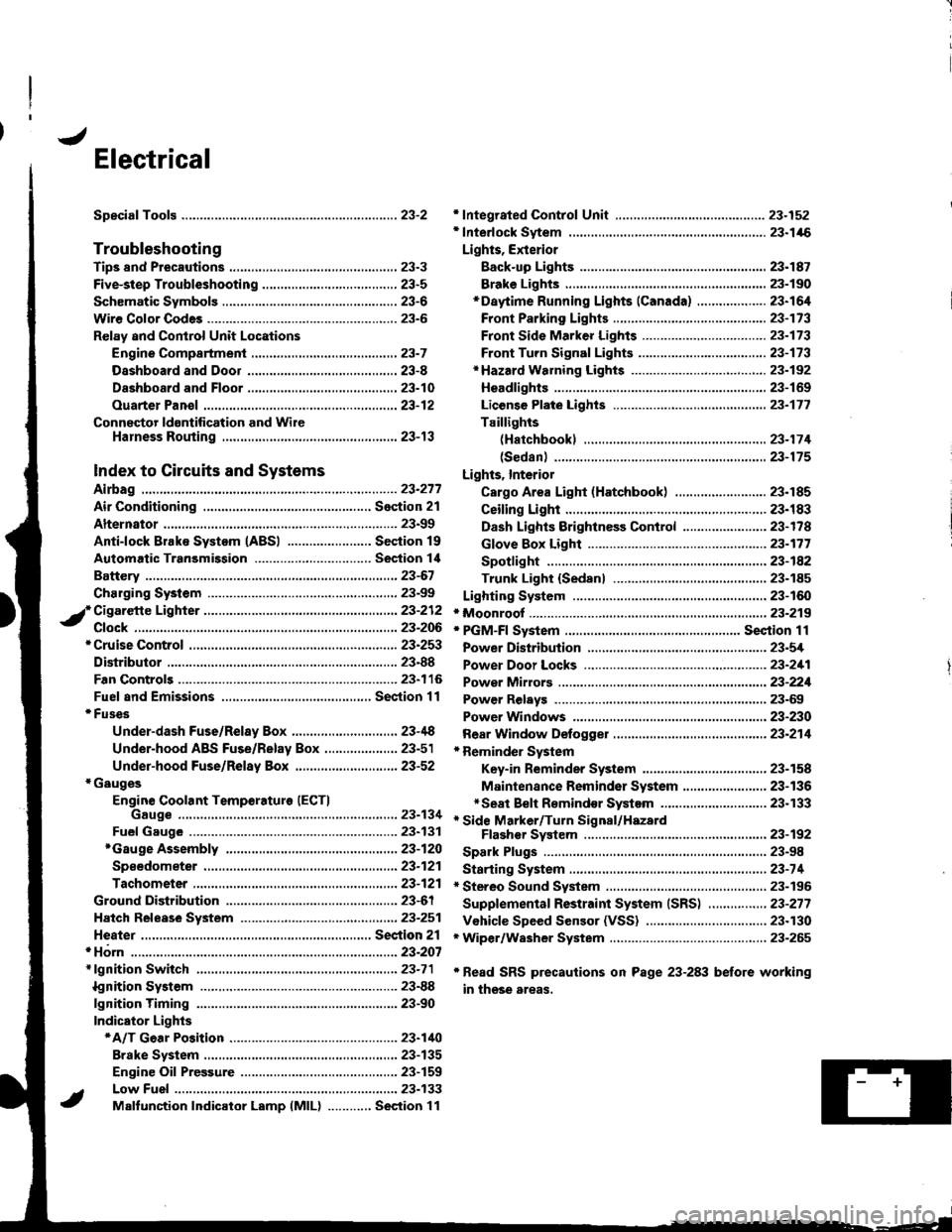
Electrical
Speciaf Toofs ..........................23-2
Troubleshooting
Tips 8nd Precautions .......................,..,.,.,.,.,......,..., 23-3
Five-step Troubleshooting ............,......,.,.,...,..,....., 23-5
Schsmatic Svmbols ...............23-6
Wire Color Code3 .. ................. 23-6
Relay and Control Unit Locations
Engine Compartment ......,.,.................,.,.,.,.,.,,,, 23-7
Dashboard and Door .........,...........,.....,.,....,.,.... 23-8
Dashboard and Floor ......................................... 23-10
Ouarter Pan€f .,,.,...,.,..,...,,,23-12
Connector ldontification and WireHarness Routing ......,.,......23-'13
Index to Circuits and Systems
Airbag
* Integrated Control Unit .....,.,.,.....23-152* Interlock Sytem .,...,.,...........,. 23.146
Lights, Exterior
Eack-up LighB ..................23.187
Brake Ligh$ ......................23-190*Daytime Running Lights (Canada) ................... 23"164
Front Parking Lights .......................................... 23-173
Front Side Marker Lights .................................. 23-173
Front Turn Signal Lights ..................-.......,...,.,. 23-173* Hazard Warning Lights ....................,........,....... 23-192
Headlights.....23-169
23-253 powerDistribution..................... 23-5/r
Air Conditioning.....,....... Soction 21
Alternator ..........,................... 23.99
iCigarette Lighter .........23-212
*Cruise Control
Distributor
'.'.,.'.'.,.'...,,,,.,''.'.,.',.'''.' 23.277
.............................. 23.88
................... 23-90lgnition Timing ......
Indicator Lights
Key-in Reminder System
Maintenance Reminder System*Seat Belt R€mindor System .,...........................* Side Marker/Turn Signal/HazardFlashcr Svstem .................23-192
Spark Plugs ............................23-98
Starting System .....................23-74* Stereo Sound System ...,......,..........,...,......,.,.,.,..,., 23-196
Supplemental Restraint System (SRS) ................ 23-277
Vshicle Speed Sensor (VSS) ................................. 23.130r Wiper/Washer System .........................................., 23-265
*Read SRS precautions on Psge 23-283 before working
in those areas,
23-154
23.136
23"133
Page 1077 of 1681
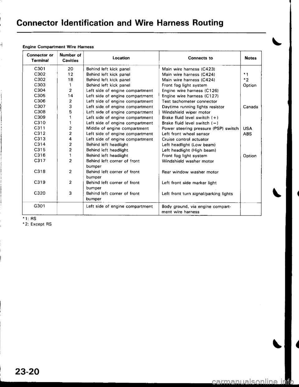
Connector ldentification and Wire Harness Routing
Engine Compartment Wire Halness
nll
Connectoa ot
Terminal
Number of
CavitiesLocationConnects toNotes
c301
c302
c 302
c303
c304
c306
c307
c308
c309
c310
c3l 1
c312
c314
c316
c317
c318
c319
c320
20
't8
1
14
2
3
5
1
1
2
2
4
2
2
1
2
2
2
3
Behind left kick panel
Behind left kick panel
Behind left kick panel
Behind left kick panel
Lett side of engine compartment
Lett side of engine companment
Lett side of engine compartment
Left side of engine compartment
Left side of engine compartment
Left side of engine compartment
Left side of engine compartment
Middle of engine compartment
Lett side of engine companment
Left side of engine compartment
Behind left headlight
Behind left headlight
Behind left headlight
Behind left corner of front
DUmper
Behind left corner ol front
bumper
Behind lett corner of front
bumper
Behind left co.ner of lront
bumper
Main wire harness (C423)
Main wire harness {C424)
N4ain wire harness (C424)
Front fog light system
Engine wire harness (C126)
Engine wire harness (C'127)
Test tachometer connector
Daytime running lights resistor
Windshield wiper motor
Brake f luid level switch (+ )
Brake f luid level switch ( - )
Power steering pressure (PSP) switch
Lett front wheel sensor
Cruise control actuator
LeIt headlight (Low beam)
Lett headlight {High beam)
Front fog light system
Windshield washer motor
Rear window washer motor
Left front side marker light
Left front turn signal/parking lights
Option
Canada
USA
ABS
Option
G301Lelt side of engine compartmentBody ground, via engine compart-
ment wire harness
23-20
Page 1177 of 1681
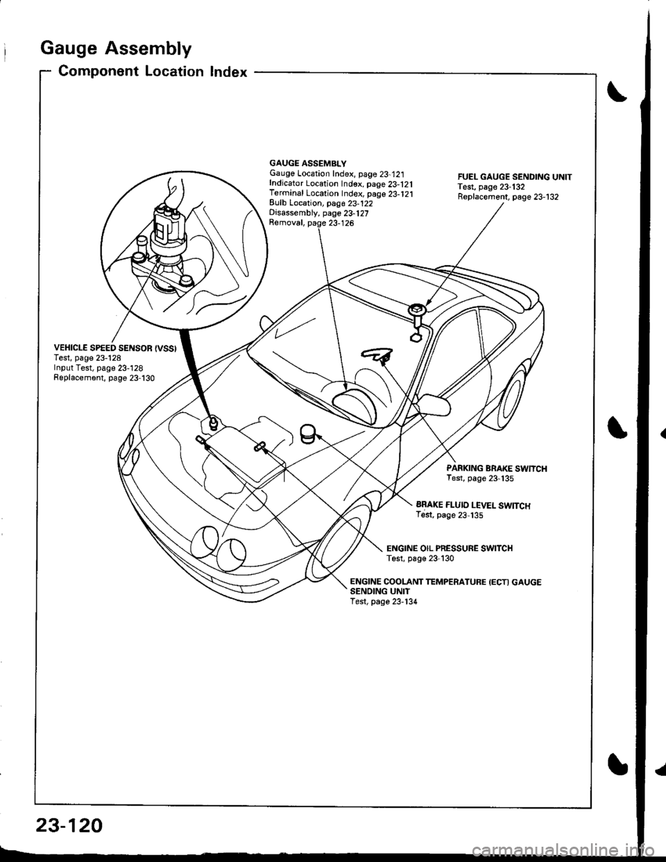
Gauge Assembly
Component Location Index
VEHICLE SPEED SENSOR {VSSITest, page 23-128Input Test, page 23-128Replacement, page 23-130
GAUGE ASSEMBLYGauge Location Index, page 23-12:|fndicator Location Index. page 23-121Terminal Location Index, page 23-121Eulb Location, pag6 23-122Disassembly, page 23-127Removal, paqe 23-126
FUEL GAUGE SENDING UNITTest, page 23-132Replacement, page 23-132
PARKING BRAKE SWNCHTest, page 23-135
ARAKE FLUID LEVEL SWITCHTest, page 23,135
ENGINE OIL PRESSURE SWITCHTest, p6ge 23-130
ENGINE COOLANT TEMPERATUFE IECTI GAUGESENOING UNITTest, page 23-134
23-120
Page 1205 of 1681
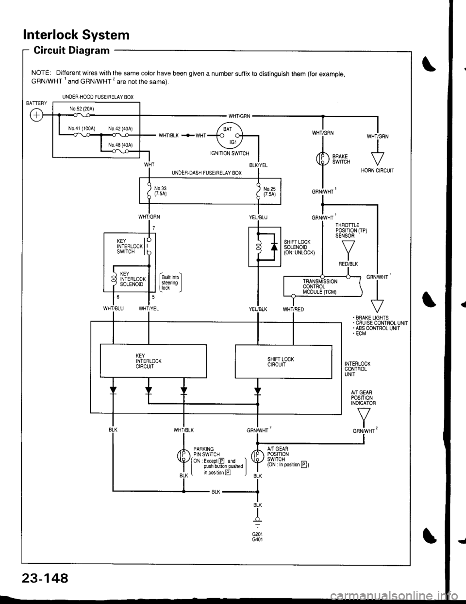
lnterlock System
Circuit Diagram
NOTE: Different wires with the same color have been given a number suflix to distinguish them (for example,cRNA/VHT I and cRNMHT '� are not the same).
WHT/ BLK .-- WHI
cnrruvgr'
+. BRAKE LIGNTS.CSUISE CONTROLUNIT. ABS COIITROL UNIT' ECM
INTEBLOCKCONTROLUNIT
A]'IGEARPOStTIONINOICATOR
v
t,
UNDER-HOOO FUSEi RELAY BOX
N0.41 (100A) N0.42 (404)
YEUBLUcnrivrr '
WHT/BLU
KEYINTERLOCKswtTcH
THBOTTLEPosrT|0N (TP)SENSOR
f7
IRED/BLK
(Cjl :in posiron E t
23-14A
Page 1206 of 1681
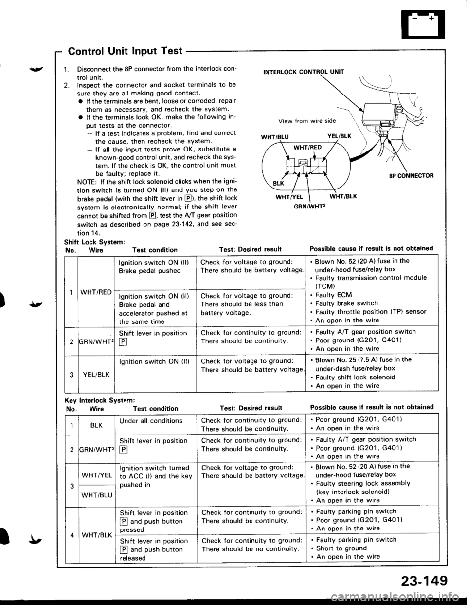
){r/
Control Unit Input Test
1. Disconnect the 8P connector from the interlock con-
trol unit.
2. lnspect the connector and socket terminals to be
sure they are all making good contact.
a It the terminals are bent, loose or corroded, repair
them as necessary, and recheck the system.
a lf the terminals look OK, make the following in-
put tests at the connector.- lf a test indicates a problem, tind and correct
the cause, then recheck the system.- lf all the input tests prove OK, substitute a
known-good control unit, and recheck the sys-
tem. lf the check is OK, the control unit must
be faulty; replace it.
NOTE: lf the shift lock solenoid clicks when the igni-
tion switch is turned ON (ll) and you step on the
brske Dedal (with the shift lever in E). the shift lock
system is electronically normal; if the shift lever
cannot be shifted from fl, test the 46 gear position
switch as described on page 23-142, and see sec-
tion 14.
Shift Lock System:
No. Wire Test condition
No. WireTest condition
Test: Desired resultPossible causs it result is not obtained
Test: Dcsired lesultPossible cause it result is not obtainsd
INTERLOCK CONTROL UNIT
GRN/wHT2
1WHT/RED
lgnition switch ON (ll)
Brake pedal pushed
Check for voltage to ground:
There should be battery voltage
Blown No. 52 {20 A) fuse in the
under-hood fuse/relaY box
Faulty transmission control module
(TCM)
Faulty ECM
Faulty brake switch
Faulty throttle position (TP) sensor
An open in the wire
lgnition switch ON (ll)
Brake pedal and
accelerator pushed at
the same me
Check for voltage to ground:
There should be less than
battery voltage.
tGRN/WHT'
Shift lever in position
E
Check tor continuity to ground:
There should be continuity.
Faulty A/T gear position switch
Poor ground {G20'1 , G401)
An open in the wire
3YEL/BLK
lgnition switch ON (ll)Check for voltage to ground:
There should be battery voltage
Blown No. 25 (7.5 A) fuse in the
under-dash fuse/relay box
Faulty shift lock solenoid
An open in the wire
Key Int€rlock Systcm:
BLKUnder all conditionsCheck lor continuity to ground:
There should be continuitY.
. Poor ground (G201, G401). An open in the wire
GRNiWHT'
Shift lever in position
E
Check for continuity to ground:
There should be continuity.
Faulty A/T gear position switch
Poor ground {G2O1, G401 }
An open in the wire
3
WHT/YELlgnition switch turned
to ACC (l) and the key
pushed in
Check tor voltage to ground:
There should be battery voltage.
Blown No. 52 (20 A) fuse in the
under-hood fuse/relaY box
Faulty steering lock assemblY
(key interlock solenoidl
An open in the wireWHT/BLU
4WHT/BLK
Shift lever in position
E and push button
pressed
Check for continuity to ground:
There should be continuity.
Faulty pafking pin switch
Poor ground (G2O1, G4O 1)
An open in the wire
Shift lever in position
E and push button
reteaseo
Check for continuity to ground:
There should be no continuity.
Faulty parking pin switch
Short to ground
An open in the wire
I'
23-149