Page 778 of 1681

.,i
,I
Anti-lock Brake SYstem (ABS)
when the brake pedal is depressed during driving, the wheels can lock before the vehicle comes to a stop. In such an event.
the maneuverability of the vehicle is reduced if the front wheels are locked, and the stability of the vehicle is reduced if the
rear wheels are locked, creating an extremely unstable condition. The ABS precisely controls the slip rate o{ the wheels to
ensUre maximum grip force from the tires, and it thereby ensures maneuverbiIity and stabiIity of the vehicIe.
The ABS calculates the slip rate of the wheels based on the vehicle speed and the wheel speed. then it controls the brake
fluid oressure to attain the target slip rate
Features/Gonstructio n
Grip Foact ot Ti.c tnd Rotd Surfuco
COEFFICIEUT OFFNIG"TPN
Slip Rrtr
BRAKINGSTART POINT
i'l
A: f'3t rp withoul .lip
B: SIDp.d dirt.nc.G Actu.ldtt nc.io.top
sr.n arrr = f =
STOP POINTTARGET SUP RATE
SUP FATEVEHICT.C S'EEO - wlCEL SPEED
NO: Notm.lly oP.n
l{C: Noirnrly qo..d
19-26
Page 780 of 1681

Anti-lock Brake System (ABS)
Features/Construction (cont'd)
ABS Modulatol
The ABS modulator consists of the inlet solenoid valve, outlet solenoid valve, reservoir, pump, pump motor and the
damping chamber.
The modulator reduces the caliper fluid pressure directly. lt is a circulating-type modulator because the brake fiuid circulates
through the caliper, reservoir and the master cylinder.
The hydraulic control has three modes: pressure reduction, pressure retaining and pressure intensiiying
The hvdraulic circuit is the independent four channel-type, one channel tor each wheel'
L-__
RF LR
Pressure intensifying mode: Inlet valve open, outlet valve closed
Master cvlinder fluid is pumped out to the caliper.
Inlet valve closed, outlet valve closed
Caliper fluid is retained by the inlet valve and outlet valve.
lnlet valve closed, outlet valve open
Caliper fluid flows through the outlet valve to the reservolr'
When starting the pressure reduction mode, the pump motor is ON.
When stopping ABS operation, the pump motor is OFF.
The reservoir fluid is pumped out by the pump, through the damping chamber, to the master
cylinder.
\
Pressure retaining mode:
Pressure reduction mode:
Motor operation mode:
sott orD vALvE
@@-@@
TASIEF CYLI'OEF
19-24
Page 788 of 1681

Troubleshooting Precautions
Kickback
L The motor operates when the ABS is functioning, and the fluid in the reservoir is forced out to the master cylinder,
causing kickback at the brake pedal.
Pump Motol
1. The pump motor operates when the ABS is functioning.
2. The ABS control unit checks the pump motor operation during initial diagnosis and when the vehicle is started. You
mav hear the motor operate at this time, but it is normal
Brake Fluid Replacement/Air Bleeding'1. Brake fluid replacement and air bleeding procedures are the same as vehicles without ABS. To ease bleeding, start
with the front wheels.
Troubleshooting
1. The troubleshooting flowcharts procedures assume that the cause of the problem is still present and the ABS indica-
tor is still on. Following the flowchart when the ABS indicator does not come on can result in incorrect diagnosis.
2. Ouestion the customer about the conditions when the problem occurred, and try to reproduce the same conditions
for troubleshooting.
Find out when the ABS indjcator came on. such as during initial diagnosis. during ABS control, after ABS control,
when vehicle speed was at a certain speed, etc.
3, When the ABS indicator does not come on during the test-drive, but troubleshooting is performed based on the DTC,
check for loose connectors, poor contact at the terminals, etc. before you start troubleshooting'
4. After troubleshooting, erase the DTC and test-drive the vehicle. Be sure the ABS indicator does not come on.
5. The connector illustrations show the female terminals with a single outline and the male terminals with a double outline.
Page 813 of 1681

Modulator Unit
Removal/lnstallation
CAUTION:
. Do not spill brake fluid on lhe vehicle; it may damage the paint; il brake fluid does contact the paint, wash it offimmediately with water.
. Tak€ care notto damage or delorm the brake lines during removal and installation.. To provont the brake fluid ftom flowing, plug and cover the hos€ ends and ioints with a shop towel or equiyalent material.
Removal
1. Disconnect the modulator unit and DUmD motor connectors.
2. Disconnect the brake lines, then remove the modulator unit.
Installation
1. lnstall the modulator unit, then connect the brake lines. Tighten the flare nuts to 15 N.m (1.5 kgf.m, 11 lbf.ft).2. Connect the modulator unit and pump motor connectors.
3. Bleed the brake system, starting with the front wheels.
4. Start the engine, and check that the ABS indicator goes off.
5. Test-drive the vehicle, and check that the ABS indicator does not come on.
From master cylinder
from master cylinderprimary side
PUMP MOTOB CONNECTOR
MOUNT
UNlT
MODULATOR UNIT CONNECTOR
toright front
8 mm EOLT22 N.m {2.2 kg[.m, 16 lbl.ftl
6 mm NUT9.8 N.m 11.0 ks{.m,7.2lbtftl
9-6
Page 1177 of 1681
Gauge Assembly
Component Location Index
VEHICLE SPEED SENSOR {VSSITest, page 23-128Input Test, page 23-128Replacement, page 23-130
GAUGE ASSEMBLYGauge Location Index, page 23-12:|fndicator Location Index. page 23-121Terminal Location Index, page 23-121Eulb Location, pag6 23-122Disassembly, page 23-127Removal, paqe 23-126
FUEL GAUGE SENDING UNITTest, page 23-132Replacement, page 23-132
PARKING BRAKE SWNCHTest, page 23-135
ARAKE FLUID LEVEL SWITCHTest, page 23,135
ENGINE OIL PRESSURE SWITCHTest, p6ge 23-130
ENGINE COOLANT TEMPERATUFE IECTI GAUGESENOING UNITTest, page 23-134
23-120
Page 1192 of 1681

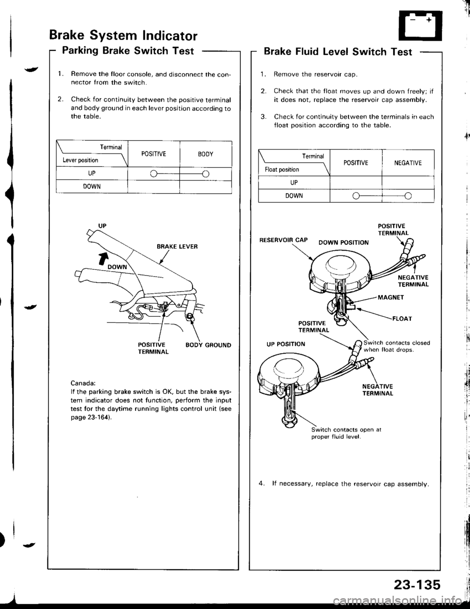
Brake System Indicator
Parking Brake Switch Test
1.Remove the Iloor console, and disconnect the con-nector from the switch.
Check for continuity between the positive terminal
and body ground in each lever position according tothe table.
2.
POSITIVE BODY GROUNDTERMINAL
Canada:
lf the parking brake switch is OK, but the brake sys-
tem indicator does not function, perform the input
test for the daytime running lights control unit {see
page 23-164).
Terminal
l"*rr*ril---ltPOSITIVEBODY
UPoo
DOWN
'il
--r '1i
T- +T
L.J
Brake Fluid LevelSwitch Test
Remove the reservoir cap.
Check that the float moves up and down freely; if
it does not, replace the reservoir cap assembly.
Check for continuity between the terminals in each
lloat position according to the table.
POStnVETERMINALRESERVOIR CAPDOWN POSITION
4l
NEGATIVETERMINAL
MAGNET
POSITTVETERMINAL
*----raoo,
Switch contacrs closedwhen float drops.UP POSITION
TIVETERMINAL
Switch contacts open atproper fluid level.
4. lf necessary, replace the reservoir cap assemblv.
| ermrnal
Float position \POSITIVENEGATIVE
UP
DOWNo--o
I
Page 1214 of 1681
M
lgnition switch at
START iIII)
Check for voltage to ground:
There should be battery voltage.
Blown No.31 (7.5 A) fuse in the
under-dash fuse/relay box
Faulty clutch interlock switch or
starter cut relay (M/T)
Faulty neutral position switch (A/T)
An open in the wire
2D
lgnition switch ON {ll).
brake fluid reservoir
full, and parking brake
tever oown
Connect to ground: Brake
system light should come on.
. Blown brake system light. An open in the wire
Bulb Check System (brake system light)
No. Terminal Test conditionTost: Desiled resultPossiblo cause if lesult is not obtained
)
)
23-157
Page 1222 of 1681

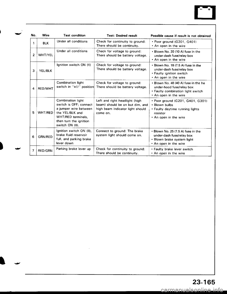
Tsst conditionTest: Desiled resultPossible cause it result is not obtained
)
BLKUnder all conditionsCheck for continuity to ground:
There should be continuity.
. Poor ground (G201 , G40l ). An open in the wire
2WHT/YEL
Under all conditionsCheck for voltage to ground:
There should be battery voltage.
. Blown No. 20 (10 A) fus€ in the
under-dash fuse/relay box. An open in the wire
YEL/BLK
lgnition switch ON (ll)Check for voltage to ground:
There should be battery voltage.
Blown No. 18 (7.5 A)fuse in the
under-dash fuse/relay box
Faulty ignition switch
An open in the wire
RED/WHT
Combination light
switch in "=D" position
Check for voltage to ground:
There should be battery voltage.
Blown No. 48 (40 A) fuse in the he
under-hood fuse/relay box
Faulty combination light switch
An open in the wire
WHT/RED
Combination light
switch is OFF; connect
a jumper wire between
the YEL/BLK and
WHT/RED terminals,
then turn the ignition
switch ON (ll).
Left and right headlight (high
beaml should be on but dim, and
high beam indicator light should
come on.
Poor ground (G20'1, G4O1, G301)
Blown bulbs
Faulty daytime running lights
resrstor
An open in the wire
6GRN/RED
lgnition switch ON (ll).
brake fluid reservoir
full, and parking brake
levef oown
Connect to ground: The b.ake
system light should come on.
Blown No. 25 (7.5 A) fuse in the
under-dash fuse/relay box
Blown brake system light
An open in the wire
'1RED/GRNParking brake lever upCheck for continuity to ground:
There should be continuity.
. Faulty brake lever switch. An open in the wire
23-165