Page 643 of 1681
Driveshafts
Reassembly (cont'dl
-6. Raise up the boot band tool to bend the free
end of the band 90 degrees to the clip. Center
punch the clip, then fold over the remaining tail
onto the clio.
- 7. Unwind the boot banding tool, and cut off the
excess free end of the band to leave a 5 - '10
mm (0.2 - 0.4 in) tail protruding from the elip.
HAMMER
5- 10 mm(0.2 - 0.a inl
16-12
- 8. Bend the band end by tapping it down with a
nammer.
NOTE:
. Make sure the band does not move.
. Remove any grease remaining in the surround-
ing surfaces.
Page 644 of 1681
E8r Clamp Type Boot Eand Installation:
Csnada model outboard joi]|t bands
-1. Install the ear clamp boot band by aligning the
tabs with holes in the band.
EAR CLAMP BANDReplace.
Close the ear portion of the band with a com-
mercially available boot band pincers.
BOOT AAND PINCERS(Commercially available)Oetiker 1098 or equivalent
POSTION
Measure the clearance between the closed ear
portion of the band.
Siandard:0-3 mm (0 - 0.12 in)
lf the band's, clearance is not within the standard,
close the ear portion of the band further.
NOTE:
. Make sure the band does not move.
. Remove any grease remaining in the surround-
ing surfaces.
16-13
Page 646 of 1681

Intermediate Shaft
Removal
Drain the transmission oil or fluid {see section 13 or
14t.
Remove the left driveshaft (see page 16-3).
Bemove the three dowel bolts.
Remove the intermediate sh8ft from the differential.
CAUTION: Hold the intermediate shaft horizontal
until it is clear ot th6 difforantirl to prevont damage
to thc ditf€rential oil seal.
7. Install the knuckle on the lower arm.
NOTE: Wipe off the grease before tightening the
nut at the ball joint.
CAUTION:
. Be careful not to damago the ballioint boot.
. Torque the castle nut to tho low€r torque speci-
tication, then tighten it only lar onough to align
th6 slot whh tho pin hols. Do not align the nut
by loosening.
,.<__coTTEF PtNCASTLE NUT12 x 1.25 mm49 - 59 N.m {5.0 - 5.0 kgf.m, 36 - t3 lbl.ft)
Beplace.On reassembly,bend the cotter pin
8. Install a new spindle nut, then tighten the nut.
9. Installthe front wheel with the wheel nuts.
NOTE: Before installing the wheel, clean the mating
surfaces of the brake disc and the wheel.
FRONT WHEELWH€EL NUT 12 x 1.5 mm108 N.m (11.0 kgt m,80lbf ft)
10.
NUT 22 x '1.5 mm181 N m 118.5 kgl.m, 134lbtftlNOTE: After tightening, use a drift tostake the spindle nut shoulderagainst the driveshatt.
Tighten the flange bolts and the new self-locking
nut with the vehicle's weight on the damper.
Refill the transmission with recommended oil or
fluid (see section 13 or 14).
11.
12. Check the front wheel alignment and adjust if nec-
essary (see page 18-4).
INTERMCOIATE SHAFT
16-15
Page 650 of 1681

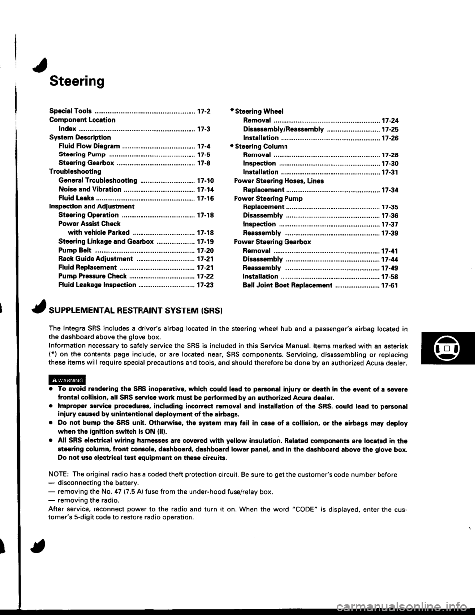
Steering
Componsnt Location
lndox
*Stooring Wheel
Removal ....
Disassombly/Ro8$.mbly
Disassombly ......
F08$€mbly
Powcr Stosring Gosrbox
R6moval
............................ 17-3
............. 17 -1
................ 17-16
............................. 17_25
17-30
17.31
.......17-21
Sy3tom DGcription
Fluid Flow Disgram
Steering Pump .............. 17-5
Stocring Goarbox ...17.8
Troublorhooting
Gonoral Troubleshooting .............................. 17.10
Noiso lnd Vibration ...... 17-1i[
Fluid Losk3
lnspoction
Installation
Powor Steering Hos6, Lino3
Roplacom€nt .................. 17.34
Powor Steoring Pump
RGplac6montlolpeqtion lnd Adiu3tm6nl
Stoo.ing Operation
Powor A$bi Chock
with v.hiclo Parked
Stcering Linkage 6nd Goarbox
Pump Bolt
17.18
17.18
17.19
17-20
17.35
t7-36
17 -37
r7-39
Inspoction
................... 17.41
Rack Guide Adiustmont ..........................-.-.-. 17 -21
Ffuid Rcplacemont ........17-21
Pump Prc&suro Chock ...,........................,..,..., 17 -22
Fluid Leakage Inrpection ............................... 17-23
Dissssembly
R€aEs€mbly
In3tallation........... 17_58
Ball Joint Boot Replacem.ni ........................ 17-61
17-U
17.49
J ,urrar*TNTAL REsrRArNr sysrEM (sRsr
The Integra SRS includes a driver's airbag located in the steering wheel hub and a passenger's airbag located inthe dashboard above the glove box,
Information necessary to safely service the SRS is included in this Service Manual. ltems marked with an asterisk(*) on the contents page include, or are located near, SRS components. Servicing, dissssembling or replacing
these items will require special pr6cautions and tools, and should therefore be done by an authorized Acura dealer.
. To avoid rondoring ths SRS inoparstivo. which could |rad to parsonal iniury or doath in the ov€nt of ! sev6.o
trontal collision, all SRS sarvice work must be perto.med by an authorizod Acura dsalor.. lmpropor 3orvic€ procadures, including inco[6ql rgmoval and inrtallation of the SRS, could l6ad to pgrsonal
iniury clus€d by unintentional doployment of the airbags,. Do nol bump tho SRS unh, (Xherwise, th6 3ystom may fail in cas€ ol a collision, or the airbags may d€ploy
when ths ignition switch is ON {ll).. All SRS electrical wiring harness€s aro covered with yallow insulation. Related component3 are located in ths
stcaring column. tront con3ol6, dashboard, d.shbolrd lower panel, and in the dashboard above ths glove box.
Do not u3o electrical test oquipm€nt on the3e circuii3.
NOTE: The original radio has a coded theft protection circuit. Be sure to get the customer's code number before- disconn€cting the battery.- removing the No. 47 (7.5 A) fuse from the under-hood fuse/relay box,- removing the radio.
After service, reconnect power to the radio and turn it on. When the word "CODE" is displayed. enter the cus-
tomer's 5-digit code to restore radio operation.
Page 651 of 1681

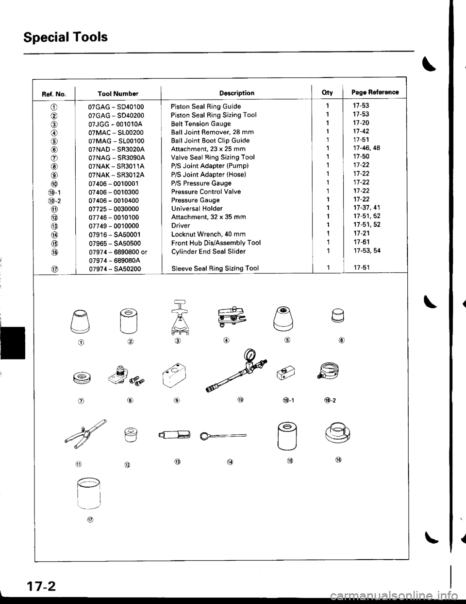
SpecialTools
{
\
\
17-2
Ref. No. I Tool NumberDsscriptionOty I Pags Reterenc.
o
@
@
o
@
@
@
@
@
@-1
@-2
o6:^
@
@
@
@
@
07GAG - SD40100
07GAG - SD40200
07JGG - 001010A
07MAC - S100200
07MAG - S100100
07NAD - SR3020A
OTNAG _ SR3OgOA
OTNAK - SR3O11A
OTNAK - SR3O12A
07406 - 0010001
07406 - 0010300
07406 - 0010400
07725 - 0030000
07746 - 0010100
07749 - 0010000
07916 - SA50001
07965 - SA50500
07974 - 6890800 or
07974 - 6890804
07974 - SA50200
Piston Seal Ring Guide
Piston Seal Ring Sizing Tool
Belt Tension Gauge
Ball Joint Remover, 28 mm
Ball Joint Boot Clip Guide
Attachment, 23 x 25 mm
Valve Seal Ring Sizing Tool
P/S Joint Adapter (Pump)
P/S Joint Adapter (Hose)
P/S Pressure Gauge
Pressure Control Valve
Pressure Gauge
Universal Holder
Attachment, 32 x 35 mm
Driver
Locknut Wrench. 40 mm
Front Hub Dis/Assembly Tool
Cylinder End Seal Slider
Sleeve Seal Ring Sizing Tool
'I
1
1
1
1'|
1,l
I
1
1
1'I
'l
1
1
1
1
1
't7-53
17-53't]-20
11-42
17 -51
17 -46, 4A
17-50
17-37, 41
11-51,52't1-51,52
17 -2'�1
17 -6'l
17-53. 54
17-51
o
L'4,
o
€)
-g)c-J 8p
@
@
6i
(9')\E/'
@-t
a
6
ffi
@-z
d--E ia*=-
o
l-l
t..-_-.r
A)
@@@
\
Page 652 of 1681

I
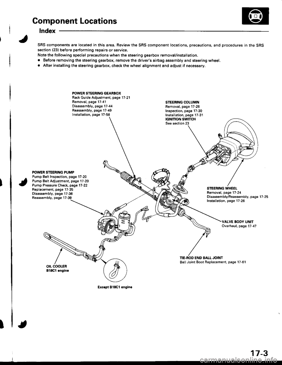
Component Locations
Index
SRS components are located in this area. Review the SRS component locations, precautions, and procedures in the SRSsection (23) before performing repairs or service.
Note the following special precautions when the steering gearbox removal/installation,
. Before removing the steering gearbox, remove the driver's airbag assembly and steering wheel.
. After installing the steering gearbox, ch6ck the wheel alignmentand adjust if necessary.
POWER STEERING GEARBOXRack Guid€ Adjustment, page 17 -21
Removal, pago 17-4'1Disassembly, page 17-44Reassombly. page'17-49Installation, page 17-58
STEEBING COLUMNRemoval. page 17-28Inspection, pago 17-30Installation, page 17-3'1|GNMON SWITCHSee section 23
POWER STEERING PUMPPump Belt Inspection. page 17-20Pump Belt Adjustment, page 17 -20
Pump Pr€ssuro Check, page 17'22Roplacament, page 17-35Dis686embly, page 17-36Reassembly, page 17-39
STEEBING WHEELRomoval, page 17-24Disassembf y/Reassembly, paga 17 -25
Installation, page 17-26
TIE.BOD END BALL JOINTBallJoint Boot Replacement, page 17-61
Exc.pt BlSCl onginc
17-3
Page 665 of 1681

Troubleshooting
Fluid Leaks
Check the gearbox assembly for oil leaks carefully, Oil can leak out of various points, depending on location of the
faulty oil seals/seal rings. Check the following before removing the gearbox from the frame.
Stoo.ing GearboxReplace the valv€ oil seal fromthe valvo houging.Leaking from the oil seal on thetop of the valve housing.
Roplace the valve oil seal fromthe pinion shaft.Leaking trom cylinder 6nd intol€ft ti6-rod boot,
B€place tho cylindgr ond seal onthe gear housing side.
Replaco th€ cylindor end seal onths cylinder end side.Leaking from cylinder end intoright tie-rod boot.
Leaking from the thaft upper endsection or pin ongagement sgc-tion ofth6 Dinion shaftRoDlace tho valve bodv unit.I
I
Tighten connector. lf it€ still leak-ing. replace th€ lin€, cylinder orvalve housing.
Leaking lrom cylind6r line A or Bconn6ction {Et flare nut).
Leaking caused by a damagedcylinder line A or B.Replace cylinder line A or B.
Tightgn tho connector. ll its stillleaking, r€place the hos€, joint
fitting or valv€ housing.
Leaking from outlet line andreturn line joint fitting on thevalv6 body unit (at flare nut).
17-16
Page 668 of 1681
I
Steering Linkage and Gearbox
STEERING COLUMNInspect tor loose columnmounting bolts and nuts.
TIE.ROD END BALL JOINTInspect tor faultv movementano oamage,
BOOTInspect lor damage and deterioration.
STEERING JOINTSCheck {or loose joint bolts.
PINION SHAFT GROMMETInsp6ct for damage and deterioration.
STEERING
TIE.ROD LOCKNUTCheck {or loose locknut.
Inspect for loose mounting bolts.GEARBOX MOUNTING CUSHIONSInspect for deterioration.
BALL JOINTInspect for damage and deterioration.See pago 17-61 lor replacement.
17-19