1998 HONDA INTEGRA ESP
[x] Cancel search: ESPPage 654 of 1681

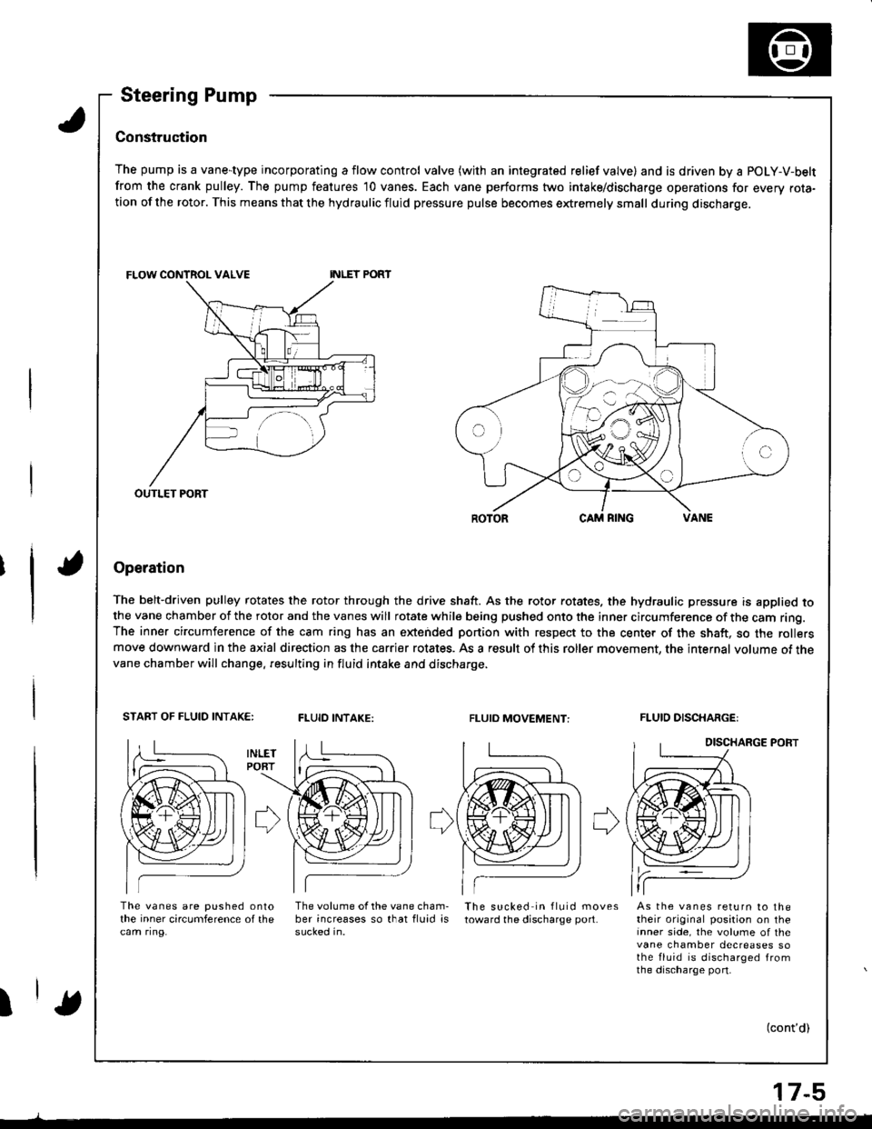
Steering Pump
Construc'tion
The pump is a vane-type incorporating a flow control valve (with an integrated relief valve) and is driven by a POLY-V-belt
from the crank pulley. The pump features 10 vanes. Each vane performs two intake/discharge operations for every rota-tion of the rotor. This means that the hydraulic fluid pressure pulse becomes extremely small during discharge.
Operation
The belt-driven pulley rotates the rotor through the drive shaft. As the rotor rotates. the hydraulic pressure is applied tothe vane chamber of the rotor and the vanes will rotate while being pushed onto the inner circumference of the cam ring.The inner circumference of the cam ring has an extended portion with respect to the center of the shaft, so the rollersmove downward in the axial direction as the carrier rotates. As a result of this roller movement, the internal volume of thevane chamber will change. resulting in fluid intake and discharge.
START OF FLUID INTAK€:FLUID INTAKE:FLUIO MOVEMENT:FLUID DISCHARGE:
DISCHARGE PORT
The vanes are pushed onlothe inner circumference of thecam ring.
The volume of the vane cham-ber increases so that fluid issucked in.
The sucked in fluid movestoward the discharge port.As the vanes return to thetheir original position on theinner side, the volume of thevane chamber decreases sothe fluid is discharged fromthe discharge port-
I(cont'd)
OUTLET PORT
17-5
Page 657 of 1681

System DescriPtion
Steering Gearbox
it
The rack,and-pinion type steering gearbox has a Valve body unit incorporated with the pinion to control the steering fluid
pressure. steering fluid from the pump is regulated by a rotary valve in the valve body unit and is sent through the cylin-
derpipetothepowercy|inder,wherehydrauIicpressureisapp|ied.Thesteeringf|Uidintheothersideofthepowercy|in-
der returns through the cylinder pipe and valve body unit to the reservoir'
Valve Body Unit
Inside the valve body unit is the valve, which is coaxial with the pinion shaft, and controls the steering fluid pressure The
valve housing ls connected wirh the fluid pipe from the pump. return pipe to the reservoir, and the two cylinder pipes
from the respective power cylinder.
The pinion shaft is double - structured with the input shaft connected to the pinion gear, both of which are interconnected
with the torsion bar.
The pin inserted in the valve and the pinion shaft groove engage; this allows the pinion shaft to rotate together with the
Because of this construction. the difference in angle in the circumferential direction between the input shaft and the valve
becomes larger according ro the torsional strength ol the pinion or steering resistance. However. maximum torsion
between the shafts is regulated by the engaged splines of the shafts at the pin engagement section to hold the torsion bar
within the set value.
This allows the steering system to function as an ordinary rack-and-pinion type steering if the steering iluid is not pressur-
ized because of a faulty PumP.
VALVE
INPUT SHAFT
INPUT SHAFT
VALVE XOUSING
of
'I
lEng.ge with th€ Pinionshaft groove)
TORSION BARDift6rance in angle b6twe€n theinput ih.ft.nd pinion shalt
la-l
B
VALVE BODY UN]T
SECNON B.B
17-8
Page 659 of 1681

Troubleshooting
General Troubleshooting
Check the following before you begin:
o Has the suspension been modified in a way that would affect steering?
. Are tire sizes and air pressure correct?
. lsthe steering wheel original equipment or equivalent?
. ls the power steering pump belt properly adiusted?
. ls steering fluid reservoirtilled to proper level?
. ls the engine idle speed correct and steadyT
Hard steering (check the power assist, see page 17-18. It the torce is over 34 N (3.5 kgf, 7 7 lbf), proceed with this troubl*hooting l
Abnormalfluidpressur€ (lluid
pressure rs roohish)
Too low reliefpress{ire
Normal line and hos6
I
II
iFaulty valve body unit
Normal Abnormal
rlrl
l{
Faulty pump assembly Faulty tlow control valv6
Ch€ck the tegd and return circuit lines and hoso
between the gearbox and pump for clogging and
detormation.
Check pump fluid Pressuro {sespage 17'221.Mgasure stoady-stat€ fluid Pres_sure while idling with the both
valv6Iully opon.It should be 1,500 kPa (15 kgf/
cm,,213 psi) or below.
Normal
Check the flow control valve (seo page 17-37).. Check the valvs Ior smooth movemont in the hous-
Ing.. Check tho reliel valvo for leaks.
Measure pump reliet prgssure
while idling with the both vslveIully closed.It should b€ 6,400 - 7,400 kPa {65- 75 kgt/cm'�, 924 - 1,067 psi)
Normal reliel pressure
I
I
+
Go to pags 17-11
17-10
Page 683 of 1681

Power Steering Hoses, Lines
Replacement
NOTE:
. Connect each hose to the corresponding line securely
until it contacts the stop on the line. Install the clamp
or adjustable clamp at the specified distance from the
hose end as shown.
. Add the recommended power steering fluid to the
specified level on the reservoir and check for leaks.
ADJUSTABLE HOSE CLAMP: (al
. Position the adjustable hose clamps at the points
indicated by (a) in the drawing below.
. Slide the hose over the line until it contacts the stop.
CAUTION: Ch€ck all clamps for deterioration or defor-
mation; replace the clamps with new ones it necessary'
HOSE CLAMP: (b)
. Position the hose clamps at the points indicated by
(b) in the drawing below.
. Slide the hose over the line until itcontactsthe stop.
2.5 - 5.5 mm(0.01 - 0.22 in)
RETURN LINE JOINT28 N m 12.9 kg{'m,2'l lbf'ft|
PUMP OUTLET HOSE(High'pressure)
37 N.m (3.8 kgtm,27 lbf.ft)
2.5-5.5 mm
10.01 - 0.22 in)2.0 - {.0 mm
10.08 - 0.16 inl
CYLINDER LINES17 N.m (1.7 kgt m, 12 lbf'ft)
PUMPOUTI.IT HOSE(High-pressure)
11 N.m11.1 kgl.m,8lbJftl
PUMPINLET HOSE(Low-pressurel
RETURN HOSE
Exc.pt Bl8Cl engino
17-34
Page 700 of 1681

12.Apply power steering fluid to the surface of the spe-
cial tool. Set the new seal rings over the special tool
from the smaller diameter end of the tool, and
expand the seal rings. Do two rings at a time from
each end of the sleeve.
NOTE:
. Do not over-expand the seal ring. Install the resin
seal rings with care so as not to damage them.
After installation, be sure to contract the seal
rings using the specialtool (sizing tool).
. There are two types of sleeve seal rings: black
and brown. Oo not mix the different types of
sleeve seal rings as they are not compstible.
Align the special toolwith each groove in the sleeve.
and slide a sleeve seal ring into each groove.
NOTE: After installation, compress the seal rings
with your fingers temporarily.
BALL JOINT B(X)? CUP GUIDE07MAG - SLdrlrx,
Apply power steering fluid to the seal rings on the
sleeve and to the entire inside surface of the soecial
tool.
SLEEVE SEAL NINGSIZING TOOL0r9?a - sat02n0
Insert the sleeve into the special tool slowly.
Move the sleeve each direction several times to
make the seal rings snugly fit in the sleeve.
NOTE: Be sure that the seal ringsare notturned up.
13.
14.
to.
17-51
Cutout.
17.Apply power steering fluid to the surface of the pin-
ion shaft, assemble the sleeve over the pinion shaft
by aligning the locating pin on the inside of the
sleeve with the cutout in the shaft. Then install the
new circlip securely in the pinion shaft groove.
NOTE:
. Be careful not to damage the valve seal ring
when inserting the sleeve.
. Install the circlip with its radiused side facing in,
18. Installthe circlip securely in the pinion shaft groove.
Apply power steering fluid to the seal ring lip of the
valve oil seal. Then install the seal in the valve
housing using a hydraulic press and special tools as
snown.
CAUnON: Instsll tho valvo oil s€.| with its groovcs
side facing th. tool.
19.
ATTACHMET{T,32x35mm077i15 - (xll01lX,
VALVE OIL SEALReplace.Make sure thespring in theoilseal.
(cont'd)
Page 779 of 1681

IABS Control
The ABS control unit detects the wheel speed based on the wheel sensor signal it received, then it calculates the vehiclespeed based on the detected wheel speed. The control unit detects the vehicle speed during deceleration based on therate of deceleration.
The ABS control unit calculates the slip rate of each wheel, and it transmits the control signal to the modulator unitsolenoid valve when the slip rate is high.
The pressure reduction control has three-modes: pressure reduction, pressure retaining, and pressure intensifying.
Self-diagnosis Function
The CPUS in the ABS control unit check the circuit of the system.
The self-diagnosis can be classifield into two categories.. Initial diagnosis: Performed right after the engine starts and until the ABS indicator gose off.. Regular diagnosis: Performed right after the initial diagnosis until the ignition switch isturnedoff.
On-board Diagnosis Function
The ABS control unit is connected to the data link connector fi6p).The ABS system can be diagnosed with the Honda PGM Tester.
(cont'd)
19-27
Page 877 of 1681

Rear Window
{
lnstallation
2.
3.
Scrape the old adhesive smooth with a knife to a
thickness of about 2 mm {O.08 in) on the bonding
surface around the entire rear window opening
tlange.
NOTE:
a Do not scrape down to the painted surface of the
body; damaged paint will interlere with proper
bonding.
a Remove the upper and lower fasteners trom the
hatc n.
a Mask oft surrounding surfaces belore applying
primer.
Clean the hatch bonding surface with a sponge
dampened in alcohol.
NOTEr After cleaning, keep oil, grease or water from
getting on the surface.
lf the old rear window is to be reinstalled, use a put-
ty knite to scrape off alltraces of old adhesive, then
clean the rear window surlace with alcohol where
new adhesive is to be applied.
NOTE: Make sure the bonding surface is kept free
of water, oil and grease.
CAUTION: Avoid setling ths rear window on its
edges; the molding can be permanently detormed.
NOTE: Clean the shadowed area.
REAfi WINDOW
20-62
Apply the upper seal to the inside face of glass as
shown.
Glue the upper fasteners, lower lasteners and side
spacers, to the inside face of the rear window on
each side.
UPPER SEAL
MOLDING
5.
ALIGNMENTMARK
REAR DEFOGGERTEEMINAL
C> locaiion:
ALIGNMENTMARKSUPPER
ALIGNMENTMARKSALIGNMENTMARKS
;>t";",i".",
)
SIDESPACER,2
6.Glue the lower lasteners and uooer {asteners to the
hatch as shown.
a > i*"ri".* -\
LOWERFASTENERS, 2I
'N^ |
ALIGNMENTMARKSMARKS
UPPER SEAL
Page 1061 of 1681

Troubleshooting
Tips and Precautions (cont'd)
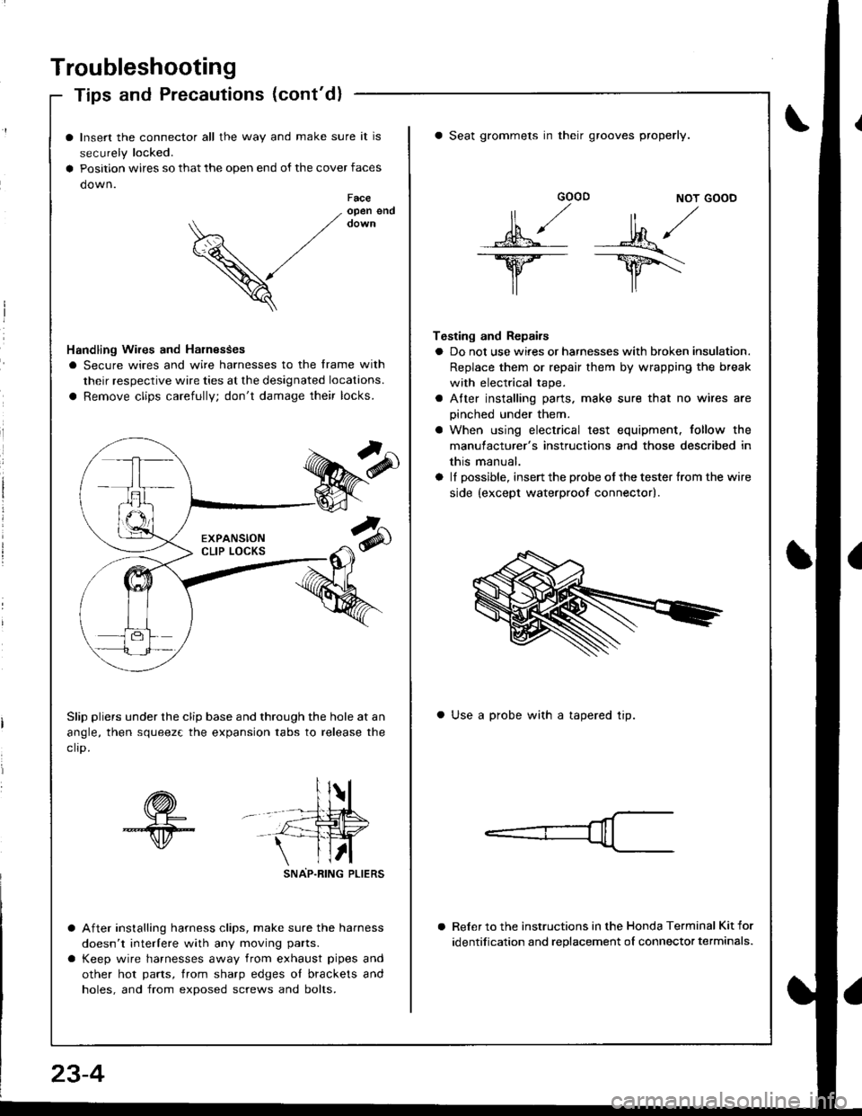
Insert the connector all the way and make sure it is
securely locked.
Position wires so that the open end of the cover faces
down.Faceopen end
V
Handling Wires and Harnesses
I Secure wires and wire harnesses to the frame with
their respective wire ties at the designated locations.
a Remove clips carefully; don't damage their locks.
Slip pliers under the clip base and through the hole at an
angle, then squeez€ the expansion tabs to release the
clro.
sNAP-R|NG PLtERS
After installing harness clips, make sure the harness
doesn't interlere with any moving parts.
Keep wire harnesses away from exhaust pipes and
other hot parts, trom sharp edges ol brackets and
holes, and from exposed screws and bolts.
GOOD NOT GOOD
MA/
lr lr\
Testing and Repairs
a Do not use wires or harnesses with broken insulation.
Replace them or repair them by wrapping the break
with electrical tape.
a Atter installing parts. make sure that no wires are
oinched under them.
a When using electrical test equipment. follow the
manulacturer's instructions and those described in
this manual.
a lI possible, insert the probe of the tester {rom the wire
side {except waterproot connector).
a Seat grommets in their grooves properly.
a Use a probe with a tapered tip.
Reler to the instructions in the Honda Terminal Kit for
identification and replacement oI connector terminals.
23-4