Page 1144 of 1681

J
Starting System
Performance Test
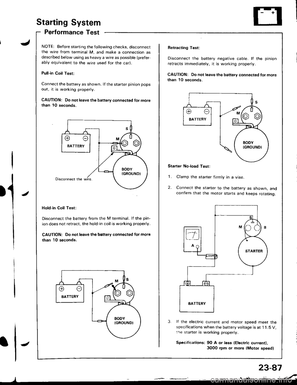
NOTE: Before starting the following checks, disconnectthe wire from terminal M, and make a connection asdescribed below using as heavy a wire as possible (prefer
ably equivalent to the wire used for the car).
Pull-in Coil Test:
Connect the battery as shown. If the starter pinion pops
out, it is working properly.
CAUTION: Do not leave the battery connectsd Jor morethan 1O seconds.
Hold-in Coil Test:
Disconnect the battery from the M terminal. lf the pin-
ion does not retract, the hold-in coil is working properly.
CAUTION: Do not leave the battery connected for more
than 10 seconds.
J
Retracting Test:
Disconnect the battery negative cable. lf the pinion
retracts immediately, it is working properly.
CAUTION: Do not leave the battery connected fol more
than 1O seconds.
Starter No]oad Test:
1. Clamp the starter firmly in a vise.
2. Connect the starter to the battery as shown, andconfirm that the motor starts and keeps rotating.
3 lf the electric current and motor soeed meet thespecifications when the battery voltage is at 1 1.5 V,the starter is working properly.
Sp€cifications: 9O A or less (Electric currentl,
3O0O rpm or more {Motor speed}
Page 1153 of 1681

lgnitionSystem
Coil TestlgnitionlgnitionCoilReplacement
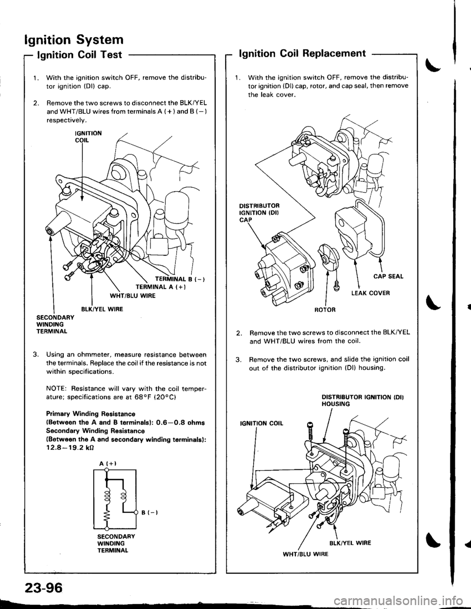
1. With the ignition switch OFF, remove the distribu-
tor ignition (Dl) cap, rotor, and cap seal, then remove
the leak cover.
Remove the two screws to disconnect the BLK/YEL
and WHT/BLU wires lrom the coil.
Remove the two screws, and slide the ignition coil
out of the distributor ignition (Dl) housing.
DISTRIBUTOR IGNITION {DIIHOUSING
ROTOR
WHT/BLU WIRE
2.
1.With the ignition switch OFF, remove the distribu-
tor ignition (Dl) cap.
Remove the two screws to disconnect the BLK/YEL
and WHT/BLU wi.es from terminals A ( + ) and B {- )
respectively.
SECONDARYWINDINGTERMINAL
3. Using an ohmmeter, measure resistance between
the terminals. ReDlace the coilif the resistance is not
within soecifications.
NOTE: Resistance will vary with the coil temper-
ature; specifications are at 68oF (20oC)
Plimary Winding Rssistance(Between th€ A 8nd B torminalsl: 0.6-O,8 ohms
Socondary Winding Resistance(Betwe€n the A and secondary winding torminalsl:
12.4-19.2 kA
B (-t
SECONDARYWllrlDlNGTENMINAL
TERMINAL A (+I
A {+}
{
t
l
tl
t9
t
L--
23-96
Page 1178 of 1681
Gauge/lndicator/Terminal Location Index
coNNECTOR "8" (C5601
ltrii
rll
coNNECTOR "C" (Css8l
ACHOMETER:rdicates 10O rpm al
OO pulses per minutef the ignition controlrodule {lCM).
81 ------------ 816
ililllllilll
A,/T GEAR POS]TIONINDICATOR SYSTEMS€e page 23-140
c1 ------>cl0
I
Jilliltl
atespage 23-131t Test, page 23-132
^a1(
u;" u
7' /'- /n.u (,w.--
" oe)\r- -7 ttt'-1 r --
I 'l I z{.-a\y' | \-./^l
!t tr--',9I I l\-//11, I t,-\Jl
.r' to"-ei
I :rl
F<
elrle
ENGINE COOLANT TEMPERATUREGauge T€st, page 23-134Sending Unit Test, page 23'134
IECTI GAUGE:
A1 ----> A5
D1-------->D13
ililtl|illl
SPEEOOMETER:lndicates (60 mph at 1025 rpm) or
{60 km/h at 637 rpm) of the
vehicle speed sensor {VSS).
coNNECTOR "A" (C557)
coNNECTOR "D" (C5591
23-121
Page 1389 of 1681

How To Use This Manual
Component Locations
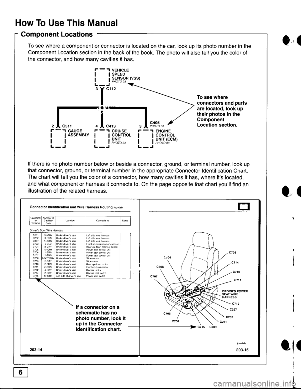
To see where a component or connector is located on the car, look up its photo number in the
Component Location section in the back of the book. The photo will also tell you the color of
the connector. and how manv cavities it has.
VEHICLESPEEDSENSOR (VSS)
ENGINECONTROLUNIT (ECMPHOIO 8A
0,, I
tl
tl
'r"'
To see where
connectors and parts
are located, look up
their photos in the
Component
Location section.
r -.I GAUGE
| | ASSEMBLY I
rtlL-J L-
r -'l
ll
ll
O,(
ot(
il"l,*.I CRUISE
I CoNTROL
i"u,t',:..
lf there is no photo number below or beside a connector, ground, or terminal number, look up
that connector, ground, or terminal number in the appropriate Connector ldentification Chart.
The chart will tell you the color of a connector, how many cavities it has, where it's located,
and what component or harness it connects to. On the page opposite that chart you'll find an
illustration of the related harness.
Connector ld6nlillcallon and Wire Harness Rouling tconrd)
SEAT WIFEHAFNESS
c712lf a connector on a
schematic has no
photo number, look it
up in the Connector
ldentification chart.
c297
203-15203-14
t-
Page 1419 of 1681
TRANSMISSION
I
I
T4
PGM-FIMAIN RELAYPage 23 ('98-'99)or 24 ( 00)
tl
tlL-J
* : '98-'99 Models
i---------\L---------J(- 10) r-- -;-;.11, (c408.)(- 23)10
'98- 99.. GS.R' l/odel
inrrarerrn i
I
I
.-- GS-R. TYPE.R
VEHICLESPEEDSENSORRADIATOBFAN SWITCH
and 63 2
tl
tlL-Jcl08
(vss)Page
PHATO 6IIITJ
I
I
33
I
I
c3o1 ;
10
Ground Distribution
NOTE: Wires shown without color codes are black.
VALVECOVER
I
I
- G1, G2, G3, and G101
I
I
T3
BATTERYPage 10
r-'r
tl
ll'n'
I
I
I
I
I*-*rl
I
I
I
I
! F,to,o^_l1io,o,o *
14
Page 1451 of 1681
Vehicle Speed Sensor (VSS)
FUSE 15
.t UNDER.DASH
! SBiE/RELAY
'--- 98 99 models with A,rT ----
1
5
J^r""'See Groundarr< Diskibulion,
I o"o" t+
"'*l I
!r::'-'
c438
".,,::.x
POWERTRAIN '| ,,--,^,- | or ENGINEI l:li.:" a coNrRoLi ::J:" : MODULE :
i
'{is,
i!""""9;li"S, j
L---J pHaral&(oo)
ll
Vehiclespeedinput
c30t
CRUISECONTROLUNITtl
! y::g" II i,ifi- |L---J
-ir""'
MAINTENANCEREMINDERUNIT
(98-'9918) y. C409
c452
12
I BLK/. YEL
, BLK/I YEL
BLK'YEL
-'oomodel GS'R-----.
See Powera4 Distribution,
I
ease 1o-3.
x-----
l
c127
c1't2VEHICLESPEEOSENSOF(vss)PHOfO 26
lgnitioninputVehiclespoed output
Ground
33
Page 1457 of 1681

Cruise Control (cont'd)
- How the Circuit Works
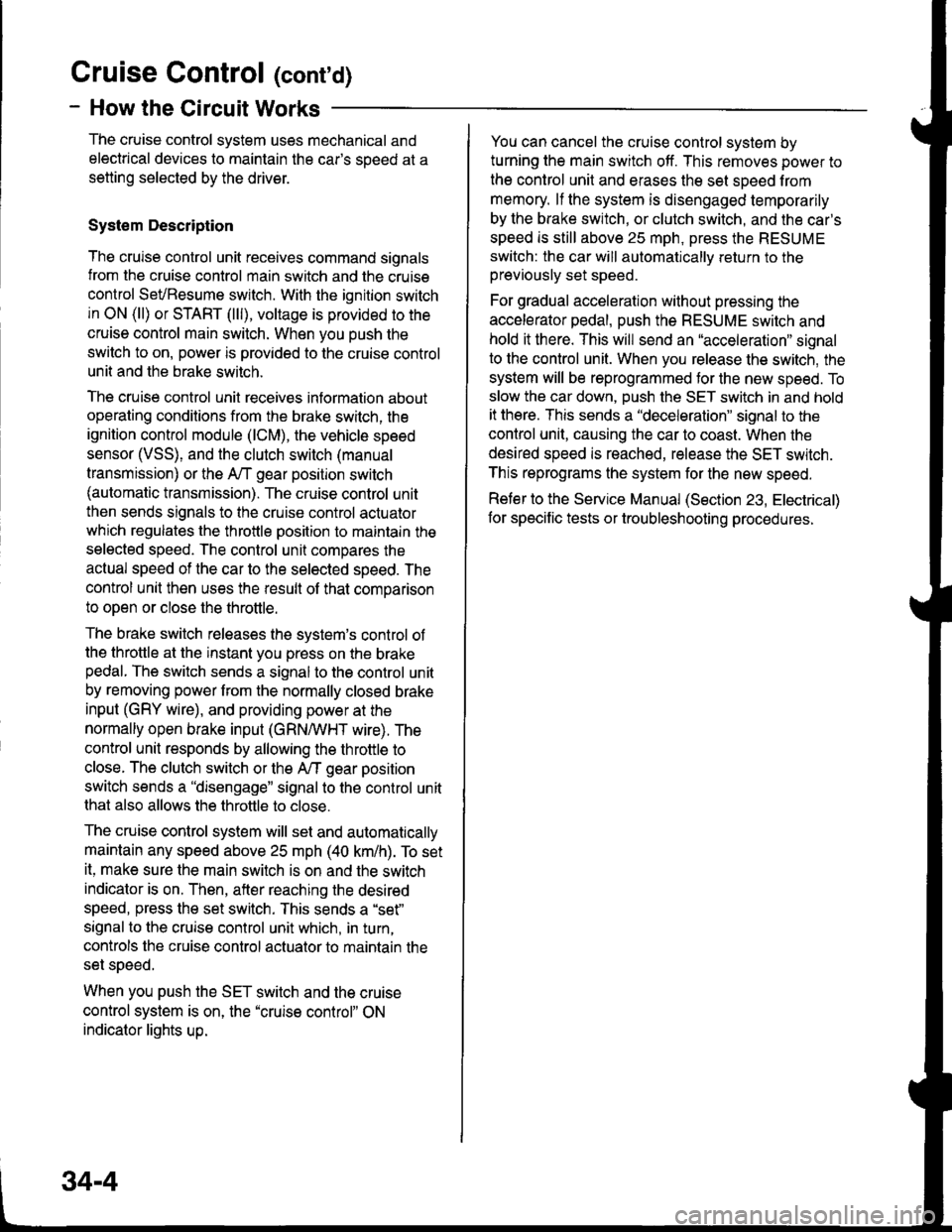
The cruise control system uses mechanical and
electrical devices to maintain the car's soeed at a
setting selected by the driver.
System Description
The cruise control unit receives command signals
from the cruise control main switch and the cruise
control SevBesume switch. With the ignition switch
in ON (ll) or START (lll), voltage is provided to the
cruise control main switch. When you push the
switch to on, power is provided to the cruise control
unit and the brake switch.
The cruise control unit receives information about
operating conditions from the brake switch, the
ignition control module (lCM), the vehicle speed
sensor (VSS), and the clutch switch (manual
transmission) or the A,/T gear positton switch
(automatic transmission). The cruise control unit
then sends signals to the cruise conirol actuator
which regulates the throttle position to maintain the
selected speed. The control unit compares the
aclual speed of the car to the selected speed. The
control unit then uses the result of that comoarison
to oDen or close the throttle.
The brake switch releases the system's control of
the throttle at the instant you press on the brakepedal. The switch sends a signal to the control unit
by removing power from the normally closed brake
input (GRY wire), and providing power at the
normally open brake input (GRNMHT wire). The
control unit responds by allowing the throttle to
close. The clutch switch or the A/T gear position
switch sends a "disengage" signal to the control unit
that also allows the throttle to close.
The cruise control system will set and automatically
maintain any speed above 25 mph (40 km/h). To set
it, make sure the main switch is on and the switch
indicator is on. Then, after reaching the desired
speed, press the set switch. This sends a "set"
signal to the cruise control unit which, in turn,
controls the cruise control actuator to maintain the
set soeed.
When you push the SET switch and the cruise
control system is on, the "cruise control" ON
indicator lights up.
34-4
You can cancel the cruise control system by
turning the main switch off. This removes power to
the control unit and erases the set sDeed from
memory. lf the system is disengaged temporarily
by the brake switch, or clutch switch, and the car's
speed is still above 25 mph, press the RESUME
switch: the car will automatically return to the
previously set speed.
For gradual acceleration without pressing the
accelerator pedal, push the RESUME switch and
hold it there. This will send an "acceleration" signal
to the control unit. When you release the switch, the
system will be reprogrammed tor the new speed. To
slow the car down, push the SET switch in and hold
it there. This sends a "deceleration" signal to the
control unit, causing the car to coast. When the
desired speed is reached, release the SET switch.
This reprograms the system for the new speed.
Reter to the Service Manual (Section 23, Electrical)
for specific tests or troubleshooting procedures.
Page 1501 of 1681
Maintenance Reminder Light
i-T;;-l
t-IY--i
,"",,":lt*'
i
UNDER.HOODFUSE/RELAYBOX
aaa4
""rr"a"
I
:'^.:tr'--'
!aaE�+
"-",l_
Sse Pows.Distribulionpsge l0{.
Ssg PowsrDisribr.rtlonpage iGS.
MAINTENANCEREMINDERUNIT
F
;ilr
""'
a
onr I
F:"?l F"x%''�
arr-<
"T
I'*""T
I "',,
"--:i:;;"
r-.=-l vEHlcLEI venrcle I SPEEDI speed ! SENSORI outpur | rySS)L__J PHaro 26
See VehicleSpeed Sensor(vss)
lgnitionlnp{.rtMaintenancer€mnoarlight conlrol
GfoundVehicle spe€dinput
83