Page 1313 of 1681

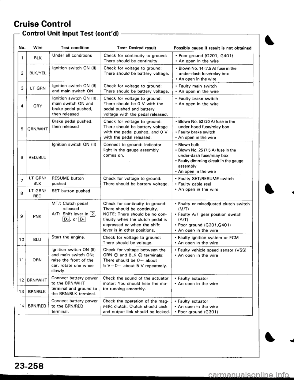
Cruise Control
- Control Unit InputTest(cont'dl
IBLKUnder all conditionsCheck for continuity to ground:
There should be continuity.
. Poor ground (G20l, G401). An open in the wire
2BLK/YEL
lgnition switch ON {ll}Check for voltage to ground:
There should be battery voltage.
. Blown No. l4 (7.5 Alfuse in the
under-dash fuse/relay box. An open in the wire
3LT GRNlgnition switch ON (ll)
and main switch ON
Check for voltage to ground:
There should be battery voltage.
. Faulty main swjtch. An open in the wire
GRY
lgnition switch ON (ll),
main switch ON and
brake pedal pushed,
then released
Check for voltage to ground:
There should be O V with the
pedal pushed and battery
voltage with the pedal released.
. Faulty brake switch. An open in the wire
5GRN/WHT
Brake pedal pushed,
then released
Check for voltage to ground:
There should be battery voltage
with the pedal pushed, and 0 V
with the pedal released.
Blown No. 52 (20 A)fuse in the
under-hood fuse/relay box
Faulty brake switch
An open in the wire
6RED/BLU
lgnition switch ON (ll)Connect to ground: lndicator
light in the gauge assembly
comes on.
Blown bulb
Blown No. 25 (7.5 A)fuse in the
under-dash fuse/relay box
Faulty dimming circuit in the gauge
assembly
An open in the wire
7LT GRN/
BLK
RESUME button
pushed
Check tor voltage to ground:
There should be battery voltage.
Faulty SET/RESUME switch
Faulty cable reel
An open in the wire8LT GRN/
RED
SET button pushed
IPNK
MT/: Clutch pedal
released
A/Tr Shift lever in [2l,
[Dl]. o, [o'l
-
Check for continuity to ground:
There should be continuity.
NOTE: There should be no con-
tinuity when the clutch pedal is
depressed or when the shift
lever is in other positions.
Faulty or misadjusted clutch switch(M/T)
Faulty A/T gear position switch(A/T)
Poor ground (G201,G401)
An open in the wire
't0BLUStart the engine.Check lor voltage to ground:
There should be voltage.
. Faulty ignition system or ECM. An open in the wire
't1ORN
lgnition switch ON (ll)
and main switch ON;
raase the front of the
car, rotate one wheel
slowly.
Check for voltage between the
ORN @ and BLK O terminals:
There should be 0- about
5 V-O- about 5 V repeatedly.
. Faulty vehicle speed sensor {VSS). An open in the wire
BRN/WHTConnect battery power
to the BRN/WHT
terminal and ground to
the BRN/BLK terminal.
Check the sound of the actuator
motor: You should hear the mo-
tor running smoothly.
. Faulty actuator. An open in the wire
BRNi BLK
Connect battery power
to the BRN/RED
Iermrnal.
Check the operation of the mag-
netic clutch: Clutch should click
and output link should be locked.
Faulty actuator
An open in the wire
Poor ground (G30'l)
No. Wire Test conditionTest: Desiled result Possible cause il lesult is not obtained
' 4 I BRN/RED
{
{
23-258
-L
Page 1320 of 1681
)
Wipers/Washers
Component Locationlndex
WINDSHIELD/BEAR WINDOWWIPER/WASHER SWITCHTest, page 23-269Replacement. page 23-268
wlNOSHIELD WIPERARMS/BLADESReplac6ment, page23-272
WINDSHIELDWIPER MOTORTest, page 23 271Replacement. page 23-272
WINDSHIELD WASHERMOTORfest. page 23-27 4
REAR WINDOWWASHER MOTORTest, page 23-2"14UNDER.DASHFUSE/RELAY BOX
INTERMTNEMT WIPERFELAY CIRCUN(ln the integrated control unit)Inpur Test, page 23-154
I
ul!
REAR WINDOW WIPER MOTORTest, page 23-273
23-265
Page 1321 of 1681
(
Wipers/Washers
Circuit Diagram
UNDEF.OASHFUSEiRELAYSOX
NTE NMI]TEI'IIWPES RELAYCIFCUIT/ In lhe inr6grar6d \ @nlrolun( I
IGNITIONSW TCHUNDER,HOOD FUSE/RELAY BOX
GRI]/BLK
GFIVBLK
WINDSHIELO WPENJWASHER SWITCH
BLK
G201G401
* : Wilh combined washer-wiDer ooeralion
BLI(GRN
I
A w'',,os"( M ) WASHER
Y
MoroF
8LK
I
G301
23-266
I
Page 1332 of 1681
!
Gomponent/Wiring Locations Index
SRS INDICATOR LIGHT(ln the gauge assembly)Troubleshooting, page 23-287Gauge assembly, page 23-126
To HORN SWITCH
CABLE REELReplacement,page 23-322
DRIVER'S AIRBAGReplacement. page 23-317Disposal, page 23-320To DRIVER'S AIRBAG
DASHBOARD WIRE HARNESSFRONT PASSENGER'SAIRBAGBeplacement, page 23-317Disposal, page 23-320
to SRS INDICATOR LIGHT in GAUGE ASSEMBLY5P CONNECTOR
SRS MAIN HARNESSTo MAINWIRE HARNESS3P CONNECTOR
SRS MAINHARNESSto UNDER-DASHFUSE/RELAYBOX2P CONNECTOR
HARNESSto FRONT PASSENGERS AIRBAG2P CONNECTOR
SRS MAIN
SERVICE CHECXCONNECTOR {2PIIBRNAAIHT, BLK]to CABLE REEL2P CONNECTOR
MAIN WIRE HARNESSto DASHBOARD WIREHARNESS16P CONNECTOR
ERASE SIGNAL (MES}SRS UNITGBOUNOSRS MAIN HARNESSSRS UNIT(lncluding safing sensorano rmpact sensor)R6placement, page 23-326
2P CONNECTORSRS MAIN HARNESSto SRS UNIT18P CONNECTOR
S\--0
[GRN, GRNI or IWHT, BLKI
23-27A
Page 1333 of 1681

Description
I
J)
)
'\' '\, ili \.-.-1 i^\\,,; i \
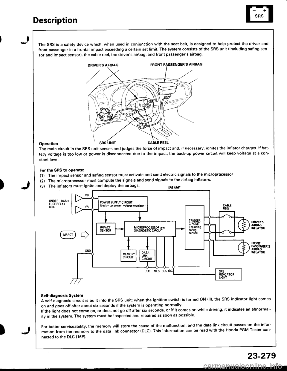
The SRS is a safetv device which, when used in coniunction with the seat belt, is designed to help protect the driver and
front passenger in a frontal impact exceeding a cenain set limit. The system consists ot the SRS unit (including safing sen-
sor and imDact sensor), the cable reel, the driver's airbag, and front passenger's airbag
Operation t'Its
The main circuit in the SRS unit senses and judges the force ot impact and, il necessary, ignites the inflator charges. If bat-
tery voltage is too low or power is disconnected due to the impact, the back-up power circuii will keep voltage at a con-
stant level.
For the SRS to operate:
(1) The impact sensor and safing sensor must activate and send electric signals to lhe mictop.Goi
{2) The microprocessor must compute the signals and send signals to the airbag inflators'
(3) The inflators must ignite and deploy the airbags sE Lr.r
UNDER DASHFUSE/RELAYBOX
Dnftr sAtacranroq
IIMPACT I ] )
F80t{TPASSEI{GEffSAIRSAGINFLAIOR
Drc MES SCS rDC
Self-diagnosis System
A self-diagnosis circuit is built into the sRs unit; when the ignition switch is turned oN (ll), the sRS indicator light comes
on and goes off after about six seconds if the system is operating normally'
lf the light does not come on, or does not go off after six seconds, or if it comes on while driving. it indicates an abnormal-
ity in the system. The system must be inspected and repaired as soon as possible'
For better servicesbility. the memory will store the cause of the malfunction, and the data link circuit passes on the infor-
mation from the memory to the data link connector (DLC). This information can be read with the Honda PGM Tester con-
nected to the DLc (16P).
23-279
J
Page 1334 of 1681
Circuit Diagram
FRONTPASSENGEF'SAJRBAGINFLATOR
f\4r
tlGRN GRN(YEL) (BLi.,'YEL)
I
G701
IGNITIONswtTcH
SRS INOICATOF CIBCUIT(ln the gauge assembly)
8LU
I
I
siEi'
IGRN
GRN(8RN)
I?
RNAVHT BRII/WHTlltl\---7 \*7
ECM SERVICECHECKcoirNEcTon
WHT/BLK +WHT
t"'
DATA LINKCONNECTOF(DLC)(r6P)
UNDEF-DASHFUSURELAY80x
ELKRED
J
PGM-FImain r€lay
MEIiIORY ERASEr2pt SIGNAL (MESIcoNNECToR (2P)
SRS UNIT TERMJNALS
BLX
G201G401
-NOER.NOOD FUSE/RELAY BOX
SRS INDICATORLIGHT 0.4W)
10 14 1 13 6 7(VA) 3(VB)SRS UNIT16 17 15 9188
DRIVER'SAJFBAGINFLATOR
1367I
10,/1,/1314151718
lerminal sde o{ male tefinnals
23-280
\'
Page 1346 of 1681
Troubleshooting
SRS Indicator Light Wire Connections
SRS Indicator Light Power Circuit
To UNDER-DASHFUSE/RELAY BOX2OP CONNECTOB
SRS Indicator Light Control Circuit
To SBS UNIT
iI
SRS MAIN HABNESS
C55'1, C557 : WIRE SIDE OF FEMALE TERMINALS
DASHBOARD WIRE HARNESS
MAIN WIRE HARNESS
C557 -+ To GAUGE ASSEMBLY
CiP7, C449 : TERMINAL SIDE OF MALE TERMINALSC553, CEo1. C802, C804: WIBE SIDE OF FEMALE TEFMINALS
DASHBOAND WIREHARNESS
To UNOEF-DASHFUSE/RELAY BOX2P CONNECTOR
C427 : MAIN WIRE HARNESS 3P CONNECTORC/r49 : MAIN WIBE HARNESS 16P CONNECTORC551 : DASHSOARD WIRE HARNESS 2Op CONNECTORC553 : DASHBOARD WIFE HARNESS t6P CONNECTORCssT : OASHBOARD WlnE HABNESS SP CONNECTOB
To GAUGE ASSEMBLY
C801 : SRS MAIN HARNESS 2P CONNECTOBC802 : SRS MAIN HARNESS 3P CONNECTORC804: SRS MAIN HAFNESS 18P CONNECTOR
BLU
Page 1347 of 1681

The SRS Indicator Light Doesnt Come On
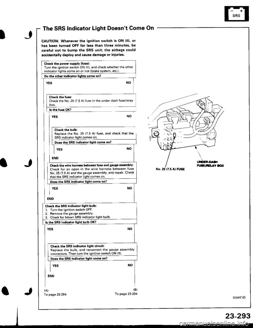
CAUTION: Whenever the ignition switch is ON (lll, ol
has been turned OFF tor lsss than three minutes. be
careful not to bump the SRS unit; the airbags could
accidentslly deploy and cause damage or iniuries.
Chcck tho power supply lfuso):Turn the ignition switch ON (ll), and check whether the other
indicator lights come on or not (brake system, etc.).
Do tho oth6J indicator ligh$ come on?
NO'ES
Check ths tuse:Check the No. 25 (7.5 Ai fuse in the under dash fuse/relayho!
ls th. tu.o OK?
YESNO
Chsck the bulb:Replace the No. 25 17.5 A) fuse, and check that the
SRS indicator light comes on.
Doos tho SRS indic.lor light como on?
YES
END
Ch.ck th6 wir€ ham€ls b€twoen fu3e snd gauge .3sembly:
Check for an open in the wire harness belween tuse
No. 25 (7.5 A) and the gauge sssembly, and repair. Check
that the sRS indicator light comes on.
Doo3 the SRS indicator light come on?
YES
NO
NO
END
Ch6ck tho SRS indicator light bulb:
1. Turn the ignition switch OFF.2. Remove the gauge assemblY3. Check tor blown SRS indicator light bulb.
b tho sRs indicrlor light bulb oK?
YESNO
Check tho SRS indicator ligln circuit:ReDlace the bulb, and reconnect the gauge assembly
connectors. Then turn the ignition switch ON (ll).
Do.s tho SRS indicrtor light comG on?
I vrs NoII
END
No. 25 lt.5 Al FUSE
{A)fo page 23-294
(B)
10 page 23-294(cont'd)