Page 1271 of 1681
Rear Window Defogger
Component Location Index
Description
The rear window de{ogger is controlled by the integrated control unit. Pushing the detogger switch in the Instrumentpanel sends a signal to the defogger timer in the integrated control unit, and the defogger stays on for 25 minutes oruntil the ignition switch is turned off. The indicator light in the switch comes on when the defogger works.
UNDER.OASH FUSE/RELAY BOX
r-'luijij u lNEAR WINDOWDEFOGGER SWITCHRemoval, page 23-217Test, page 23 217
REARDEFOGGERREI-AYTest, page 23-69
23-214
Page 1272 of 1681
Circuit Diagram
REARwtNDowDEFOGGERSWITCH
BLK
IIJ
DASH LIGHTSBR CHTNESSCONTROLLER
CN TIONswrTcH
/ 8AT \
T ",7-l
II
II
WNT/BLK + WHT
REARWiNDOWDEFOGGER
BtK/GRN
--lELKGRN BLI(RED
1A
T L-]
ll
tl
tl
tl-l
UNDEF HOOD FUSE/RELAY BOX
No41 (100A) N0.42 (40A)
G201G401G201G40lHatchback:G771Sedan iG503I
23-215
Page 1275 of 1681

Rear Window Defogger
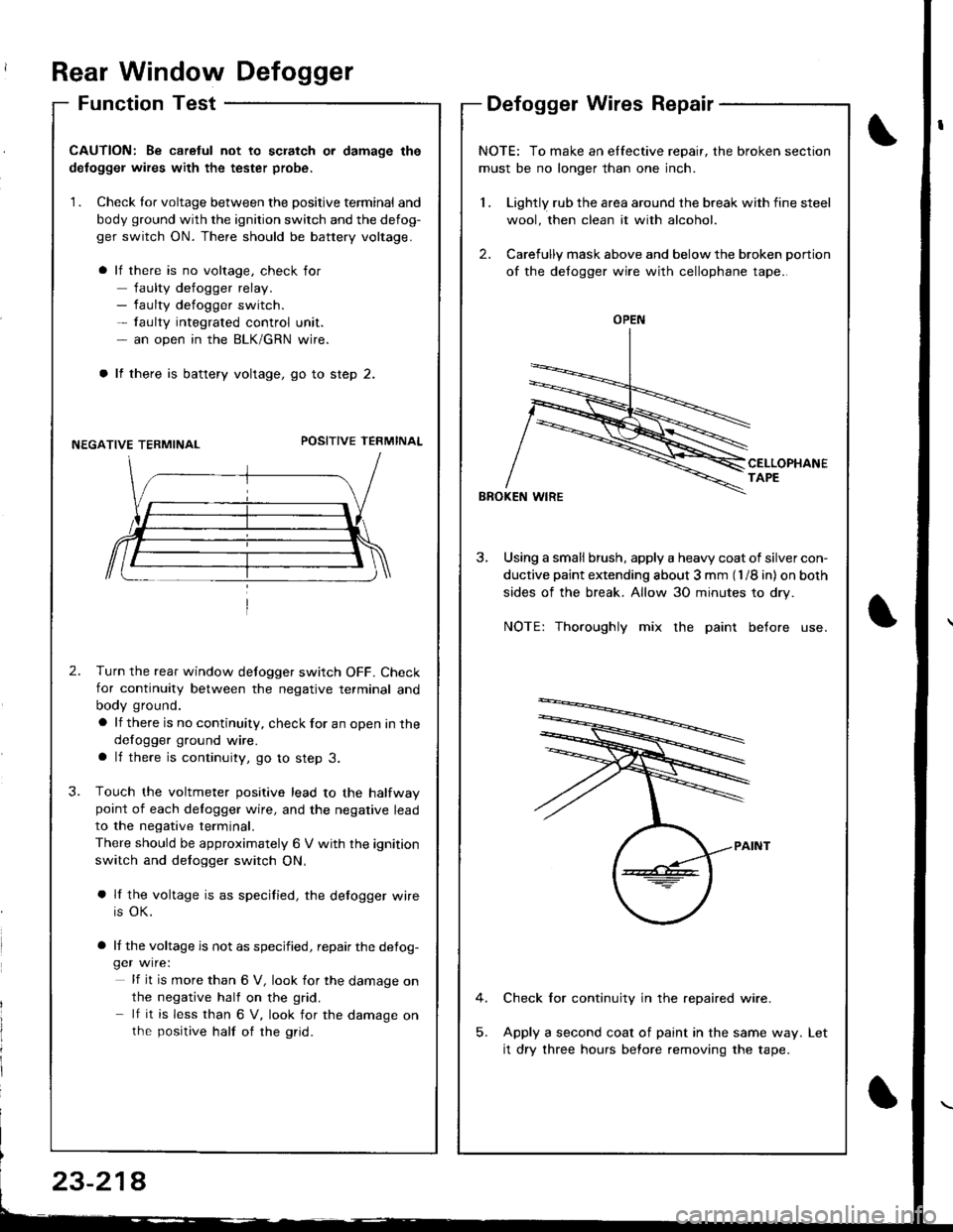
Function TestDefogger Wires Repair
I
I
CAUTION: Be caretul not to scratch or damage the
defogger wires with the tester probe,
1. Check tor voltage between the positive terminal and
body ground with the ignition switch and the defog-
ger switch ON. There should be battery voltage.
lf there is no voltage, check for
faulty defogger relay.- faulty defogger switch.- faulty integrated control unit.- an open in the BLK/GRN wire.
lf there is battery voltage, go to step 2.
NEGATIVE TERMINALPOSITIVE TEFMINAL
2.Turn the rear window defogger switch OFF. Check
for continuity between the negative terminal and
body ground.
a lf there is no continuity, check for an open in the
defogger ground wire.a lf there is continuity, go to step 3.
Touch the voltmeter positive lead to the halfwaypoint of each delogger wire, and the negative lead
to the negative terminal.
There should be approximately 6 V with the ignition
switch and defogger switch ON,
a lf the voltage is as specified, the defogger wire
is OK.
a lf the voltage is not as specified, repair the defog-ger wire:
lf it is more than 6 V, look for the damage on
the negative half on the grid.
lf it is less than 6 V, look for the damage onthe positive half of rhe grid.
3.
NOTE: To make an elfective repair, the broken section
must be no longer than one inch.
1 . Lightly rub the area around the break with fine steel
wool, then clean it with alcohol.
2. Carefully mask above and below the broken portion
of the defogger wire with cellophane tape.
CELLOPHANETAPE
BBOKEN WIRE
3, Using a small brush, apply a heavy coat of silver con-
ductive paint extending about 3 mm (l /8 in) on both
sides of the break. Allow 30 minutes to dry.
NOTE: Thoroughly mix the paint before use.
Check for continuity in the repaired wire.
Apply a second coat of paint in the same way.
it dry three hours before removing the tape.
Let
OPEN
23-214
Page 1277 of 1681
Moonroof
Circuit Diagram
\,
UNDER,HOOD FUSEi RELAY 8OX
No 41 (100A) N0.42 (40A)
IGNIT ON SW]TCH
M
MOONROOF M0TOR (Harchback)
BLK
G201G401
MOONROOF M0TOR (Sedan)
23-220
Page 1279 of 1681

Moonroof
Function Test
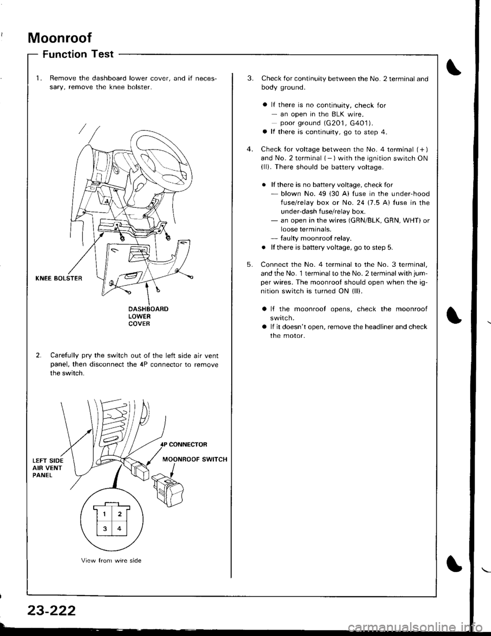
1.Remove the dashboard lower cover. and if neces-
sary, remove the knee bolster.
3.Check for continuity between the No. 2 terminal and
body ground.
a lf there is no continuity, check for- an open in the BLK wire.poor ground (G2O1, G4O1).a lf there is continuity, go to step 4.
Check tor voltage between the No. 4 terminal (+ )and No. 2 terminal { - ) with the ignition switch ON(ll). There should be battery voltage.
. lf there is no battery voltage, checkfor- blown No. 49 (30 A) fuse in the under-hood
fuse/relay box or No. 24 17.5 Al fuse in the
under-dash fuse/relay box.- an open in the wires (GRN/BLK, cRN, WHT) or
loose terminals.- faulty moonroof relay.
. lf there is battery voltage, go to step 5.
Connect the No. 4 terminal to the No. 3 terminal,
and the No. 1 terminalto the No. 2 terminal with jum-
per wires. The moonrool should open when the ig-
nition switch is turned ON (ll).
4.
5.
KNEE BOLSTER
LOWERCOVEB
2. Carefully pry the switch out of the left side air ventpanel, then disconnect the 4P connector to remove
the switch.
lf the moonrool opens, check the moonroof
swttcn.
lf it doesn't open, remove the headliner and check
the motor.
CONNECTOR
MOONROOF SWITCH
. F-_1 ,
11 2l
rt�1
13 0l
View from wire side
Page 1282 of 1681
I
Circuit Diagram
UNDER,DASNFUSE/RELAYBOX
YEL
-+-----t
I Zu',x I.I--
POWER MIRROR SWITCH
)
UNDER.HOOD FUSE/FELAY BOX
LEFT -
l_L______ ___l.l
/t\-------- --lt\
YEURED.
( ):Hatchback
23-225
Page 1284 of 1681

)
Function Test
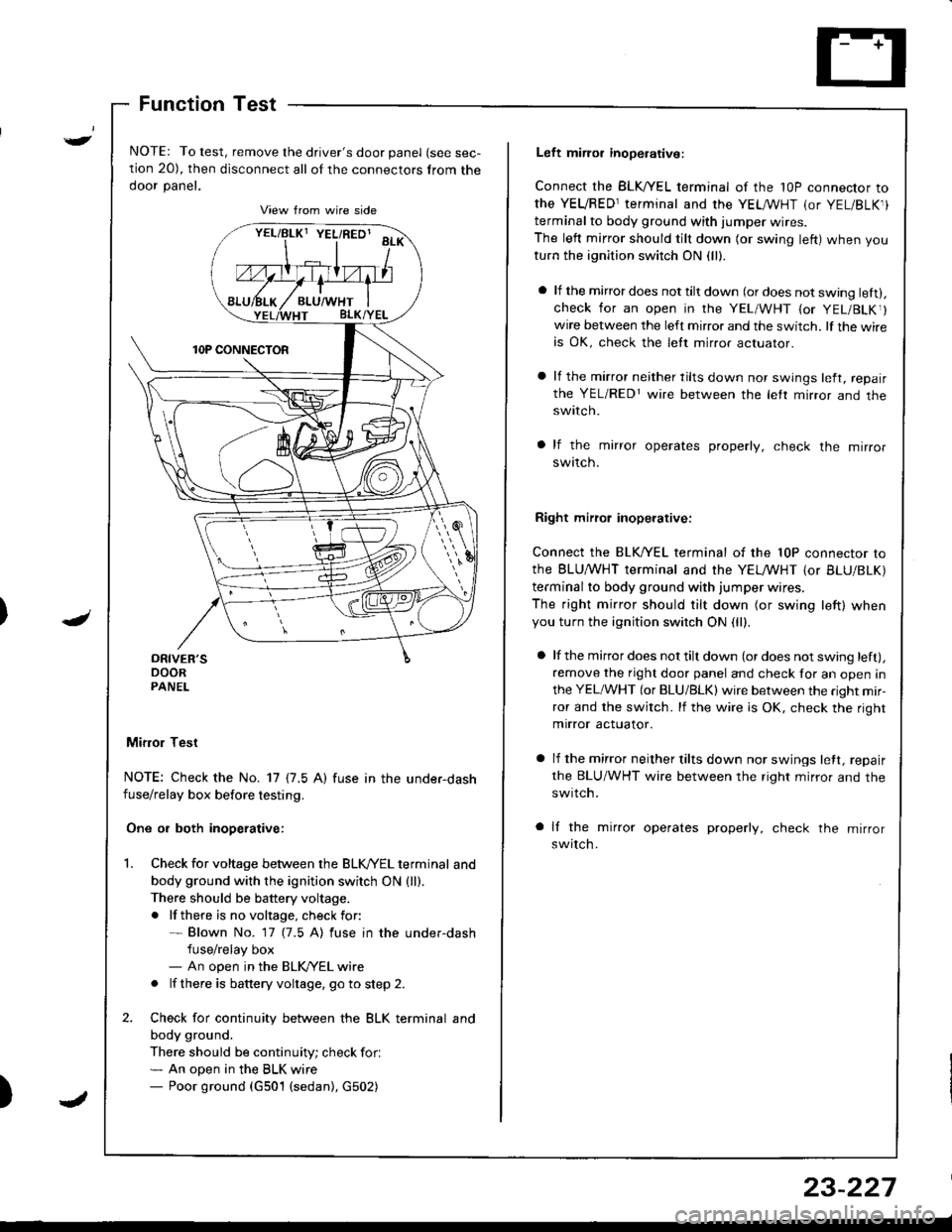
NOTE: To test, remove the driver's door panel (see sec-
tion 20), then disconnect all of the connectors from the
ooor panet.
Mifior Test
NOTE: Check the No. 17 {7.5 A) fuse in the under-dashfuse/relay box before testing.
One or both inoperative:
Check for voltage between the BLK//EL terminal and
body ground with the ignition switch ON {ll).There should be battery voltage.
. lf there is no voltage, check for:* Blown No. 17 (7.5 A) fuse in the under-dash
fuse/relay box- An open in the BLK/YEL wire
. lf there is battery voltage, go to step 2.
Check for continuity between the BLK terminal and
body ground.
There should be continuity; check for.* An open in the BLK wire- Poor ground (G501 (sedan), G502)
vrllBtxt YEL/RED' aa*\
Left miror inoperative:
Connect the BLK,^/EL terminal of the 1OP connector to
the YEVRED1terminal and the YEL /VHT (or YEL/BLK1)
terminal to body ground with iumper wires.
The left mirror should tilt down (or swing left) when you
turn the ignition switch ON (ll).
a lf the mirror does not tilt down (or does not swing lett).check for an open in the YEL/WHT {or YEL/BLKr}wire between the left mirror and the switch. lf the wireis OK, check the lett mirror actuaror.
a lf the mirror neither tilts down nor swings left, repair
the YEL/REDr wire between the letr mirror and theswtlcn.
a lf the mirror operates properly, check the mirror
swttcn.
Right mirrol inoperative:
Connect the BLK/YEL terminal of the 10P connector to
the BLU,^/VHT terminal and the YELMHT {or BLU/BLK)
terminal to body ground with jumper wires.
The right mirror should tilt down (or swing left) whenyou turn the ignition switch ON (ll).
a lf the mirror does not tilt down (or does not swing left),
remove the right door panel and check for an open in
the YEL/WHT (or BLU/BLK) wire between the right mir-
ror and the switch. lf the wire is OK, check the right
mirror actuator.
a lf the mirror neither tilts down nor swings lett, repair
the BLU/WHT wire between the right mirror and the
swrtch.
a lf the mirror operates properly, check the mirror
switch.
23-227
Page 1285 of 1681
Power Windows
POWER WINDOWMASTER SWITCH(Has built-in control unitiInput Test, page 23-234, 236Iesr, page 23-23'1 ,238Replacement, page 23'239
Component Location Index
UNDER.DASHFUSE/RELAY BOX
DRIVER'STest, page 23-240
LEFT REAR WINDOW MOTOR isedan)Test, page 23 240
POWER WINDOW RELAYTest, page 23-69
LEFT REAR WINDOW SWITCH {Sedan)Test, page 23 238Replacement, page 23 239
FRONT PASSENGER'S WINDOW SWITCHTest, page 23 238Replacement, page 23 239
FRONT PASSENGER'S WINDOW MOTOFTest, page 23-240
RIGHT REAR WINDOW SWITCH (Sedanl
Test, page 23 238Replacement, page 23-239
RIGHT REAR WINOOWMOTOR lsedanlTest, page 23-240
a rrrr'---rnnrn Tl---t----, .----r- L l
(
\
23-230