Page 715 of 1681

\
Front Toe Inspection/AdjustmentRear Toe Inspection/Adjustment
NOTE: Use commercially-available computerized four
whesl alignment equipment to measure wheel align-
ment (caster, camber, toe. and turning angle). Follow
the equipment manufacturer's instructions.
1.
2.
Check the tire pressure.
C€nter steering wheel spokes.
Check the toe with the wh€els pointed straight
ahead.
Front to6: 0 i 2 mm (0 t 1/16 in)
- lf adjustment is required. go on to step 4.
- lf no adjustment is required, remove alignment
equrpm€nr,
Loosen the ti€-rod locknuts and turn both tie-rods in
the same direction until the front wheels are in
straight ahead position.
Turn both tie-rods equally until the toe reading on
the turning radius gauge is correct.
After sdjusting, tighten the tie-rod locknuts.
NOT€: Reposition the tie-rod boot if it is twisted or
displaced.
TIE-ROD LOCKNUT14 x 1.5 mm
6.
a
NOTE: Use commercially-available computerized four
wheel alignment equipment to measure wheel align-
ment (caster, camber, toe, and turning angle), Follow
the equiDment manufacturer's instructions.
1. Release parking brake.
NOTE:
. Measure difference in toe measurements with
the wheels pointed straight ahead.
. lf the parking brake is engaged. you may get an
incorrect reading.
Rear toe-in: 2 11 mm l1l16 i 1/15 in)
- lf adjustment is required, go to step 2.
- lf no adjustment is required, remove alignment
equipment.
Before adjustment, note the locations of adjusting
bolts on the right and left compensator arms.
Loosen the adjusting bolts and slide the compen-
sator arm in or out as shown, to adjust the toe.
Tighten the adjusting bolts.
ADJUSTING BOLT10 x 1.25 mm
COMPENSATOR ARM
. Example;
A{ter the rear toe inspection, the wheel is 2 mm(0.08 inl out of the soecification.- Move the arm so the adjusting bolt moves 2 mm(0.08 inl inward from the position recorded betore theadjustment.- The distance the adjusting bolt is moved should be
equal to the amount out-of-specification.
6a N.m 16.5 kgt m, 47 lbt.ft)
a4 N.m la.s kgI.m, 33 lbf.ft)
18-5
Page 1183 of 1681
1.
2.
Gauge Assembly
Removal
Remove the two screws from the instrument panel.
Remove the instrument panel.
NOTE: Remove the instrument panel carefully
without damaging the clips.
23-126
3.
5.
Tilt the steering wheel down with the tilt adjustment
lever.
Remove the three mounting screws, and spread a
protective cloth on the steering column.
PROTECTIVE CLOTH
Pry the gauge assembly out, and disconnect all con
nectors from it.
6:
GAUGE ASSEMBLY
Take out the gauge assembly as shown.
GAUGE ASSEMBLY
Page 1340 of 1681

Precautions/Procedures
Steering-related Precautions
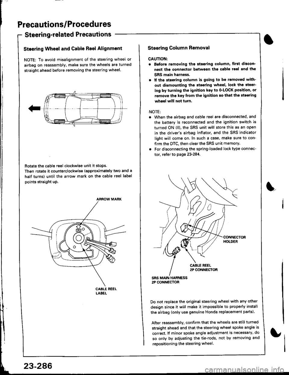
Steering Wheel and Gable Reel Alignment
NOTE: To avoid misalignment of the steering wheel or
airbag on reassembly. make sure the wheels are turned
straight ahead before removing the steering wheel.
Rotate the cable reel clockwise unit it stops.
Then rotate it counterclockwise (approximately two and a
half turns) until the arrow mark on the cable reel label
points straight up.
ARROW MARK
23-286
Steering Column Removal
CAUTION:
. Before romoving the steoring column, lirst di3con-
nect ths connector bctwoen tho csble rsal and the
SBS main harneEs.
. lf the steeting column is going to be rsmoved with-
out dismounting the steering wheel, lock the steer-
ing by iurning the ignition k6y to o'LOCK position' or
remove tho key lrom thc ignition ro that the steering
wheel will not turn.
NOTE:
When the airbag and cable reel are disconnected, and
the battery is reconnected and the ignition switch is
turned ON (ll), the SRS unit will store this as an open
in the driver's airbag inflator, and the SRS indicator
light will come on. In such a case, make sure to con-
firm the DTC, then clear the SRS unit memory.
For disconnecting the spring-loaded lock type connec-
tor, refer to page 23-284,
SRS MAIN HARNESS2P CONNECTOR
Do not replace the original steering wheel with any other
design since it will make it impossible to properly install
the airbag {only use genuine Honda replacement parts).
After reassembly. confirm that the wheels are still turned
straight ahead and that the steering wheel spoke angle is
correct, lf minor spoke angle adjustment is necessary, do
so only by adjusting the tie-rods, not by removing and
repositioning the steering wheel.
L
Page 1378 of 1681

Cable Reel
Replacement (cont'dl
CAUTION:
. Before installing the steering wheel, the lront
wheels should be aligned str8ight ahead.
. Be sure to install the harness wires so that they
are not pinched or interfering with other parts.
. After reassembly, confirm thal the wheels are
slill turned str8ight ahead and that the steering
wheel spoke angle is correst (road test). lf minol
spoke angle adjustment is necessary, do so only
by adiusting the tie-.ods, not by removing and
repositioning the steering wheel.
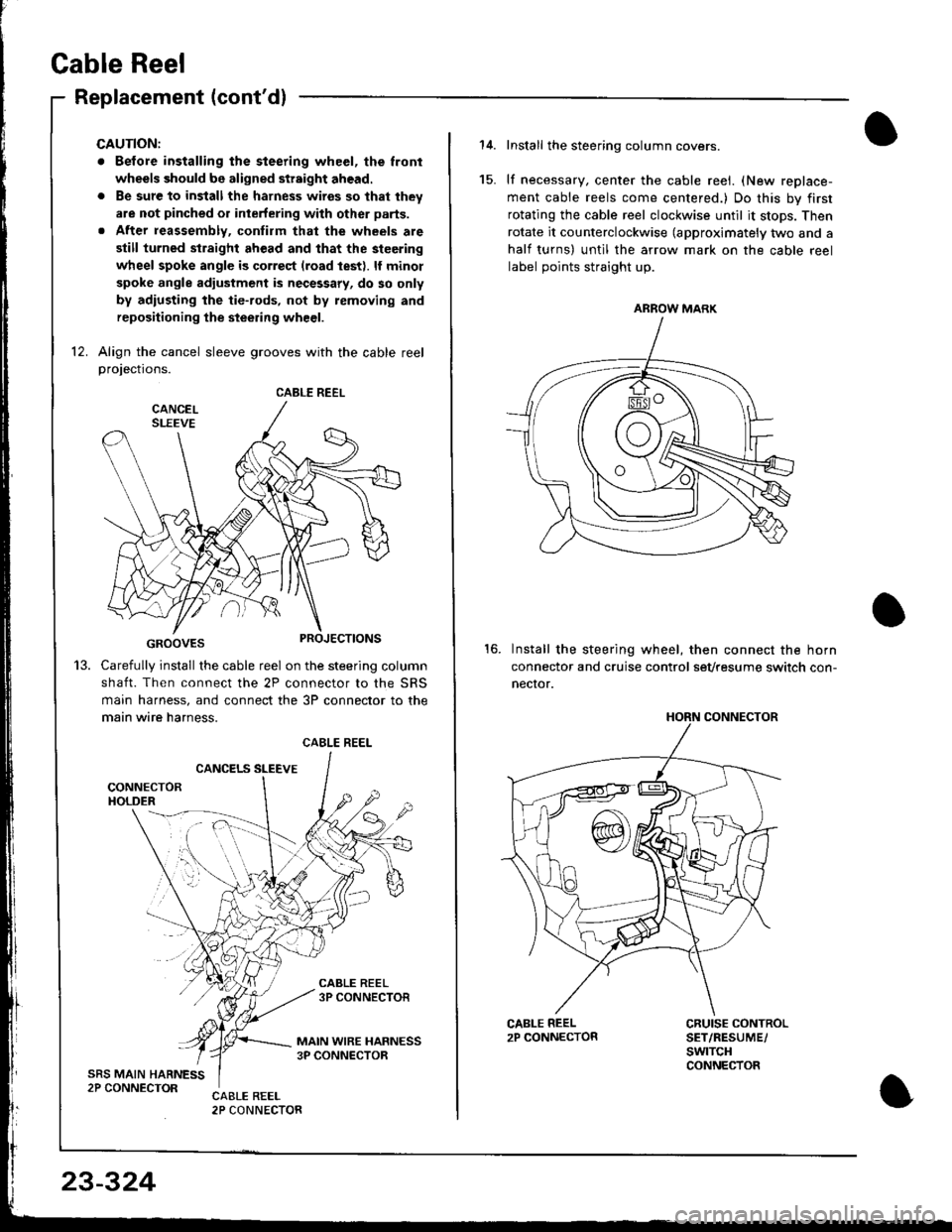
12. Align the cancel sleeve grooves with the cable reelprojections.
GROOVES
Carefully install the cable reel on the steering column
shaft. Then connect the 2P connector to the SRS
main harness, and connect the 3P connector to the
main wire harness.
CANCELS SLEEVE
CABLE REEL
13.
CABLE REEL
23-324
Install the steering column covers.
lf necessary, center the cable reei. (New replace-
ment cable reels come centered.) Do this by first
rotating the cable reel clockwise until it stops. Then
rotate it counterclockwise (approximately two and a
half turns) untll the arrow mark on the cable reel
label points straight up.
Install the steering wheel, then connect the horn
connector and cruise control sevtesume switch con-
necror.
15.
16.
CRUISE CONTROLSET/RESUME/swtTcHCONNECTOR
ARROW MARK
HORN CONNECTOR