1998 HONDA INTEGRA oil change
[x] Cancel search: oil changePage 384 of 1681

Shift Rod
- Removal
13-18
1. Remove the shift rod boots.
2. Remove the change piece attaching bolt and the
spring washer,
3. Remove the set screw. then remove the spring and
the steel ball.
4,
5.
Remove the shift rod, then remove the change
prece.
Remove the oil seal.
CHANGE
\
\
I
PIECE
SPRINGL.25.6 r(1.01 in)
STEEL B(D.5/16
OIL SEALReplace.
*q
SHIFTRODBOOTS
SPRING WASHER
SET screw
ATTACHING BOLT
Page 407 of 1681

I
t
\
Transmission
Reassembly
1. Install the new oil seal.
2. Set the change piece.
3. lnstall the shift rod.
4. Install the steel ball, the spring, and the set screw.
5. Install the change piece attaching bolt.
6. Install the shift rod boots.
8x1.0mm30 N.m (3.1 kgf.m,22tbfitl
SHIFT ROD
7. Installthe oil chamber plate.
7 .' L. 25.6 mfi BOI
@ ,zt tt.o'ti"t I
Y-",:'b>,",CI
6x1.0mm12 N.m {1.2 kgl.m,9 lbf.ft)
8. Install the differential assembly.
DIFFERENTIALASSEMBLY
Position the spring washer and the washer onto the
mainshaft bearing.
Install the mainshaft, the countershaft. and the shift
fork assemblies.
NOTE: Align the finger of the interlock with rhegroove in the shift fork shaft.
MAINSHAFT
SHIFT FORKS
(cont'd)
10.
13-41
Page 420 of 1681

Description
\J
t{
{
14-3
The automatic transmission is a combination of a 3-element torque converter and triple-shalt electronically controlled
automatic transmission which provides 4 speeds forward and 1 speed reverse. The entire unit is positioned in line with
the engrne.
Torque Converter, Gears, and Clutches
The torque converter consists of a pump, turbine, and stator, assembled in sigle unit. The torque converter is connected to
the engine crankshaft so they turn torether as a unit as the engine turns. Around the outside of the torque convener is a
ring gear which meshes with the starter pinion when the engine is being started. The entire torque converter assembly
serves as a flywheel while transmitting power to the transmission mainshaft.
The transmission has three parallel shafts; the mainshaft. the countershaft, and the sub shaft. The mainshaft is in-line with
the engine crankshaft.
The mainshaft includes the 1st, and 2ndl4th clutches,and gear for 3rd, 2nd, 4th, reverse, and 1st. (3rd gear is integral with
the mainshaft, while reverse gear is integral with the 4th gear.)
The countershaft includes the 3rd clutch and gears for 3rd,2nd, 4th, reverse, 1st, and parking. Reverse and 4th gears can
be loched to the countershaft at its center,providing 4th gear or reverse, depending on which way the selector is moved.
The sub-shaft includes the 1st-hold clutch and gears fo 1st and 4th.
The gears on the mainshaft are in constant mesh with those on the countersahft and sub-shaft.When certain combinations
of gears in the transmission are engaged by clutches. power in transmitted from the mainshaft to the countershaft via the
sub-shaft to orovude oil, lo'1. E, E. and E.
Electronic Control
The electronic control svstem consists of the Transmission Control Module (TCM), sensors, and four solenoid valves.
Shilting and lock-up are electronically controlled for comfortable driving under all conditions.
The TCM is located below the dashboard, behind the lelt side kick panel on the driver's side.
Hydraulic Control
The valve bodies include the main valve body, the secondary valve body, the regulator valve body, the serbvo body, and
the lock-up valve body, through the respective separator plates, They are bolted to the torque converter housing,
The main valve body contains the manual valve, the 1-2 shift valve, the 2-3 shitt valve, the Clutch Pressure Control
lCPC) valve, the 4th exhaust valve, the reliel valve, and the ATF pump gears.
The secondary valve body contains the 4-3 kick-down valve, the 3-2 kick-down valve, the 2-3 orifice control valve, the
3-4 shift valve, the orilice control valve, the modulator valve, and the servo control valve.
The regulator valve body contains the pressure regulator valve, the lock-up control valve, the torque converter check
valve, and the cooler check valve.
The servo body contains the servo valve, which is integrated with shift fork shaft, the throttle valve B, and the accumula-
tors.
The lock-up valve body contains the lock-up shift valve and the lock-up timing B valve, and is bolted to the regulator valve
ooqy.
Fluid from the regulator passes through the manual valve to the various control valves.
Shift Control Mechanism
Input to the TCM from various sensors located throughout the car determines which shift control solenoid valve should
be activated. Activating a shitt control solenoid valve changes modulator pressure, causing a shift valve to move. This
pressurizes a line to one ol the clutches, engaging that clutch and its corresponding gear.
Lock-uD Mechanism
In @ position, in 2nd, 3rd and 4th, and @ position in 3rd, pressurized fluid can be drained lrom the back oI the tor-
que converter through a fluid passage, causing the lock-up piston to be held against the torque converter cover. As this
takes place, the mainshaft rotates at the same speed as the engine crankshaft. Together with hydraulic control, the TCM
optimizes the timing of the lock-up mechanism.
The lock-up valves controlthe range of lock-up according to lock-up control solenoid valves A and B, and throttle valve B.
When lock-up control solenoid valves A and B activate, modulator pressure changes. Lock-up control solenoid valves
A and B are mounted on the torque converter housing, and are controlled by the TCM.
(cont'd)
Page 731 of 1681

lnstallation
CAUTION: Th€ vehiclo should bs on the ground b€fore any bolts or nuis connectod to rubber mounis or bushings aro
tightened.
NOTE:
. Wipe off thedirt,oil or gr€ase on the threads before tightening the fasteners.
. The right and left damper forks are not interchangeable. The left damper fork is ma.ked with "VL" while the righr
damoer fork is marked with "VR".
. The right and left upper arms are not interchangeable. The left upper arm is marked with "SRZ-L" while the right arm is
marked with "SRZ-R".
. Before tightening the upper and lower mounting nuts on the stabilizer link, adjust the location ot the link with the sus-
pension under vehicle load.
. When installing the radius arm washers, the "FR" mark faces the front ofthe car.
. After installing the suspension a rm, check the front wheel alignmentand adjust if necesssry (see page 18-4).
SELF-LOCKING NUT12 x 1.25 nn64 N.m {6,5 kg{.m, 47Replace.
STABILIZER BARAlign the stabilazer markwith end of stabilizer
BOLT
STABILIZER EUSHING
SELF.LOCKING NUTI x 1.25 mm22 N.m 12.2 kgt m, 16 lbf.ft)Replace.
FLANGE BOLT12 x 1.25 mm
FLANGE NUTI x 1.25 mm22 N.m {2.2 kgt m. 16 lbf.ft}
BADIUS ARM WASHER B{SMALL I.D.)
\64 N.m {6.5 kg{.m, 47 lbt.ft) .SELF.LOCKING NUT14 x 1.5 mm83 N.m {8.5 kgI.m, 61 lbl.ftlReplace.
RAOIUS ARM WASHER A{LARGE I.O.I
.@]
SILICONE GREASERUBBER BUSHING
FLANGE BOLTS14 x 1.5 mm89 N.m {9.1 kgf.m, 66 lbtft)
RS, LS Modebi
SELF.LOCKING NUT8 x 1.25 mm22 N.m (2.2 kg,f.m. 16lbtftl
SELF.LOCKING NUTI x I .25 mm22 N m {2.2 kgt'm, 15 lbf.ft)Replace.
14 x 1.5 mm89 N m {9.1 kgf m,66lblft)
SELF-LOC(ING NUTl0 x 1.25 mm29 N.m 13.0 kgf.m,22 lbtftlReplace.Hold the balljoint pin using ahex wrench, and tighten the self-locking nut.
FLANGE BOLT10 x 1.25 mm43 N.m {4.4 kgl.m, 32lbf.ft}
SELF-LOCKING NUT12 x 1.25 mm64 N.m {6.5 kgf.m, 47 lbtftlReplace.
SELF-LOCKING NUT 8 x 1.25 mm22 N.m {2.2 kgI m, 16lbf.ft)
STABILIZER END RUBBER BUSHINGSNote the directionof the bushinas.
Replace.Before tightening the self locking nuts, position the ball joint pinat the center of the range in which the pin can be moved with thesuspension under vehicle load.
MARK
SILICONE GREASE
1A-21
Page 781 of 1681

Wheel Speed and Modulator Control
OUTLETVALVE oN
OFF
INLETVALVE ON
OFF
MOTOR
ON
OFF
When the wheel speed drops sharply below the vehicle speed, the inlet valve closes to retain the caliper fluid pressure.
When the wheel speed drops further, the outlet valve opens momentarily to reduce the caliper fluid pressure. The pump
motor starts at this time.
As the wheel speed is restored, the inlet valve opens momentarily to increase the caliper fluid pressure.
Wheel Sensor
The four wheel sensors are the magnetic contactless type. As the gear pulser teeth rotate past the wheel sensor's magnetic
coil, AC current is generated. The AC frequency changes in accordance with the wheel speed. The ABS control unit detects
the wheel sensor signalfrequency and thereby detects the wheel speed.
rr LOW SPEED
5
GEAR PUTSER
19-29
Page 1024 of 1681

Description
Outline
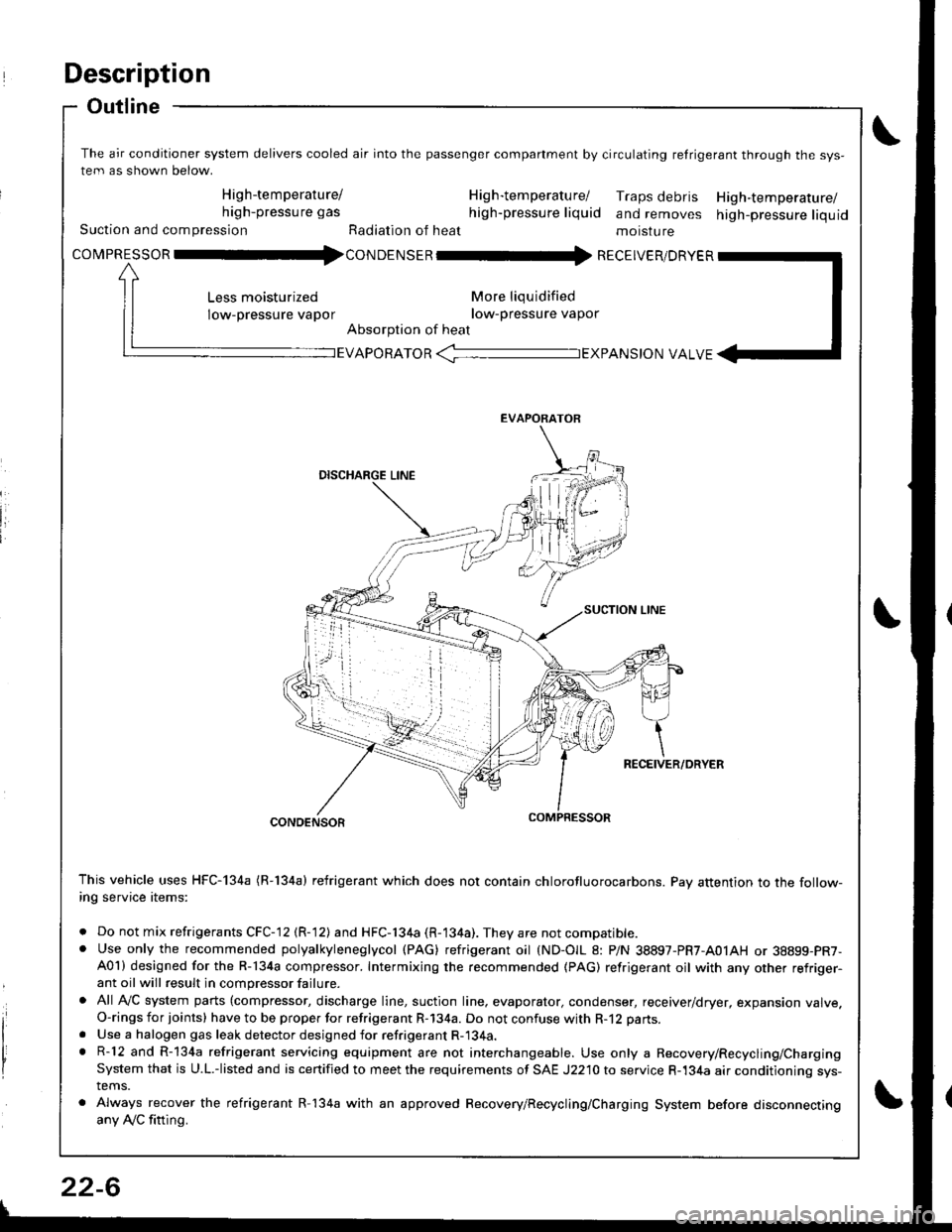
The air conditioner system delivers cooled air into the passenger companment by circulating retrigerant through the sys-
tem as shown below.
High-temperature/ H ig h-tem peratu rel Traps debris High-temperature/high-pressure gas high-pressure liquid and removes high-pressure liquidSuction and compression Radiation of heat moisture
covpnEsson -tl4con oetsen -rr{ REcEIvER/DRvER
More liqu idified
low-pressure vapor
Absorption of heat
Less moisturized
low-pressure vapor
EVAPORATOR -TEXPANS|ON VALVE
EVAPORATOR
CONDENSOR
This vehicle uses HFC-134a (R-134a) refrigerant which does not contain chlorofluorocarbons. Pay attention to the follow-ing service items:
. Do not mix refrigerants CFC-12 (R-12) and HFC-134a (R-134a). They are not compatible.. Use only the recommended polyalkyleneglycol (PAG) refrigerant oil (ND-OIL 8: P/N 38897-PR7-A01AH or 38899-PR7-A01) designed for the R-134a compressor. Intermixing the recommended (PAG) refrigerant oil with any other refriger-ant oil will result in compressor failure.
. All AVC system parts (compressor, discharge line, suction line. evaporator, condenser, receiver/dryer, expansion valve.O-rings for joints) have to be proper for refrigerant R-134a. Do not confuse with R-12 parts.
. Use a halogen gas leak detector designed for refrigerant R-134a.. R-12 and R-134a refrigerant servicing equipment are not interchangeable. Use only a Recovery/Recycling/ChargingSystem that is U.L.-listed and is certified to meet the requirements of SAE J2210 to service R-134a air conditioning sys-tems.
. Always recover the refrigerant R-134a with an approved Recovery/Recycling/Charging System before disconnectingany Ay'C fitting.
22-6
Page 1050 of 1681

Compressor
Clutch Inspection
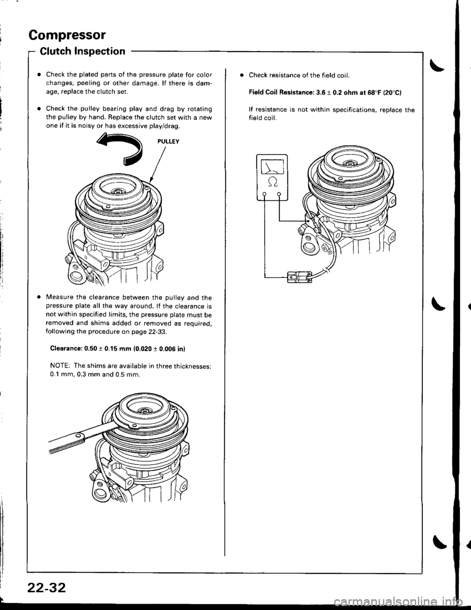
Check the plated parts of the pressure plate for color
changes, peeling or other damage. lf there is dam-
age, replace the clutch set.
Check the pulley bearing play and drag by rotating
the pulley by hand. Replace the clutch set with a new
one if it is noisy or has excessive play/drag.
Measure the clearance between the Dullev and thepressure plate all the way around. lf the clearance is
not within specified limits, the pressure plate must beremoved and shims added or removed as required,following the procedure on page 22-33.
Clearanca: 0.50 t 0.15 mm (0.020 r 0.006 in)
NOTE; The shims are available in three thicknesses:
0.1 mm, 0.3 mm and 0.5 mm.
22-32
Check resistance of the field coil.
Field Coil Resistance: 3.6 1 0.2 ohm at 68'F {20'C)
lf resistance is not within specifications, replace the
field coil.
Page 1500 of 1681

Gauges (cont'd)
- How the Circuit Works
When the ignition switch is in ON (ll) or START (lll),
battery voltage is supplied through fuse 25 to the
gauges in the gauge assembly.
Speedometer and Odometer
The odometer and speedometer drive circuits
receive pulses lrom the vehicle speed sensor
(VSS). The pulse rate increases as the car
accelerates. The frequency and duration of these
input pulses are measured and displayed by the
speedometer, odometer and tripmeter.
Tachometer ('98-'99 Models)
The tachometer drive circuit receives oulses from
the ignition control module (lCM) in the distributor
assembly. The solid-state tachometer then displays
these pulses as engine speed. For each 200 pulses
per minute from the ignition control module (lCM),
the tachometer displays 100 RPM.
Tachometer ('00 Model)
The tachometer drive circuit receives pulses f rom
the PCM or ECM. The solid-state tachometer then
displays these pulses as engine speed. For each
200 oulses oer minute trom the PCM or ECM the
tachometer displays 1 00 RPM.
Engine Coolant Temperature Gauge and Fuel
Gauge
The engine coolant temperature gauge has two
intersecting coils wound around a permanent
magnet rotor. Voltage applied to the coils, through
fuse 25, generates a magnetic field. The magnetic
field, controlled by the engine coolant temperature
gauge sending unit, causes the rotor to rotate and
the gauge needle to move. As the resistance in the
sending unit varies, current through the gauge coils
changes. The gauge needle moves toward the coil
with the strongest magnetic tield. The fuel gauge
works the same way.
The engine coolant temperature gauge sending
unit's resistance varies from about 137 ohms at low
engine temperature to between 30-46 ohms at high
temperature (radiator fan running).
The fuel gauge sending unit's resistance varies from
about 2-5 ohms at full, to about 110 ohms at empty.
When you turn the ignition switch to LOCK (0), the
gauge remains at the last reading until you turn lhe
ignition switch to ON (ll) or START (lll) again.
Refer to the Service Manual (Section 23, Electrical)
for specific tests or troubleshooting procedures.
81'2